 Gabor
GaborSchematics, design files and source code are available in the project's Github repository.
Meet Window Squatter and Desktop Crawler
The creatures come in two shapes, but their circuitry and programming is identical. The window squatter (which less generous souls have also called the beach chair) reaches up to catch the sunlight if your window has a thicker frame. The desktop crawler's natural habitat is a desk or shelf that gets a lot of direct sunlight. Here you can see them side-by-side at the pier on a recent sunny day.
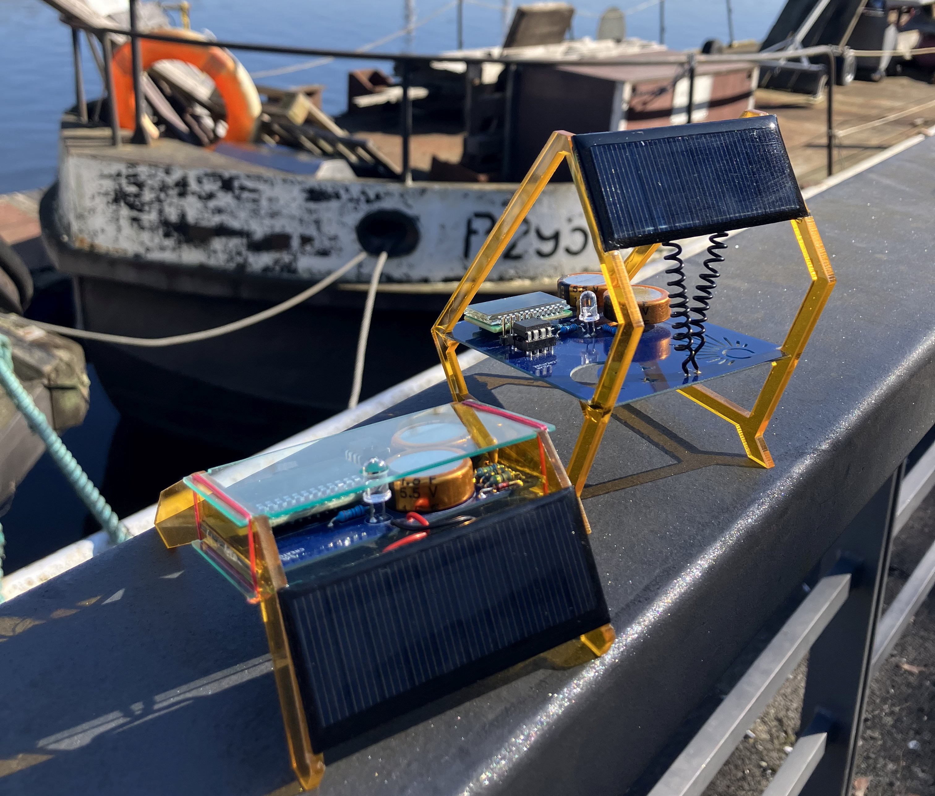
Built of circuit boards and acrylic
- The blue circuit board is the centerpiece of both creatures, because, hey, technology is beautiful! The PCB is particularly pronounced in the window squatter, where it goes wild with a sun & moon cutout.
- The frame is laser-cut from 3mm orange acrylic. The desktop crawler adds a top+bottom cover cut from 1mm blue-ish transparent acrylic.
- Both creatures are accessible for hacking and repair! The squatter exposes pins to measure voltage or reset the ATtiny. The chip itself can be removed from a socket so new firmware can be flashed onto it. The desktop crawler's covers are not glued in place but tied together with a fine fishing line. At one point the capacitors will die, but this way it's possible to go in, unsolder them and put in a new pair.
- The solar cell is a 30x70mm 5V or 6V piece.
- The LCD... Oh, the LCD from AliExpress with the weird segment-to-memory mapping! Read the build log for the juicy details.
Conway's Game of Life on a 7-segment LCD
Here's the Desktop Crawler playing an adapted version of Conway's Game of Life. The neighborhood rules create an infinite playing field that wraps around at the edges. Perhaps because of this, the simulation often reaches cycles that can be anywhere from 2 to 10 steps long. Up to a length of 4 the Creature detects loops and invokes the Chaos Monkey to randomly flip two positions. Usually this nudges the simulation towards a different stable state.
Euclidean rhythms
Here's a Creature playing a Euclidean rhytm for four voices. The rhythm's parameters are randomized every time a new animation starts.
Status report
In between animations, the Creatures give a quick update about themselves. How many days have they been alive? What's the current voltage of the supercaps? How long have they been awake today? How long they were awake yesterday, and the day before, and the one before that?
A beacon at night
Come night, the capacitors slowly drain. When the voltage drops below 3.3V, the LCD switches off and the Creature goes into ultra-low-power mode. Only the strong red LED blinks out a rhythm a few times a minute. The rhythm changes from night to night.
A tribute to classic solar circuits
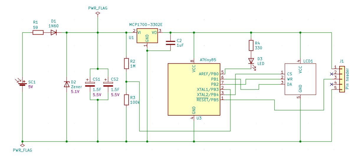
- The 1N60 Germanium diode, the 5V Zener and the small resistor are standard fare for solar projects with a supercap. The 1N60 has a low forward voltage and it makes sure the solar cell doesn't discharge the capacitor when it's dark. The Zener protects the capacitor from overvoltage.
- The rest of the circuit is behind an MCP1700-3302E LDO voltage regulator, so it never runs at more than 3.3V. That is part of how the creature saves power: the ATtiny's current draw is much less at lower voltages.
- R2+R1 divides the capacitor's voltage down so the ATtiny can measure it against its internal 1.1V reference voltage.
A program that spends (almost) all its life asleep
- The creatures spend most of their life sleeping. They have a faithful watchdog timer to wake them up regularly, so they can update the ongoing animation.
- There are different programs active depending on the voltage level. Above 4.1V it's all lively animations with Euclidean rhythms or an adaptation of Conway's Game of Life. Between 3.3V and 4.1 it's just a smiley face, and a quick status report about days alive, voltage level, hours awake, and hours awake in the past three days.
- Under 3.3V, till shutdown, it's a flashing light. Yes, the flashes are also guided by...
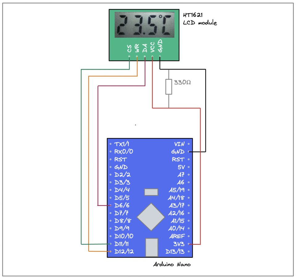
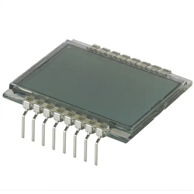 They are cheap, readily available - and a real pain to use. It's not just the sheer number of wires, though that's an issue as well. The problem with an LCD is that you cannot just send power to the right pins and hope for things to work out. You need to actively send alternatig signals to prevent irreversible chemical changes inside. People have done it before and written about it, and it makes for a really interesting read too:
 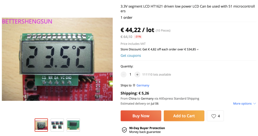 44€ might sound like a lot, but it's for a bag of 10, and I think when I placed my order it was more like 30€. Anyway, these postings come and go all the time and the price of the exact same product varies a lot, so it's worth searching around!
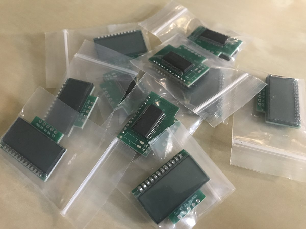

 strange.rand
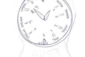
 Jan Waclawek
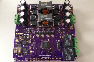
 Nathaniel VerLee
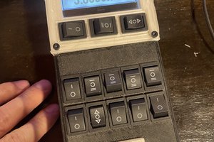
 John Duffy
Great project. Would you consider sharing the source code? I am particularly interested in the source for measuring the voltage. Thanks!