 Gabor
GaborOK, “reverse engineering” is a bit of an exaggeration here, but that was essentially the vibe when I first hooked up my mystery LCD component to an Arduino Nano.
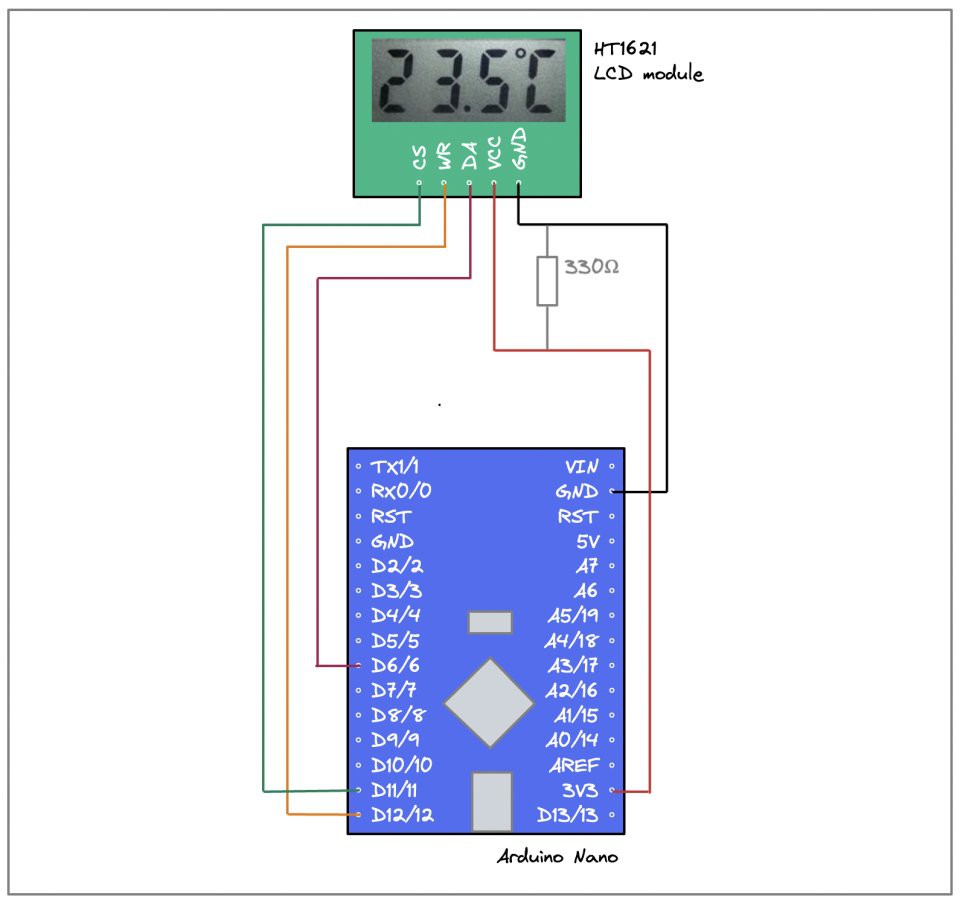
I’m not big on either Fritzing or Eagle, so I made a sketch of the wiring for you in Excalidraw :) The only thing that might need some explanation here is the 330Ω resistor between GND and the Nano board’s 3.3V output. I’m powering the board over USB, which is 5V. The 3.3V output comes from the on-board voltage regulator, but with no load I’m getting a higher voltage. The LCD component doesn’t like that: the off segments are turning black at a normal viewing angle. So I just did the easiest hack I could think of and added the resistor to create some load on the 3.3V VCC pin. This helps just enough, so I’m leaving it at this.
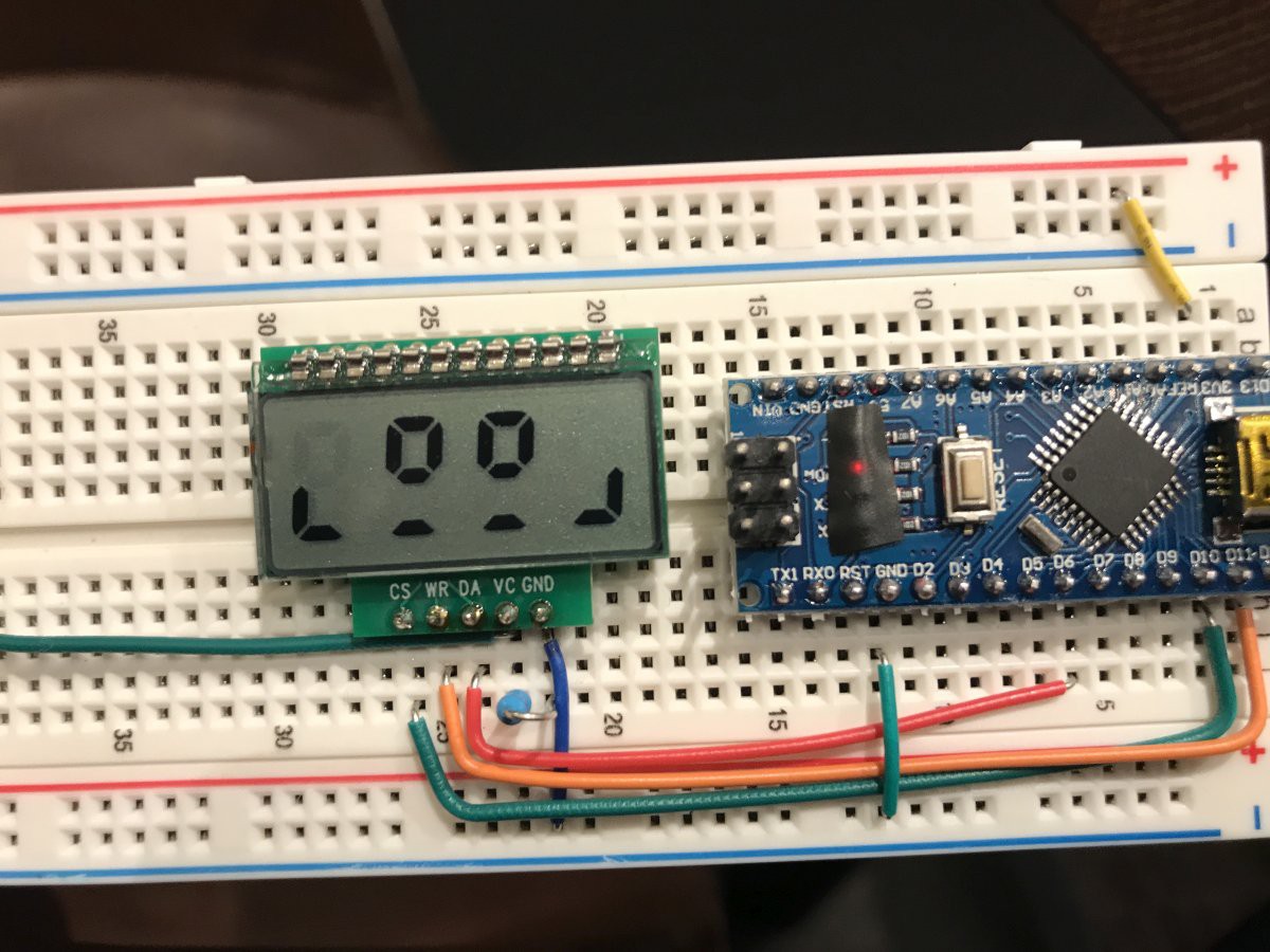
A bit of googling lead me to Valerio Nappi’s ht1621-7-seg library, so I went and wrote up a sketch that counted rapidly from 0 to 9999, took a deep breath, and uploaded it to the Nano. Here’s what happened:
That is actually... splendid news! The board can clearly talk to the LCD component, information is getting transmitted, and the display’s segments get turned on and off in response.
All that’s left is to figure out which bit in the library’s buffer corresponds to which segment on my display, because apparently this component is wired very differently from what Valerio was working with.
The magic in the library essentially boils down to this code snippet:
void HT1621::wrData(uint8_t data, uint8_t cnt)
{
 uint8_t i;
 for (i = 0; i < cnt; i++)
 {
   digitalWrite(PIN_WR, LOW);
   delayMicroseconds(4);
   digitalWrite(PIN_DATA, (data & 0x80) ? HIGH : LOW);
   digitalWrite(PIN_WR, HIGH);
   delayMicroseconds(4);
   data <<= 1;
 }
}
The loop transfers cnt number of bits from data, starting with the highest-order bit and moving right. This technique of controlling the levels on the communication pins straight from code is called bit-banging, and it’s a straightforward implementation of the wire protocol described in the HT1621 datasheet:
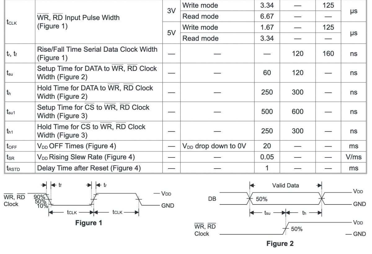
The 4 μs delay on the clock signal is at the lower end of what HT1621 accepts for writing, but hey, who wants to waste time saying nothing?
As I was experimenting I altered and reduced Valerio’s code in various ways:
- The original library has a 6-byte buffer, and always transmits all of it when updating the display. For some related display drivers that can control more segments this makes sense. But with my 32-segment LCD, only 4 bytes are ever used, so I reduced the buffer and don’t transmit the always-zero 16 bits during updates.
- The original class stores the index of the 3 pins it uses in memory, which makes sense in a general-purpose library. I switched to defines for this, eliminating another 3 bytes from my program’s memory footprint. This matters in the ATTiny85, where I only have 128 bytes! I’ll want to use them for cool animations and other funky behavior in the creature.
- I removed all functionality related to encoding digits and characters and moved that to a separate class. I consider that a different, higher layer; my HT1621 class only deals with controlling the display’s segments based on the bit values in a 4-byte buffer.
- I rewrote the command codes in binary notation, as that mirrors the specification in the datasheet more transparently than hex values. And I totally kept the Chinese comments, which must date back to anxzhu’s original library that Valerio forked :)
#define BIAS    0b01010010 // 1/3 duty 4 commons
#define SYSDIS  0b00000000 // 关振系统荡器和LCD偏压发生器 ~ disable sys oscillator and LCD bias
#define SYSEN   0b00000010 // 打开系统振荡器 ~ enable system oscillator
#define LCDOFF  0b00000100 // 关LCD偏压 ~ disable LCD bias generator
#define LCDON   0b00000110 // 打开LCD偏压 ~ enable LCD bias generator
#define XTAL    0b00101000 // 外部接时钟 ~ external quartz crystal
#define RC256   0b00110000 // 内部时钟 ~ internal RC oscillator
#define WDTDIS1 0b00001010 // 禁止看门狗 ~ disable watchdog timer
Now that we've come this far, let me present to you the result of my hard labor: the mystery LCD component's segment <-> bit mapping!
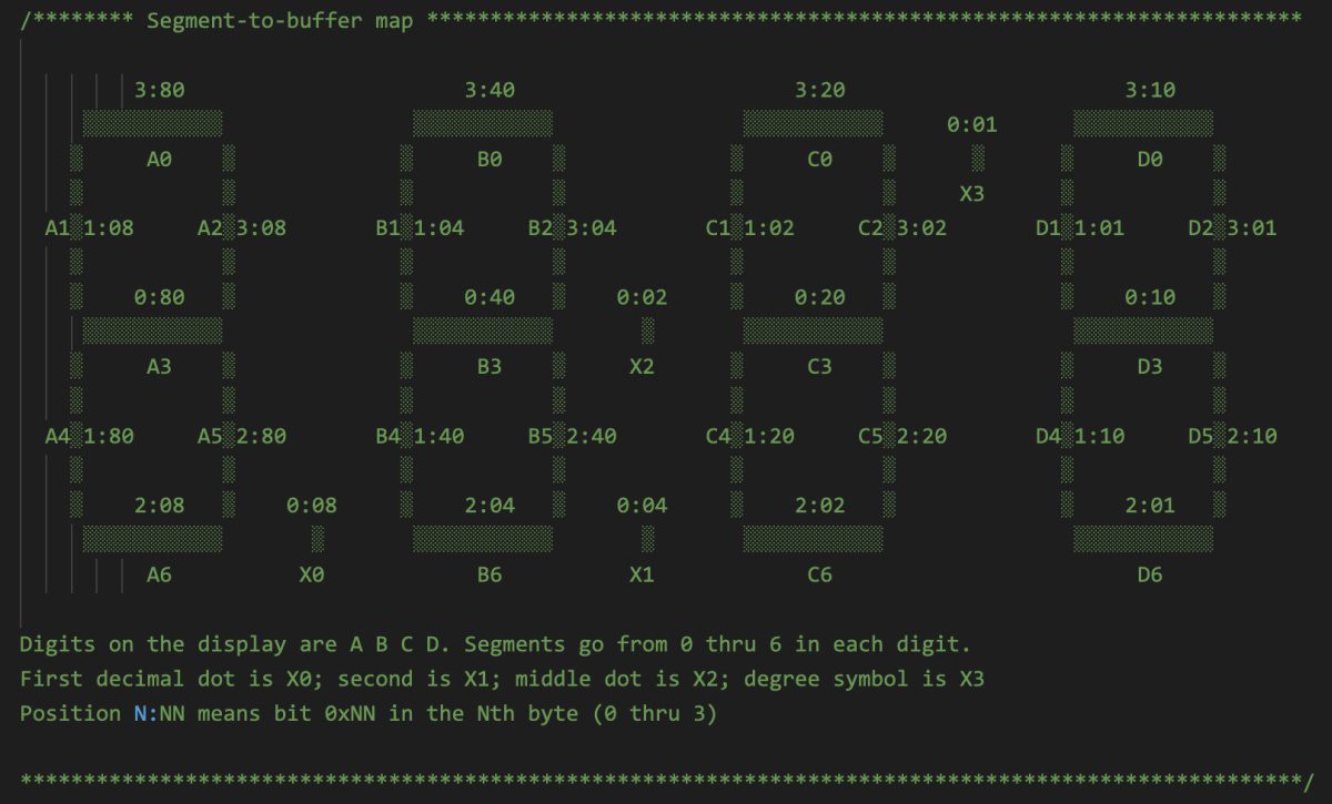
You can find this in code/src/HT1621.h on Github.
And this, of course, also means it's time to start being silly. Here’s a smiley frog face on a 7-segment display:
Links:
- HT1621 datasheet [archived]
- HT162x Application Guidelines [archived]
- Valerio Nappi’s ht1621-7-seg library
Discussions
Become a Hackaday.io Member
Create an account to leave a comment. Already have an account? Log In.
thanks, using your code i did it myself!
Are you sure? yes | no
Good afternoon
Great work!
Can you share the arduino IDE library code?
Are you sure? yes | no