Mortimer
Hello everyone, today I present you a solution/workaround to a well known and documented problem with all Cintiq Companion 2 models. The dreaded black-screen and or the no boot problem. I could identify some of the reason and it is a design flaw, as acknowledged by Wacom itself.
The Companion 2 utilizes a video controller chip to switch between the Intel Iris eDP (embedded Displayport) input to the internal display and the external HDMI input, which allows the device to be used as an external Cintiq graphics tablet. This chip is a 521 pin BGA Package called Athena STDP9320. Due to the design flaw this chip will die and will always die, even when replaced. I have tested this myself. The exact reason for the death is unknown but it is not heat, as I have even cooled it to test that.
Today we will remove the Athena chip and use thin wiring to connect the eDP output from the IGP (Integrated Graphics Processor) to the internal screen directly. We will also need to provide some voltages for the screen to turn on and be recognized. Please note that the Companion will no longer be usable as an external screen without external controllers, that would need to be wired/soldered in.
Symptoms:
-Black screen but Windows still runs in the background.
-When turned on the fans start spinning but stop after a short time, Windows did not boot up.
- The Athena STDP9320 gets very hot when attempting to boot the system. When the chip gets very hot there may also be coil whine.
-Before failure the screen may show black bars flickering for short moments.
-If Windows still boots and the internal screen is not recognized at all
Requirements:
-Cintiq Companion 2 1310, any variant
-Hot air SMD rework station with small tip soldering iron (2mm)
-Precision Tweezers ~.3mm tip
-Multimeter with precision probe
-Preheater to help remove the chip (Recommended)
-Good magnifying glass or digital microscope and bright light.
-Thin .2 or .3mm copper wire. (I suggest isolated wire.)
-Soldering flux
-Advanced skill soldering micro electronics
Please set up your work area.
Step 1.
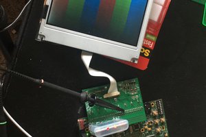
Remove the main PCB from the device and also remove all removable components. Place the PCB on the preheater.
Step 2.
See the image "Footprint clean" for reference
Place aluminum foil on the PCB an make a cutout at the Athenas position to protect surrounding components. Preheat the PCB to around 100~150C. Use hot air at 250 to 270C to liquefy the solder. Once you can move the chip, remove it with tweezers or the tool of you choosing. Then clean up the footprint to remove any unneeded solder left behind.
Step 3.
See the image "Pinout_Highlights" and "Connections".
Now comes the fun part. You will need to connect 12 wires of varying length. See the STDP9320 Pinout image and look at the marked contacts. They are almost all on the left hand side. Look at the Excel table to see which contacts will need to be connected. Signal in is the output coming from the IGP, out goes to the screen. The voltage pins are used to enable the display and to allow the IGP to detect the screen. LPM_DPTX_HPD comes directly from the screen so you will only measure this if you connect the screen and also connect PBIAS and PPWR first.
Step 4.
See the image "Measure-Here".
Once you have connected all of the pins you need to check if all connections are good. To do this measure between the orange and blue marked resistors. Orange comes from the IGP and blue goes to the screen. Make sure to only get continuity once. If you get continuity between one orange and blue for each wire, then all is good. Make sure there are no unwanted connections, because the signal pins are only rated for 1.2v. When everything is connected like this try plugging in the screen and turn the system on. If you have made no mistake, then it should work. Even backlight control should function.
Troubleshooting:
See the image "eDP_Pinout".
If you get nothing you will first need to...
Read more »
 davedarko
 Wenting Zhang
 Kumar, Abhishek