 Michael Perrone
Nanoparticle Synthesis
Thermionic devices are one
Surfactants Used:
- Polysorbate 20
- Polysorbate 80
- Glycerol Monostearate
- Triton X-100
- Dodecanol
- Dodecanethiol
- Lauric Acid
- Diaminododecane
- Dodecylamine
- Brij-L4
Solubility test in 50 mL water
- 0.0161g Dissolved easily
- 0.0192g Dissolved with heat
- 0.0180g Some dissolved, cloudy
- 0.0231g Dissolved with heat
- 0.0133g Did not dissolve easily
- 0.0163g Did not dissolve easily
- 0.0239g Did not dissolve easily
- 0.0183g Did not dissolve easily
- 0.0134g Some dissolved, cloudy
- 0.0155g Some dissolved, cloudy
Silver Nanoparticle Synthesis:
Surfactants F and I (Dodecanethiol and Dodecylamine) were eliminated from the proceedings due to air sensitivity.
Surfactant |
Name |
Molar Mass |
Concentration |
Amount Added to 50 mL |
A |
Polysorbate 20 |
1226 (g/mol) |
.0005 M |
30.65 mg |
B |
Polysorbate 80 |
1310 (g/mol) |
.0005 M |
32.75 mg |
C |
Glycerol Monostearate |
358.563 (g/mol) |
.0005 M |
8.96 mg |
D |
Triton X-100 |
647 (g/mol) |
.0005 M |
16.18 mg |
E |
Dodecanol |
186.34 (g/mol) |
.001 M |
9.32 mg |
F |
Dodecanethiol |
N/A |
N/A |
N/A |
G |
Lauric Acid |
202.3998 (g/mol) |
.001 M |
10.12 mg |
H |
Diaminododecane |
200.37 (g/mol) |
.001 M |
10.02 mg |
I |
Dodecylamine |
N/A |
N/A |
N/A |
J |
Brij-L4 |
362.5 (g/mol) |
.0005 M |
9.06 mg |
Table 1: Names and amounts of surfactants used
For the synthesis of silver nanoparticles, 100 mL of .00025 M silver nitrate solution was prepared. This is enough for each of the different surfactant solutions, as 12.5 mL is used for each of the 8 options.
For each individual surfactant solution, 50 mL of a .0005 M solution (apart from E, G, and H, which were .001 M) of the surfactant was made with DI water (see table 1 for surfactant quantities). This solution was heated to 70 C to assist in dissolving the surfactant, stirring constantly. Once heated, the solution is put in an ice bath and chilled to 10 C. Upon reaching this temperature, 1.89 mg of sodium borohydride is added to make a solution with .001 M surfactant and .001 M sodium borohydride.
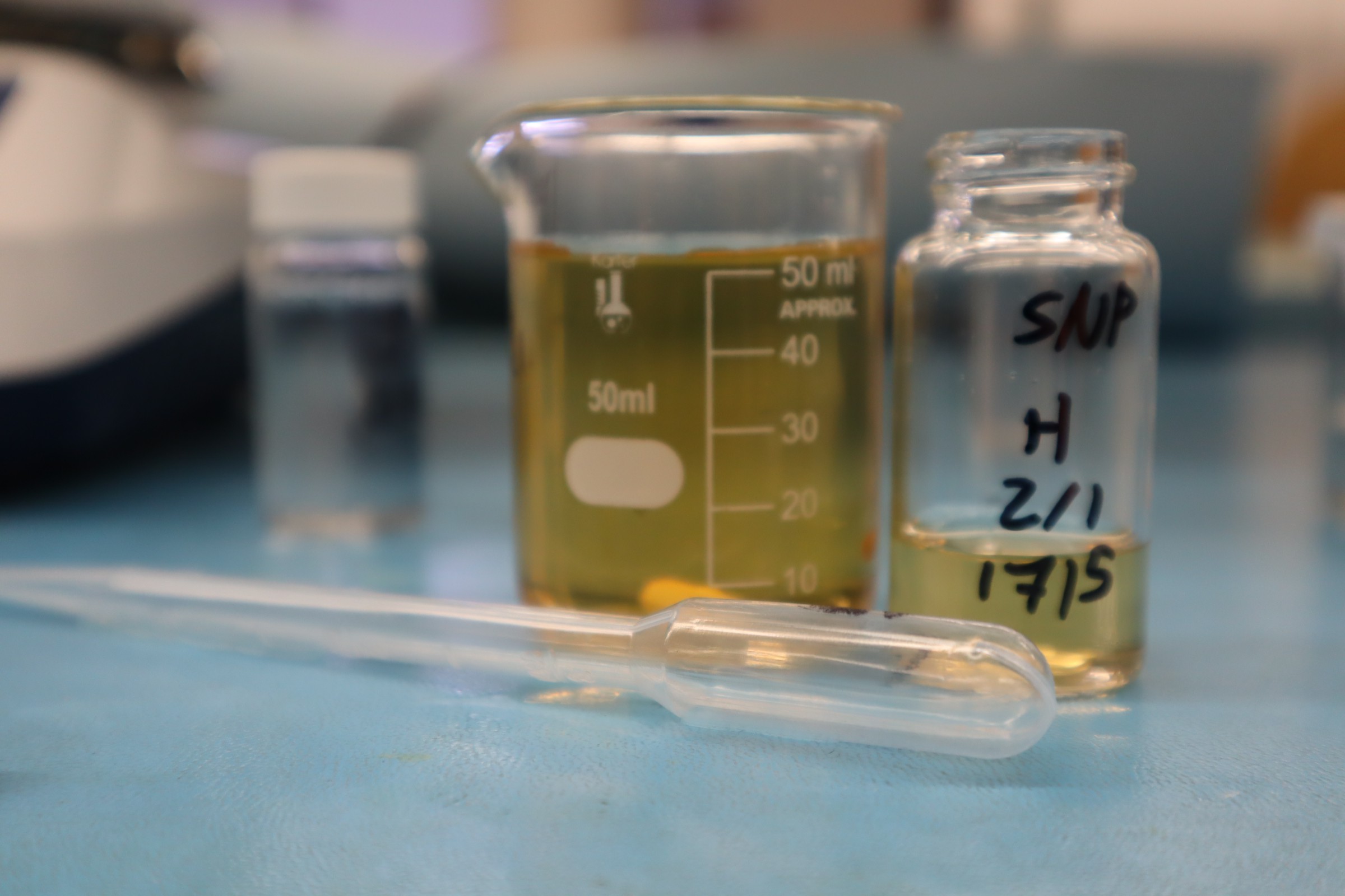
figure 2: Silver nanoparticles showing the gold/yellow color
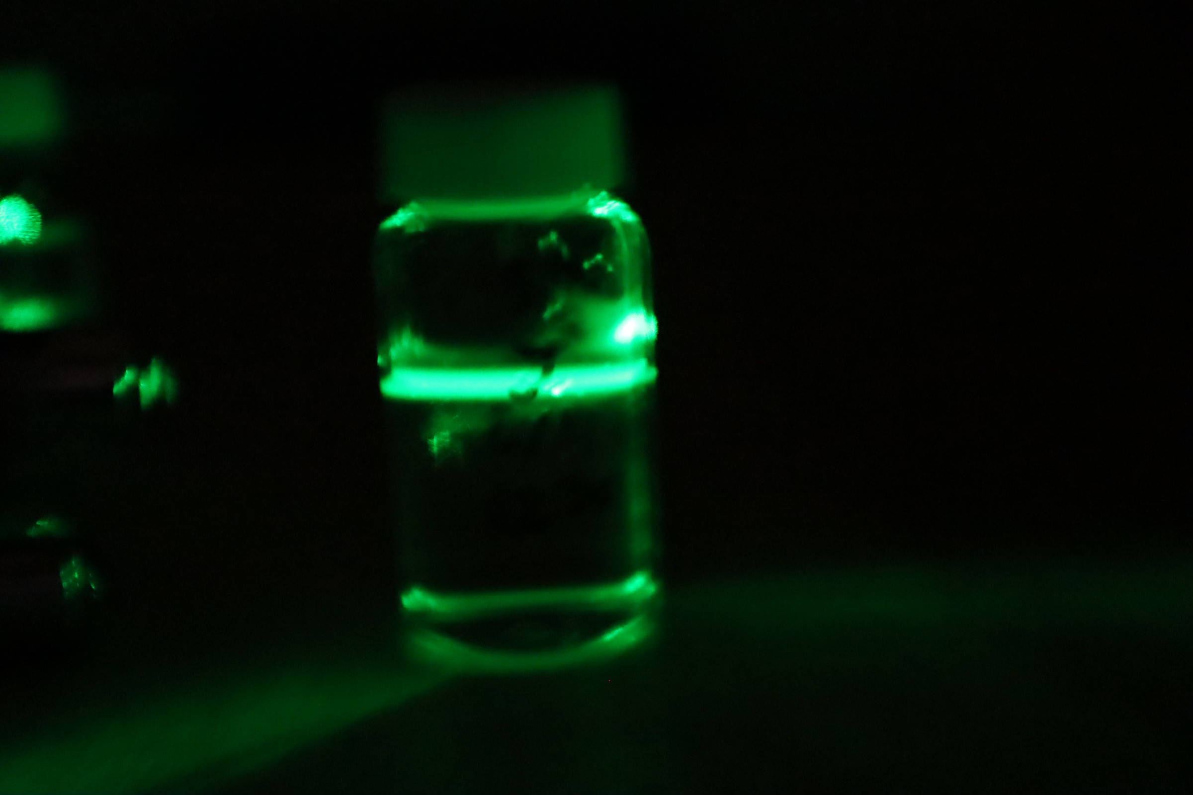
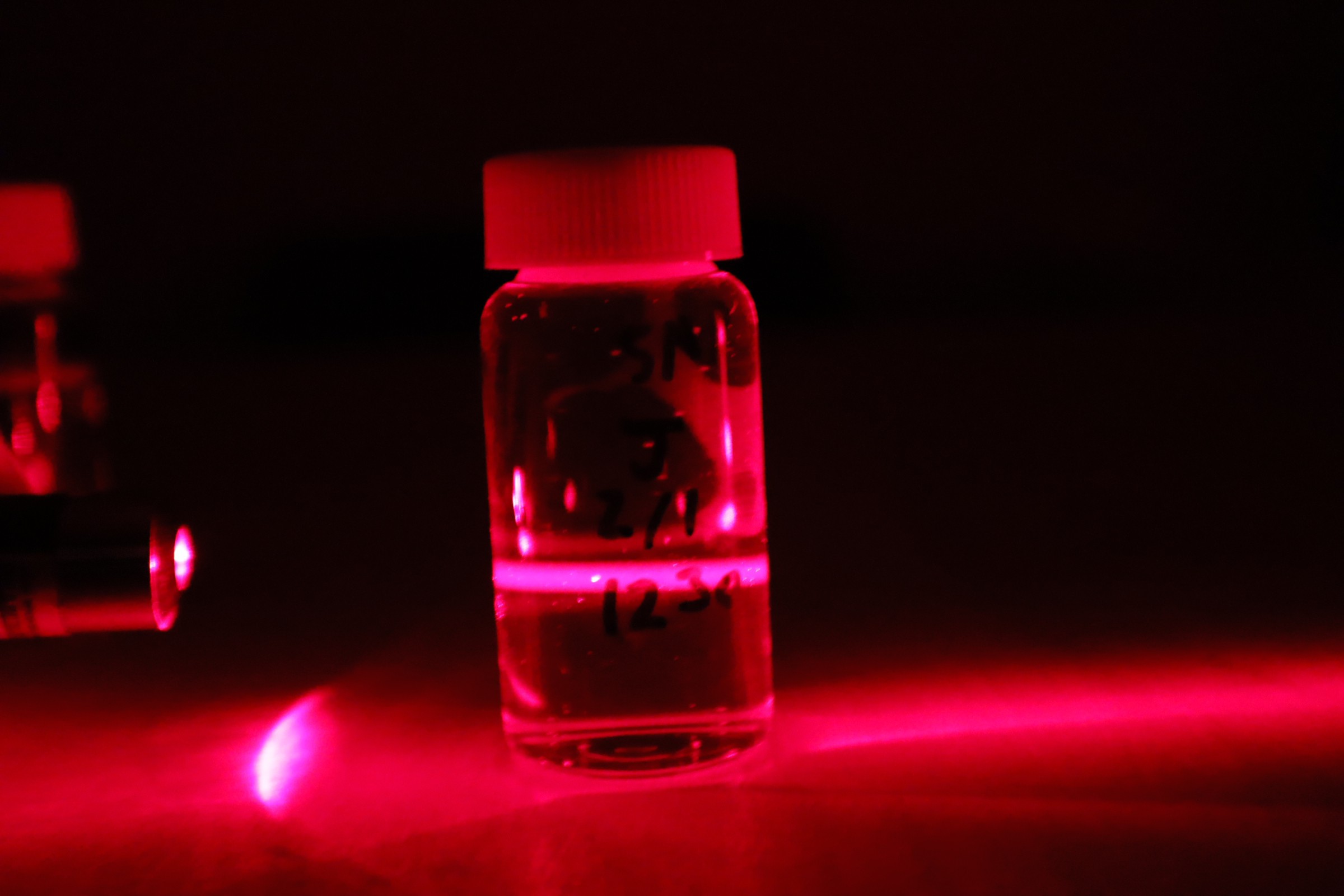
Immediately after the sodium borohydride is added, 12.5 mL of the .00025 M silver nitrate solution is added dropwise at a rate of approx. 1 drop per second, stirring constantly. As the silver nitrate solution is added, the solution turns to a yellow/amber color. The resulting solution is removed from the ice bath and divided into vials. Red, green, and blue lasers were shined through the vials to see the effects of the nanoparticles on the light.

Bismuth Nanoparticle Synthesis
To produce bismuth nanoparticles, we first need to make the compounds used in the synthesis. We first obtained Bi powder using Pepto-Bismol. The Pepto-Bismol was evaporated in an oven set to 140 C for approximately 6-10 hours, until all the liquid is gone. Once all the liquid evaporated, the resulting solid was baked in a kiln at 600 C for 2 hours, loosely covered with a lid to prevent evaporation of the bismuth oxide.
From there, we mixed 37% hydrochloric acid and potassium nitrate, both added in equal weight. To that we added the Bi powder in excess and mixed on hot plate set to 100 C. The container was capped loosely to discourage evaporation while not being put under pressure, in a “poor man’s aqua regia” setup. This is not an optimal mixture, but worked for our purposes.
To the resulting bismuth nitrate/bismuth chloride, we added sodium hydroxide until the mixture was basic. Once done, the bismuth precipitated out as bismuth oxychloride. This was rinsed over a filter and dried. It was then weighed and crushed into a fine powder. Formic acid was added to the powder to create bismuth formate.
The bismuth formate was then rinsed with DI water to remove the chloride ions. Once rinsed, it was dissolved in DI water at a concentration of .01 M. This solution was used in both the first and second iteration of the bismuth nanoparticle synthesis.
Bismuth Nanoparticles Attempt 1:
With our first attempt at producing bismuth nanoparticles, we noted a possible need to substitute acetic acid for the sodium borohydride. The .01 M solution of Bismuth formate was cloudy, so we added HCl dropwise until it cleared up. This was approximately 10 mL of HCl added to the 250 mL of the .01 M solution.
During this attempt, we began by using the same ratios and procedures as we did with silver. We first made an .00025 M bismuth formate solution by diluting the cleared .01 M solution. We then followed the same procedure as with the silver nanoparticles, substituting the bismuth formate solution for the silver nitrate.
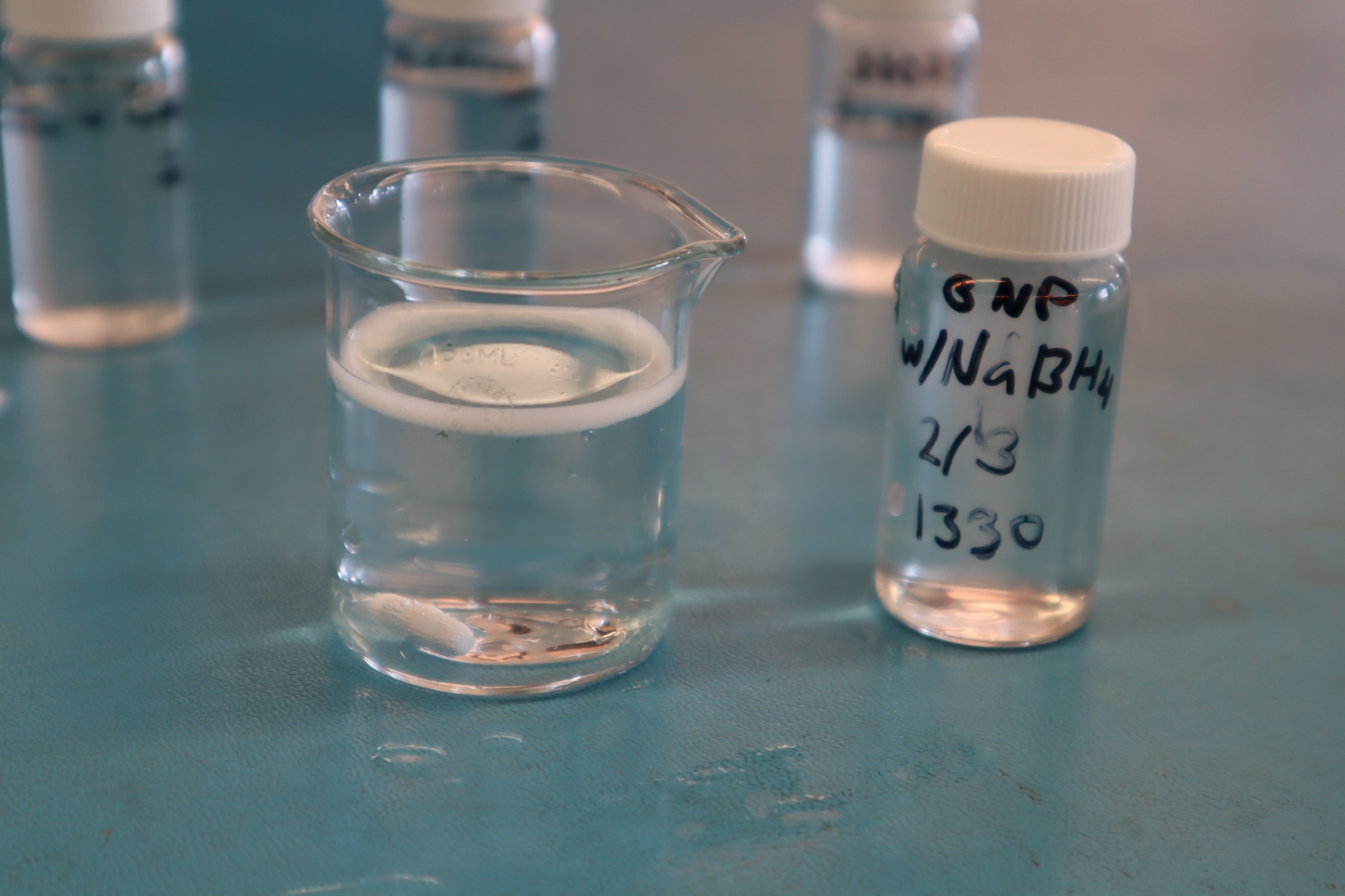
Figure 4: Foaming of the bismuth formate after attempting to use sodium borohydride to make nanoparticles
Starting with surfactant A, the polysorbate 20, we followed
the same amounts used with the silver as dictated in table 1. The
solution was heated to 70 C and stirred until the surfactant
dissolved. It was then chilled to 10 C and the sodium borohydride
added. 12.5 mL of the bismuth formate was added dropwise, stirring
constantly.
Unfortunately, the bismuth formate bubbled and broke down immediately instead of forming nanoparticles, as seen in figure 4.
Bismuth Nanoparticles Attempt 2:
On our second attempt, we tried using ascorbic acid instead of sodium borohydride. We again started with Polysorbate 20, though we increased doubled the concentration to .001 M. The same heating and chilling procedures were followed, before adding .0088 g of the ascorbic acid to our 50 mL solution, making a concentration of .001 M.
The mixture did not color when doing this, so we heated it to attempt to react the components. At 70 C, the mixture was cloudy, while at 75 C the mixture cleared. It clouded again at 80 C, and cleared after being held at 80 C. With this the mixture continued to show no color, indicating no nanoparticles were formed.
Bismuth Nanoparticles Attempt 3:
We decided to substitute propylene glycol for DI water for the bismuth nanoparticles. We mixed up surfactant solutions in the propylene glycol with the molarity described in table 1. We then added bismuth formate, at a ratio of 2.5 mL of the .01 M mixture per 50 mL of the propylene glycol mixture.
It should be noted that the bismuth formate tends to settle out of solution, and that it needs to be remixed before using. We put the sealed vial inside an ultrasonic cleaner to break up the larger settled particles and shook the bottle immediately before pipetting the 2.5 mL into the propylene glycol in order to ensure a uniform concentration.
The resulting solution was put on a hot plate, and brought to 180 C, stirring constantly. As the solution heated, bismuth nanoparticles formed, indicated by a yellowing of the mixture. The process was repeated for each surfactant, and the resulting nanoparticle mixture was bottled and set aside for further experiments and longevity testing.
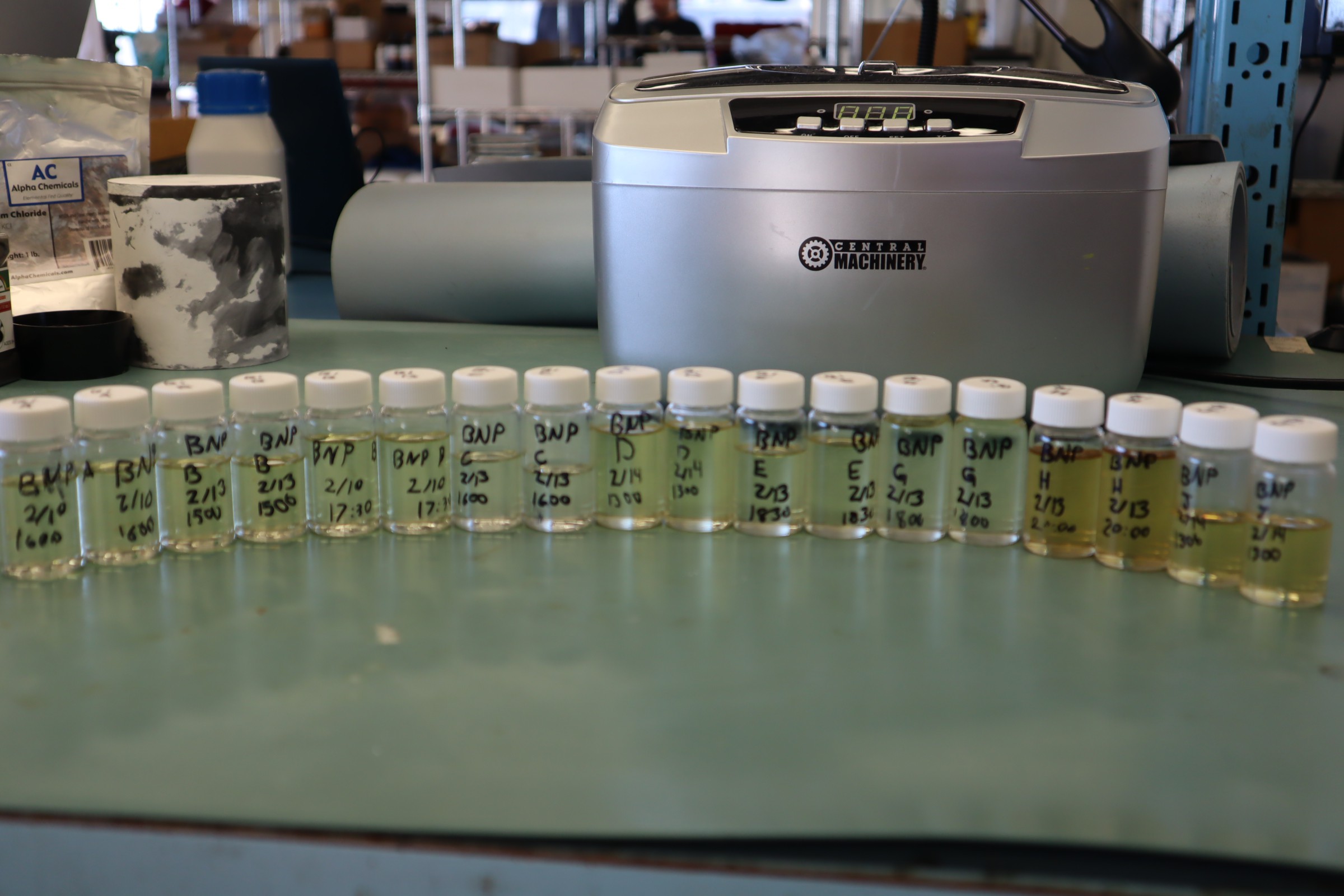
fig 5: Bismuth nanoparticles soon after being synthesized
This success was the basis for further nanoparticle production,
though there were some small changes in each iteration that we did to
try and simplify the procedure and increase the purity of the
nanoparticles. We started adding excess ammonium formate to increase
the purity of the nanoparticles, eliminating more of the reactants.
We tried using magnesium to encourage impurities to fall out of
solution, but ultimately the potential of increased salt impurities
made that less ideal.
We also concentrated the nanoparticle solution further for use in the high temperature thermionic device. In theory, the more concentrated the nanoparticles, the more effective the device would be. Subsequent batches of the nanoparticles also used H (Diaminododecane) and E(Dodecanol) as surfactants, as these were deemed most ideal for our use in the thermionic device.
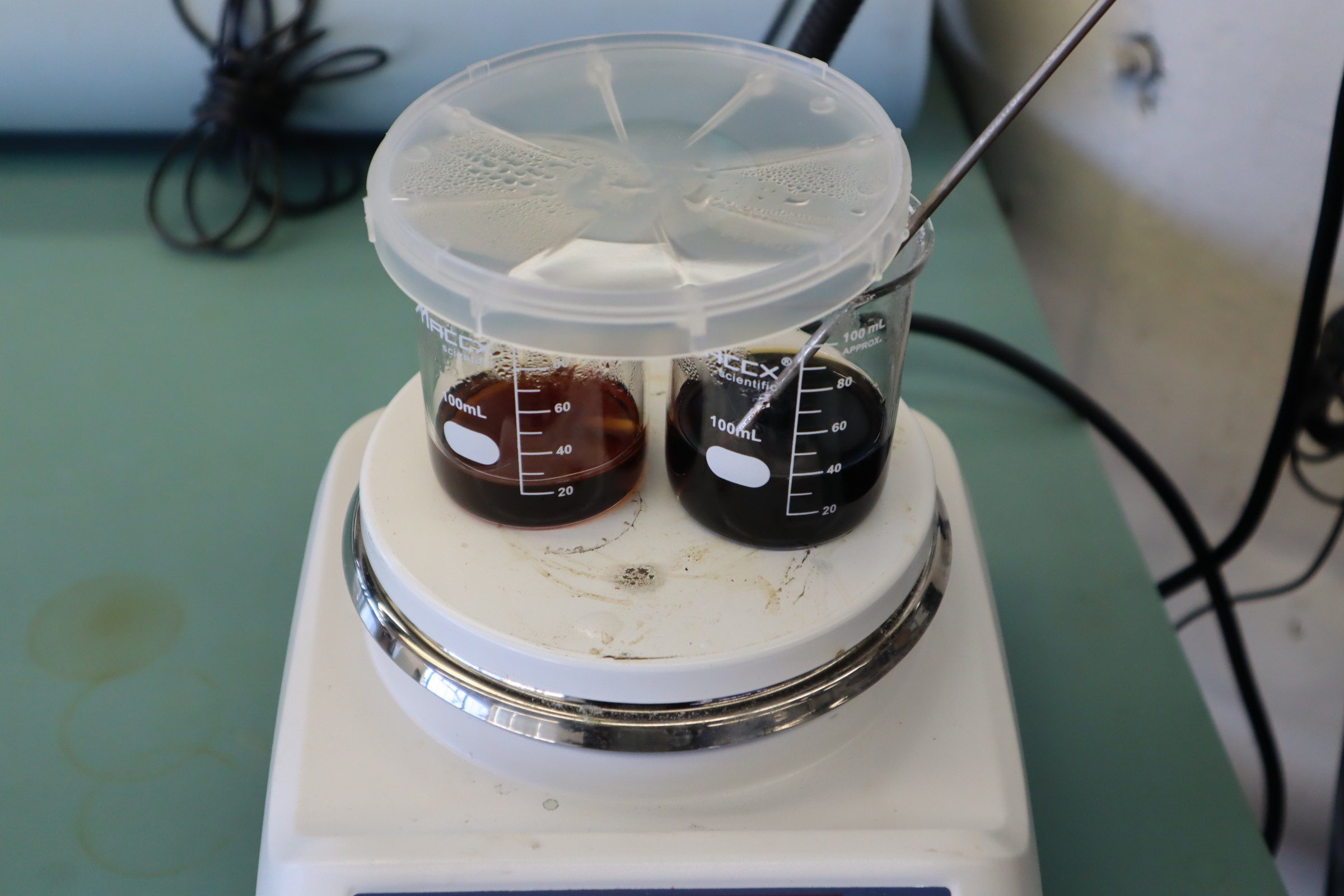
fig 6: concentrated nanoparticles
Separation Film Preparation
For the high temperature thermionic device, we needed a thin separation between the plates, to avoid them contacting and shorting out the device. We also need parts of that space to be unobstructed so the nanoparticle solution can fill in the gap and allow for the function of the device. The needed gap is small enough for it to be impractical to hold the two sections apart. We instead used a thin (2 micron) film for the separation.
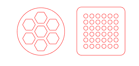
fig 7: geometry of the cut film
This film blocks the functionality of the device, so areas need to be cut out in order for the gap to be maintained without completely blocking the intended movement of energy. We started with a hexagonal honeycomb design, as seen in figure 5.
Figure 6: Geometry of the cut film
After using the film on one of the devices, we determined that
it may be easier to use a rounded square with circles in a grid
pattern. This would make it easier to remove wrinkles from the film
without warping or ripping it.
In order to cut the film, we used a Silhouette Cameo 4. We first smoothed the film onto a sheet of cardstock paper, using a solution of 25% pine sap and 75% limonene by weight. Making sure to get all the wrinkles out, we then allowed the film to dry overnight on a flat surface, under the even pressure of a large book.
We then used self-adhesive velum to mount the film for cutting on the machine. This was done by peeling the velum off of the backing paper and carefully replacing it with the cardstock/film combo, with the film sandwiched between the backing paper and the cardstock, with the cardstock being roughly centered on the larger backing paper. The velum is then reapplied to the backing paper, sticking to the cardstock as well and holding it in place for cutting.
The resulting sheet was then loaded into the cutting machine with the underside of the backing paper facing upward. For the cutting itself, the machine had a 1mm manual blade installed, with a blade depth of 3 and a force of 20. We did one pass at a speed of 4. This was enough for the film to be cut through, without cutting through the cardstock completely as well.
While doing subsequent cuts, we determined that mounting the film between a sheet of cardstock and printer paper can eliminate the need for velum. When cutting this way, the film is first spread on a sheet of cardstock using a solution of roughly 50% pine sap and 50% limonene A sheet of standard printer paper is laid over it, and the edges are taped. This can then be run through the printer at the same settings, with layers fed into the machine with the printer paper facing up.
This simplified procedure can result in some of the lines not cutting fully, but the resulting film is still useable and it eliminates the need for drying time and separate velum papers. These missed cuts are due to delamination between the film and paper layers. Possible improvements could be done through changing the adhesive and/or paper used in the process. Another way to mitigate this issue is to do a second pass through the cutting machine.
Discussions
Become a Hackaday.io Member
Create an account to leave a comment. Already have an account? Log In.