 Emilio P.G. Ficara
ColorLamp
This device does not have to be built, just buy a module (USB dongle) on the Internet and download some free software. Let's see the module (actually, there are two). You can use both, because in the attachment that you will find at the bottom of the article, there are two distinct versions of the firmware.
Both modules are small HW development platforms for Nordic's nRF52840 chip (to see how interesting it is, I recommend visiting the manufacturer's website ). I used this component for the first time in November 2018, while I was on business in Germany. I found a project started and to be finished and I had to study everything, because I did not know neither the micro, nor the development environment. It wasn't easy, but in the end I made it and developed other interesting things as well. The development environment was based on the Zephyr platform (RTOS created by the Linux Foundation) which since then I continue to use for my programs even here in Italy, where I returned last summer and where I am now (I hope temporarily) blocked due to "restrictions". I installed the Zephyr and the Nordic development tools on a Linux Ubuntu VM and it works well even with a "scarce" laptop with 4GB of ram in all.
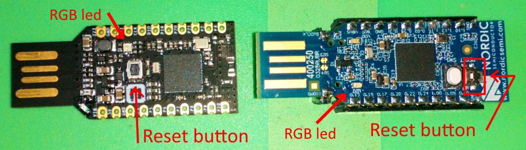
The module on the right is a product of Nordic itself and you can find its characteristics at this link . The other, on the other hand, is a product whose characteristics are described at this link and also here, where there is a substantial documentation. The Nordic model I bought from an electronic component supplier, while the second I bought on "a well-known online sales site starting with A". I thought the second was a clone of the first but not. The corresponding I / O (but in different positions) are only 4. On the Nordic there are more: 3 I / O lines, a programmable LED and a button. On the other is a 3.3V voltage regulator with more than enough current to power various additional peripherals. The second module has all the pins on the strip connectors, while the Nordic has two signals "out", but always at a pitch of 2.54mm close to the USB connector. These signals are SWDCLK and SWDIO which are used to connect a J-Link interface. In the other module, we find the same signals (plus an external reset) on the strip connector and therefore we lose the 3 I / O lines. The voltage regulator of the Nordic, however, despite being programmable, supplies very little current (about 30mA and also feeds the internal circuits) and therefore I usually put an external regulator in my projects that foresee peripherals at 3.3V.
To program the flash memory of the module (both one and the other) we need a software that we find on the Nordic website at this link . It's there for Windows, Linux, and Mac, so you can install it anywhere!
Once installed, we will need to add the programming section. The software is truly "vast" and full of potential, but let's proceed step by step:
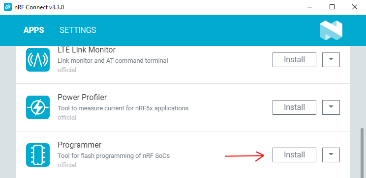
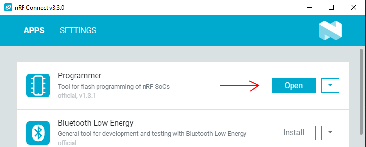
Click on Install and we will have our programmer ready to use:
To program the modules, just put them in a USB port on the computer where the program was installed. Inside the firmware, in both modules, there is a specific BOOTLOADER that allows you to modify the programs present. Of course, when writing your own firmware application, you have to be careful not to end up in the memory areas occupied by MBR and BOOTLOADER. If you do, the micro can only be reprogrammed with a J-Link interface! However, with my firmware that you find at the bottom of the article, you are not in danger.
Program the module
Well, how does this work? In summary, when the module is reset by Power-On, the user's App is executed, while if the reset comes from the small button (see where it is located in the first photo above) then the programming / update mode is started. This mode, in both modules, is highlighted with the RGB LED flashing red, turning on and off with a dimmer effect.
The Nordic module is supplied without any user App and therefore as soon as it is powered it goes into programming mode. The other, on the other hand, already has a user App (which you will lose if you reprogram the micro) and therefore starts with that one, so it will be necessary to power the module by holding down the reset button to send it to programming mode.
So: we downloaded and installed the Nordic software and also my .zip file that contains the App for Android (we will see it later) and the .hex files to program the Nordic module or the other (suffix "geek"). We insert the module into a USB socket on the computer:
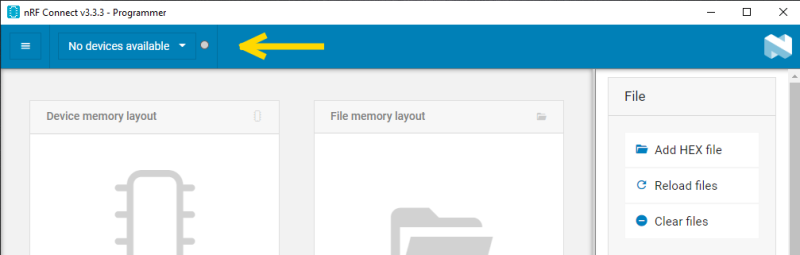
If we see this, the inserted module is not in programming mode. We must therefore reset it using the button. As soon as it is reset and entered into programming mode (red LED flashing) we will find ourselves in this situation:
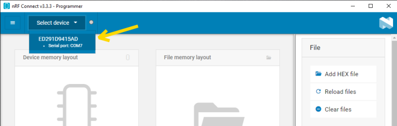
Here it is, the module is now seen as a Serial Port (in my case, Com7). We then click the button and we should see this:
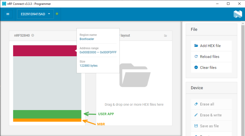
Here is the mapping of the flash memory of the micro inserted in the USB port. Moving the mouse over the various areas we will have additional information. The MBR and BOOTLOADER areas are critical for the device to be reprogrammed with this method. If you make a mistake and overlap your program to one or both of these areas, it will be possible to reprogram the device ONLY with an appropriately connected J-Link interface. However, you can only make this kind of mistake if you develop the application yourself. In this case, everything is designed not to damage the MBR and BOOTLOADER. If we have downloaded the firmware files, we select the one that interests us. Obviously, the firmware for the Nordic does not fit on the other and vice versa, due to the different mapping of the RGB led on board. Note that on the Nordic there is a second LED (green) which is controlled via software, while in the other module the same green LED is connected directly to the power supply and therefore will always be on. Let's now choose the firmware version:
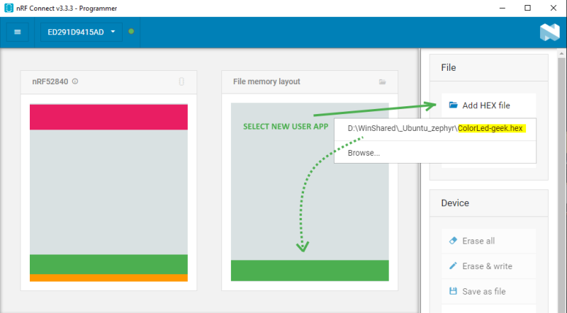
As soon as the file is chosen, we will see that the memory area occupied by the loaded App appears in the map on the right. If we hover over it with the mouse we will see this:
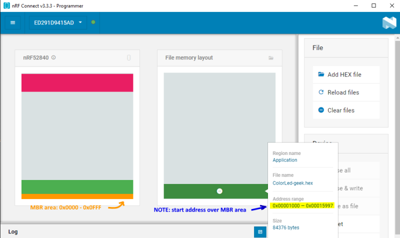
As shown in the figure, the memory area of the App is located exactly above the Master Boot Record (MBR) and therefore preserves it. At this point, between the buttons on the right we will click " write " and nothing else . Programming is fast and immediately after the micro restarts and then exits the programming mode, running the firmware just inserted. As a result of this, the Serial Port disappears from the system and we will see this image:
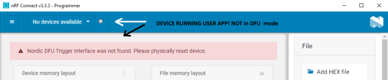
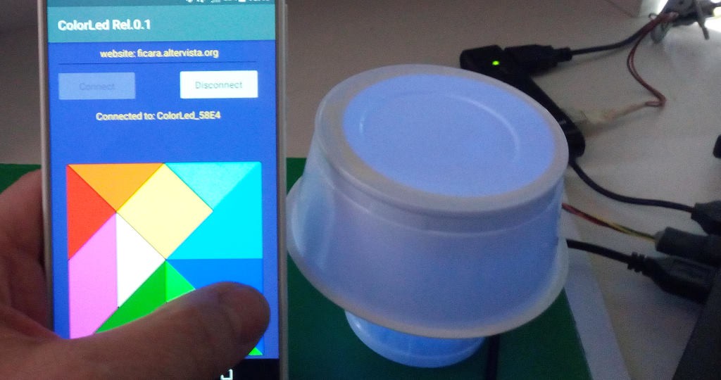
This is all normal. Now the module is running the new firmware called ColorLed (-geek or -nordic version) and uses the PWM on the three channels of the RGB LED and Bluetooth to control the color via an App for Android.
The APP for Android
This App, which I wrote with the Anywhere Software B4A software tool (I've been using it since 2011; before it was paid, now it's free!) Allows you to control the RGB LED color via Bluetooth. I tested it on two phones and a tablet with Android versions 5, 7 and 8 and with different screen sizes. Here is the app icon (minimalist):
To install it, since it is not on Google Play, you need to check the box "install from unknown locations" in the phone's security settings. Once the App is installed and launched, we will see this:
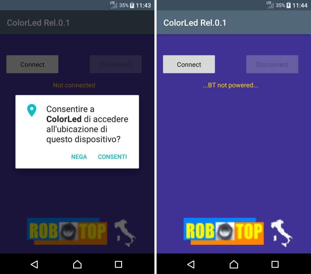
On the left we see what happens in Android versions from 6 onwards: we are asked for an authorization for geolocation. This is due to the fact that (although I don't understand why), to use Bluetooth, geolocation must also be activated. If not, it doesn't work. In the Android 5 version (my old Huawei) the authorization is not requested, but you must ALWAYS activate the geolocation, in addition to Bluetooth, to have the App working. In the screen on the right we see what happens if the Bluetooth is not turned on: we are notified with the message “… BT not powered…”. Now let's see what happens if everything is fine and Bluetooth is turned on:
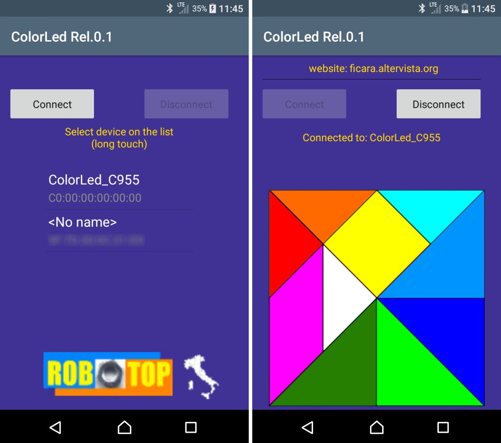
On the left we see what happens when we press “Connect”. A scan of the various Bluetooth devices that can be reached is performed. A ColorLed_xxxx will appear in the list where xxxx are the last 4 digits of the device_id which Nordic puts (is not editable) in all nRF52840 chips. This code is not unique, but it is specified that the possibility of finding two identical ones is very low. In any case, it is only needed if you have more than one ColorLed unit "visible" from your phone. Long click on the list item you want to link to and (hopefully) you will see the image on the right. Tapping on the color map (a bit unusual, but the classic "wheel" got bored) you will see the RGB LED on the module light up accordingly. On the Nordic, you will also see the single green LED light up with each command received from Bluetooth, while on the other you will not, because this LED does not exist.
Just as a "historical" reference, I also propose the first LED control circuit I made with an Android tablet back in 2011. I found the video on an old backup disk and put it on the internet…
Conclusions and annexesThat's all. In the attachment you will find, zipped, the .apk file for the smartphone and the two .hex files for the modules (one with the suffix -nordic and the other -geek). the zip has a password which is: eficara. Always check the SHA-1 code to be sure that the file is intact and not manipulated by others. In this case the hash must be:
SHA-1: 4D7B781B77E67BF58172F6ECEEF0B907A0847DA6
The zip is available in the "files" section, as usual.
I remind you that I take no responsibility for any problems that may arise with the download and / or installation of the material made available. It is material of a hobby nature and made available free of charge, so you, by using it, take full responsibility. I am not an expert on legal terms, but I hope the concept is clear enough.