 DIY GUY Chris
You will certainly learn something new in this post : )
Here I am again sharing a live experience through this Gym gadget device that I designed and built by myself in order to solve a daily life obstacle.
During gym sessions I spend some of my time discussion with my coach trying to convince him that the current set is the final one, by his turn he try to convince me otherwise and this will keep me thinking about what is the exercice's sets target and how many ones I already completed, from this corner it comes the idea of producing an electronics gadget where I can precise the exercice sets and I indicate how many sets I already did, the gadget has to be wearable and compact as maximum as possible.
What you will learn here:
- The basic circuit setup for Atmega328pb MCU
- Some Electronics designing tips
- The advantage of use of WS28xx LEDs
- How to produce a compact electronic device
Supplies
The needed tools:
- Solder Plate (You can use the Uyue 948S+ model)
- Solder Iron
- Low temperature Profile solder paste (CHIPQUIK SMDLTLFP10T5)
- Solder paste deposit spatula
The needed software:
- Altium designer as ECAD for PCB drawing
- Solidworks as CAD for housing designing
- Cura as slicer for 3D printing
- Arduino IDE
Note: You can download the necessary CAD files from article links, all download links are freely available.
Circuit Overview
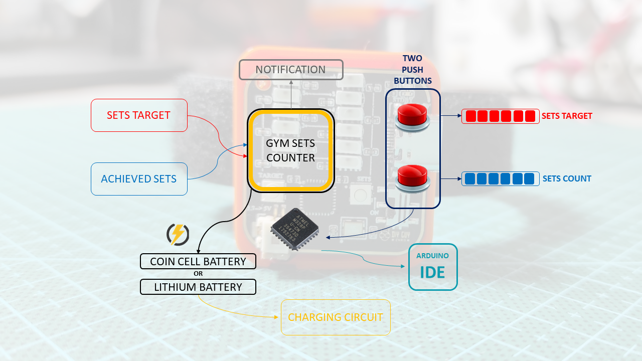
Before getting to the technical details of this gadget, this device will not automatically count the sets but it keeps track of the achieved sets so you need to set manually the sets target and how many sets you did.
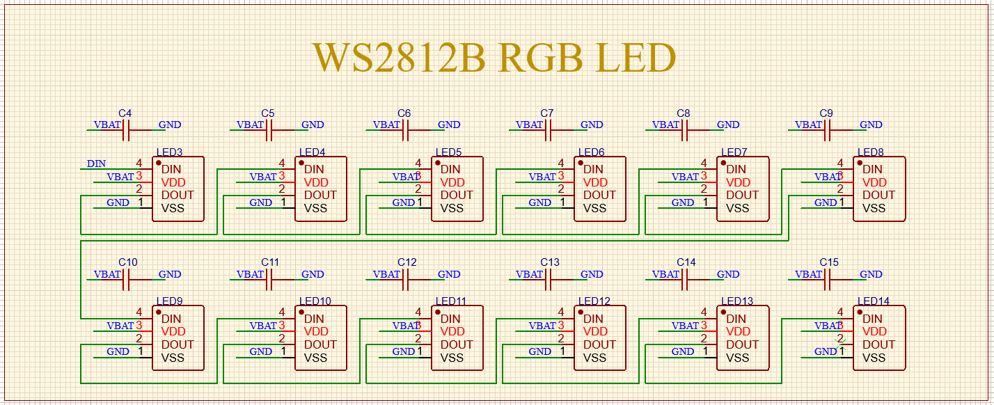
The circuit around this design is so simple, two push buttons are needed to increment the counter for the target sets and the done sets, since we are incrementing counters then we need a display tool for these counters and here it comes the role of WS2812B LEDs, I arranged 12 of them in two LEDs bars (6 pixels each) mean the counters will count to 6 for both the target and the achieved ones.
The circuit has been built around Atmega328p MCU but you can use whatever microcontroller of your choice as long as you keep a compact size for your circuit design.
The device will be powered through a Coin cell Battery or Lithium 3.7V rechargeable Battery and for this purpose we will add a charging circuit stage based on TP4056 IC.
I manage to program the MCU using Arduino IDE so I make sure that the Atmega328 that we are using already has Arduino bootloader in it.
Circuit Design![]()
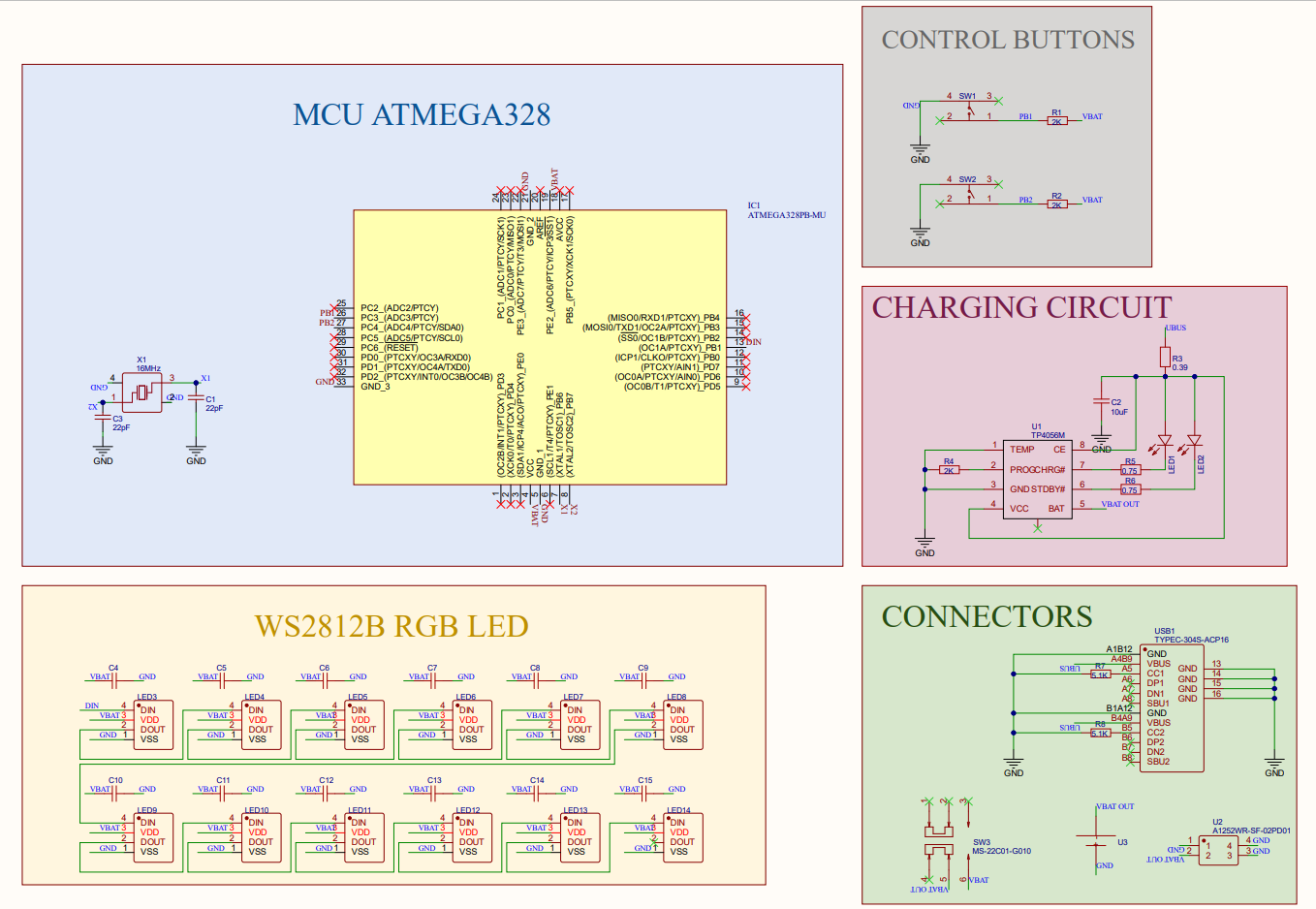
Probably the main and most important part of the schematic is the Atmega328PB that I used, it has the smallest package 32 MLF which is important to keep a small size needed for the circuit, I used Octopart to bring all the needed components for the schematic and it is truly handy online tool allowing you to download CAD files of components for several ECAD tools like Altium Designer which is the Designing tool that I used to create both the schematic and the PCB design, you can start your free trial of Altium designer through this link.
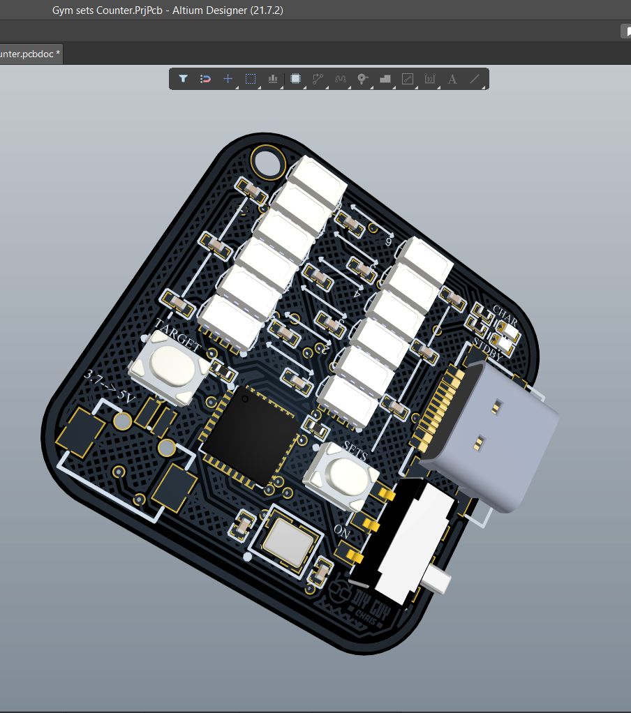

I also attached the MCU datasheet provided by Microchip, I connected two tactile push buttons to my MCU and used one Digital output to control the 12 WS2812 LEDs, these LEDs are connected in series but it has to be arranged in the PCB layout in two columns (starting from pixel 0 to pixel 5 for first column then from pixel 6 to pixel 11 for second column). I placed a USB C connector to the edge of the design and I will use it for power battery charging.
You can also download the shematic PDF Files below.
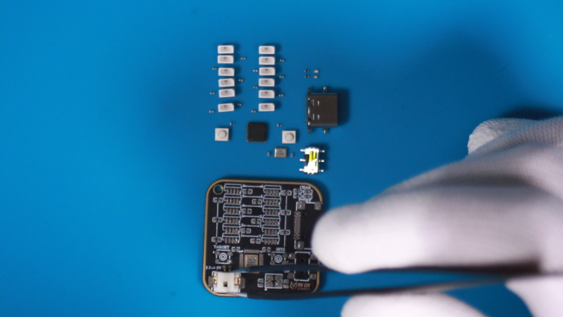
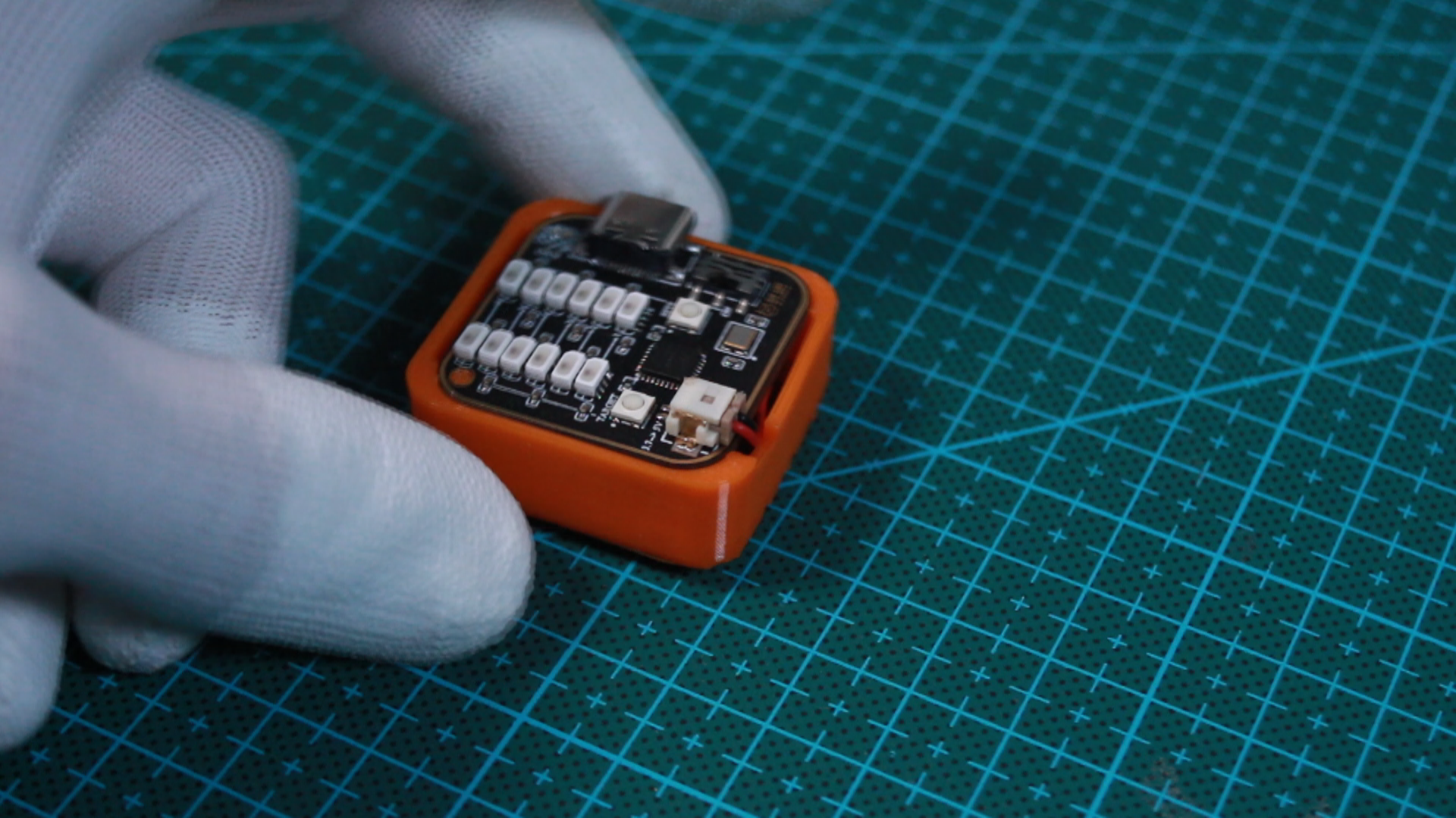
Now We Assemble
This is the most amazing step you know! I truly like electronics assembly : )
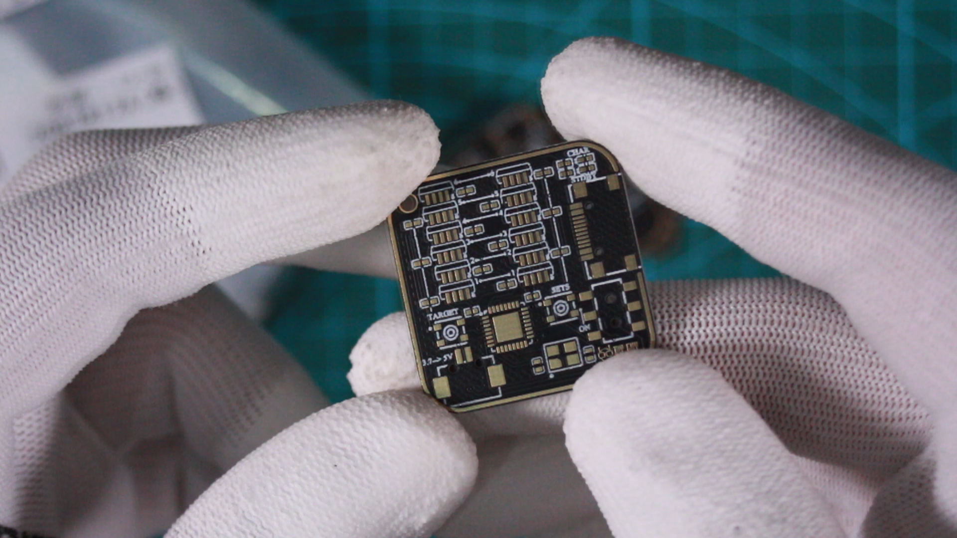
Before starting any further process let me explain the procedures of the PCB design ordering, any ECAD tool has the ability to generate the design related GERBER file that you will need to place a PCB order, basically all PCB manufacturers require this GERBER to produce your board.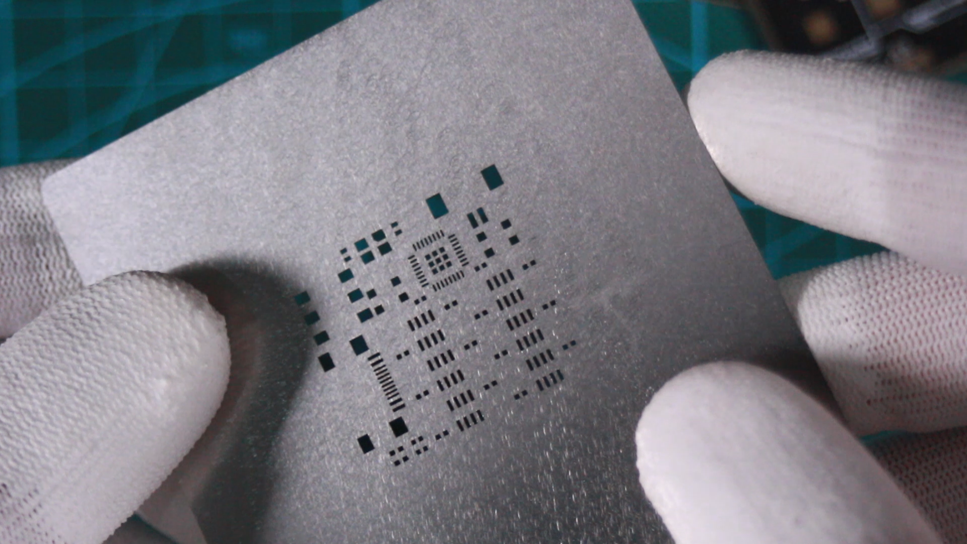
Our design is a 2 layers board design and it has a very compact size of 30 x 30 mm, I moved to JLCPCB where I uploaded my GERBER files and placed a PCB order along side with its stencil.
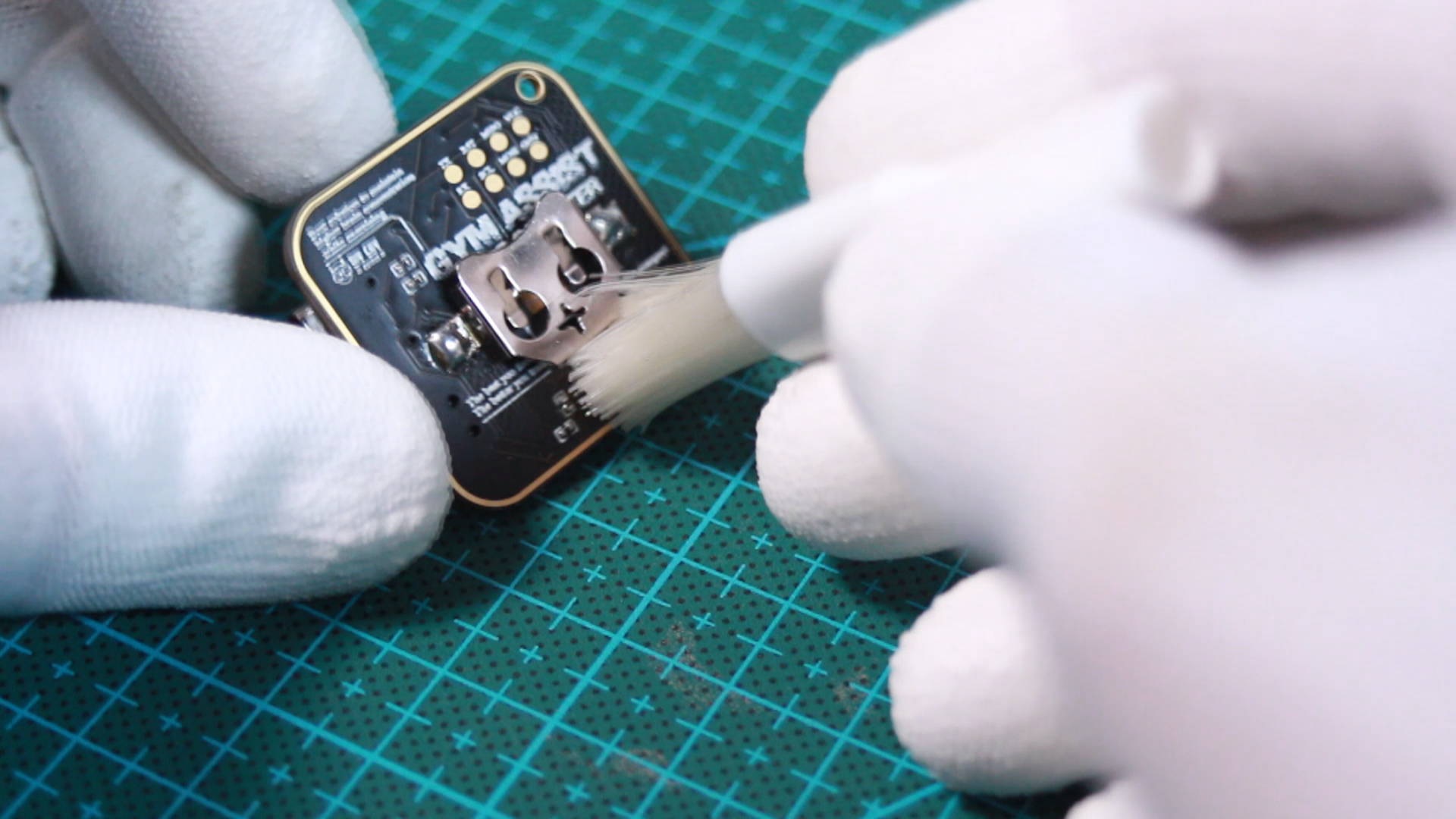
I used a low temperature profile solder paste to get it work properly for assembly using my Hot-plate. Make sure that you clean your assembled board with some flux removal solvent after finishing the parts soldering.
Arduino Code

As I mentioned from the begining of this projust, the MCU selection is based on the software programming tool which is the Arduino IDE, I used the Adafruit Neopixel library to get access to the WS2812B Pixels, I defined the LEDs control pin as Digital pin 9 since it is the one that we used in our schematic, then I defined Two digital pins D3 and D4 as digital inputs where I connected my push buttons.
The program startup with a quick animation of color rainbow then every click on the push buttons will light up a pixel, as soon as the Sets pixels get equal to the Traget pixels then the Pixels will display again the quick animation of the rainbow colors to indicate that the exercice is done achieved and we move to the next exercie.
I used PoGo pins of my PCB design to upload the code through ICSP Port.
All detailed through the Code file.

CAD for Housing
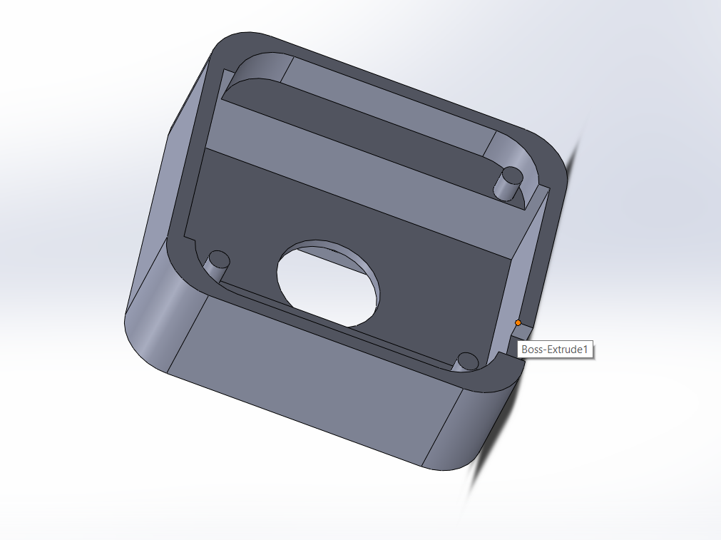
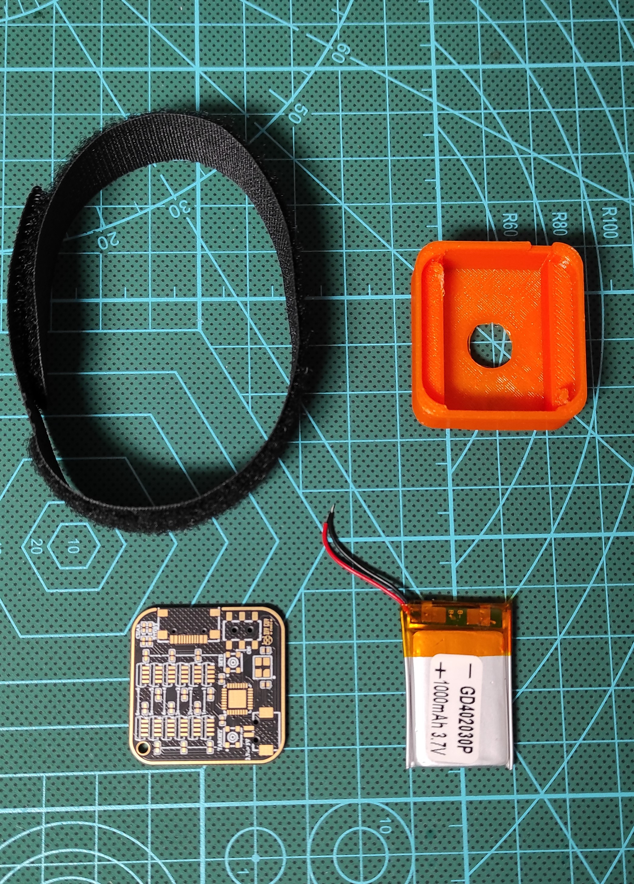
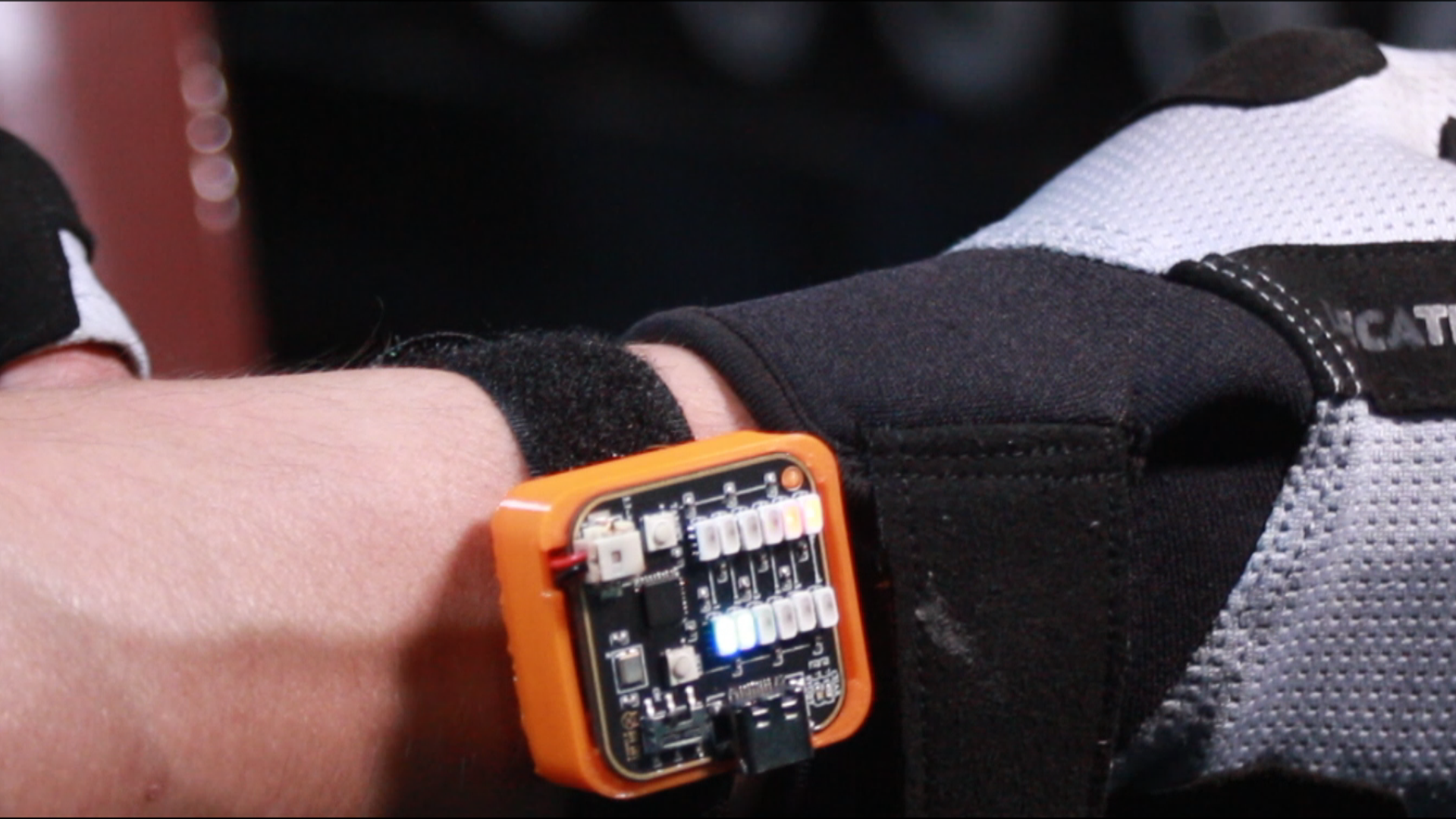
After completing the programming step here I design a small flex housing to make my gadget wearable.
I 3D printed the designed housing in Flex material and now the gadget could fit properly to my hand. 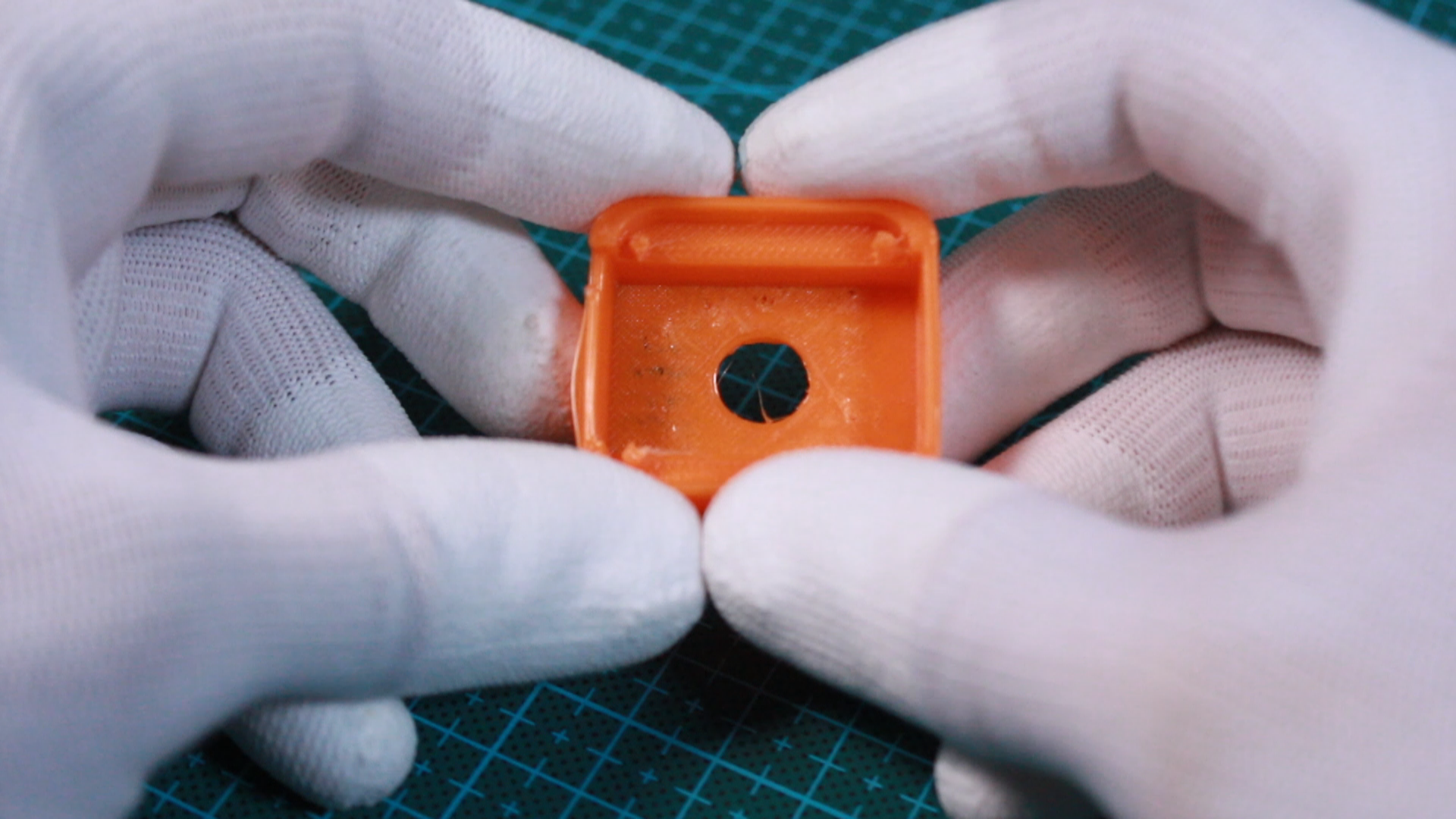
Final Assembly and Test
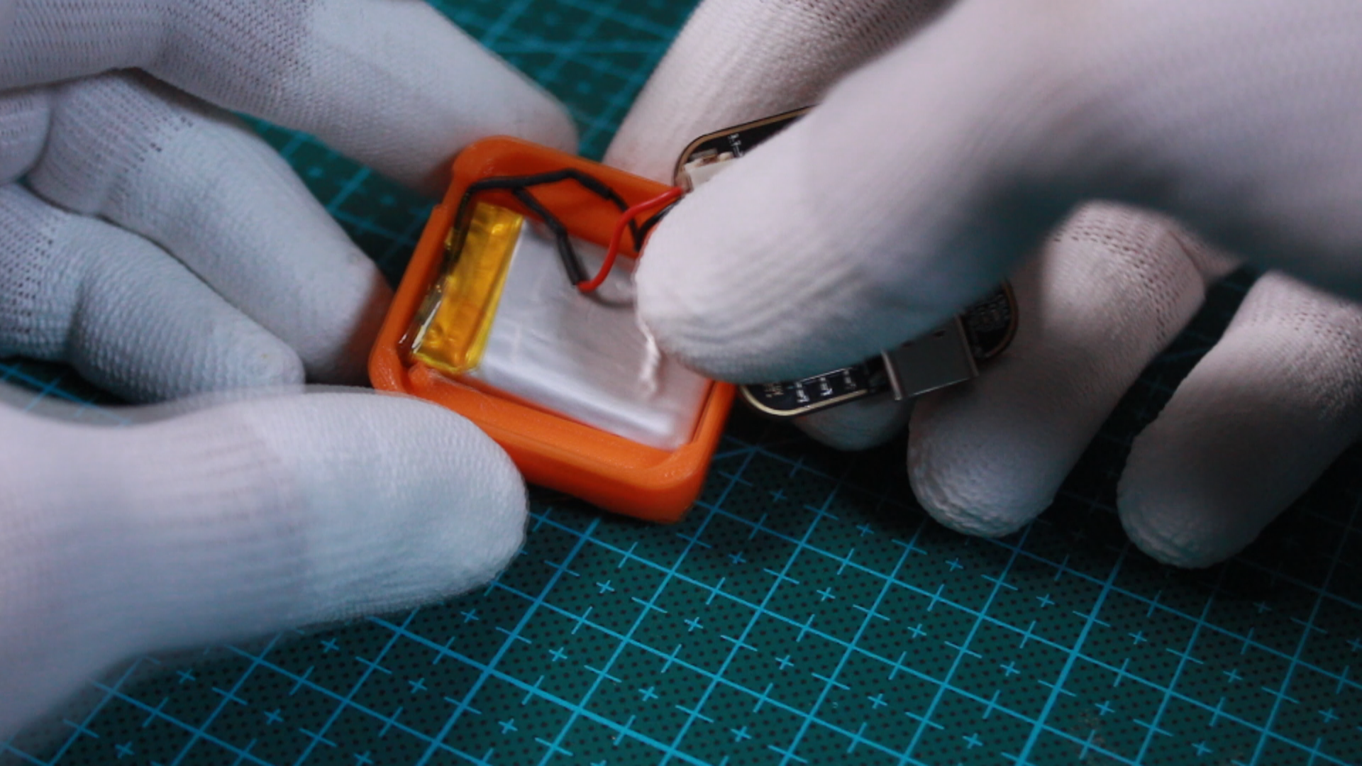
All what it needs now is finishing the scratched bracelet placement and I can wear my gadget and take it straight to the Gym.
That's it for this project, I hope you enjoy it and let me know your thoughts in the comments section : )