Emilio P.G. Ficara
Stepper motor tester and BLE Android App
Here is another application of Nordic's USB dongle with the nRF52840 SoC. In this case, the module is used, together with a suitable control circuit, to control a stepper motor. All information on how to program the module with this application can be found in this article.
Hardware
Let's see the wiring diagram right now:
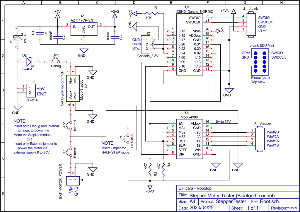
For a more detailed and clear view, you can download the original steptest-sch.pdf from “files” section.
The main component is, of course, the module with the SoC (System on Chip) nRF52840 from Nordic. However, having to drive a stepper motor, I added another module that acts as a power driver and I found one ready, based on the Allegro 4988 chip. This driver allows you to have different options on the motor driving, but I only used the JP4 jumper for the choice, limiting the driving to Full step (without jumper) or Half step (with jumper) modes. Another feature of this driver is that the voltage for the motor ranges from a minimum of 8 to a maximum of 35Volt. For my tests, I use small motors that run well between 9 and 12Volt and then I added a step-up DC voltage converter to use only one supply (5Volt) for the whole circuit.
On the diagram we also find the connector for the bipolar motor (4 wires). If we have a unipolar motor (3 wires per winding, with central socket) we can still use only the two external wires, ignoring the central one (valid for both windings).
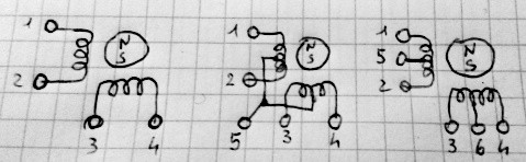
With the driver used in this circuit, only wires 1,2,3 and 4 are used. If in doubt, to determine which are, measure the resistances between the various wires with a tester.
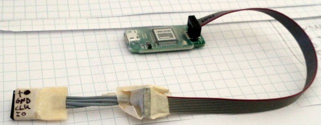
Then we have a connector for J-Link interface and for a serial console (via USB-serial converter at 3.3Volt). To program the module, the J-Link interface is not needed, you can insert the firmware through the USB connector of the dongle itself, as explained in this article. If you still want to use the J-Link interface, I recommend the J-Link EDU Mini model by Segger. I have also experimented with some "clones", but the original costs only a few dollars more and has all the drivers guaranteed and debugging support working 100%. The only critical thing is the small output connector, which forces you to make a "home made" adapter to go to the classic 0.1″ step used in prototype boards. I did it like this:
On the hardware side, since all commercial modules are used, there is nothing special to say. For the step-up DC converter, I recommend calibrating it for the desired voltage (there is a trimmer on board) before connecting it to the circuit. Obviously, the external 5 Volt power supply must be able to "withstand" the load of the circuit and the motor. The step-up DC converter I used is declared to have an efficiency greater than 77% and a maximum current of 1A, so it's fine for small motors. I used for the tests a 5V-1.5A power supply and a ULM-15 stepper motor with 24 (full) steps per revolution. The step-up DC converter is rated for 10V output. I also selected Half-Step mode with the JP4 jumper, so 48 clocks are needed for one full revolution.
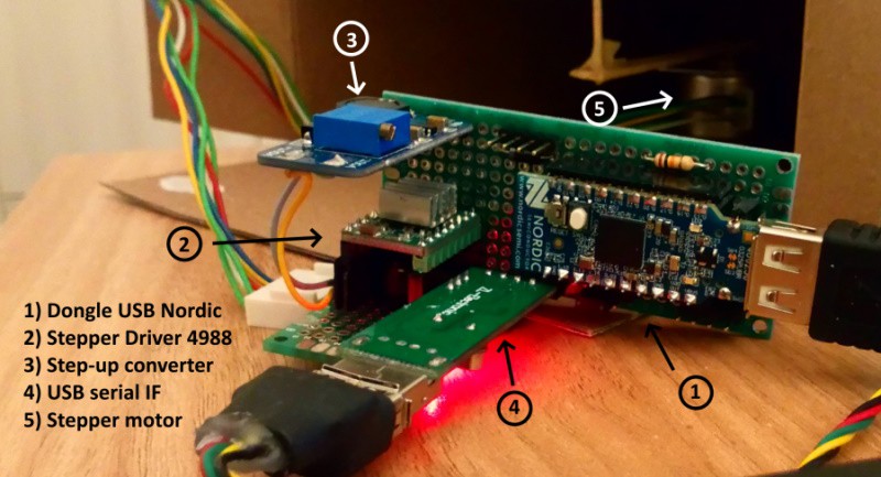
In the video that follows, here is the circuit in operation. To make things more fun, I put a small magnet on the motor shaft and closed everything in a box; then, I took a paper clip and glued it on a piece of paper on which I drew a toy car and so, when the engine is running, the paper clip is pulled by the magnet and it looks like a car on the track!
Below is an old mechanical prototype, built with Lego, in which a model 28BYJ-48 geared-down stepper is used. You see 5 wires on the connector, but as we said, only 4 wires are used. Note that the circuit presented in this article is NOT appropriate for stepper motors running at 5 Volts. The 4988 driver, in fact, works with a Vmot from 8 to 35Volt and below 8Volt it is not reliable or does not work at all. For very low voltage stepper motors (3 or 5Volt), I suggest using the usual ULN2003 (in case of motors...
Read more »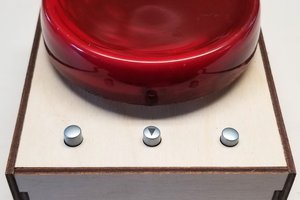
 Dave Ehnebuske
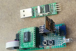

 Andrew Kotite