 selena1995
HOW DOES A SELF-BALANCING ROBOT WORKS?
Self-balancing robots use a “closed-loop feedback control” system; this means that real-time data from motion sensors are used to control the motors and quickly compensate for any tilting motion in order to keep the robot upright. Similar self-balancing feedback control systems can be seen in many other applications.
WHERE ARE SELF-BALANCING ROBOTS USED?
Among wheeled robots, two self-balancing robots, the Segway and Ninebot, have become popular and are used for commuting or as patrol transporters. In addition, self-balancing wheeled robots such as Anybots QB are currently used as a service robot platform.
WHICH COMPONENTS WILL BE NEEDED AND WHY?
Here in this part, we will discuss the components, why we did choose them, and side by side we will make the robot too.
for a better explanation, I have divided this into three different parts-
- Mechanical Part:- here we will learn to make the robot body in a very simple and easy way.
- Electronics Part:- here we will learn about the electronics components, circuit designing, and assembling all the components. end of this part, our robot will be ready to go for the next and last level which is Arduino coding and calibration.
- Arduino Coding & Calibration:- Here in this last part, we will discuss the Arduino code and how to calibrate the robot for self-balancing.
After completing these three steps, Our robot will be ready to show.
MECHANICAL PART
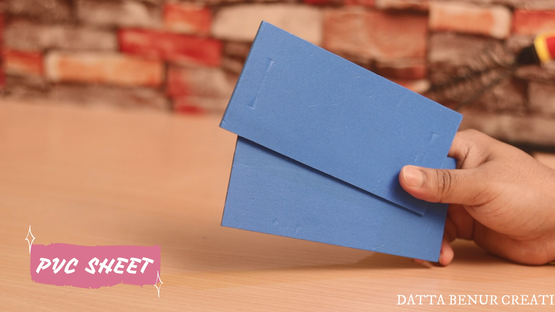
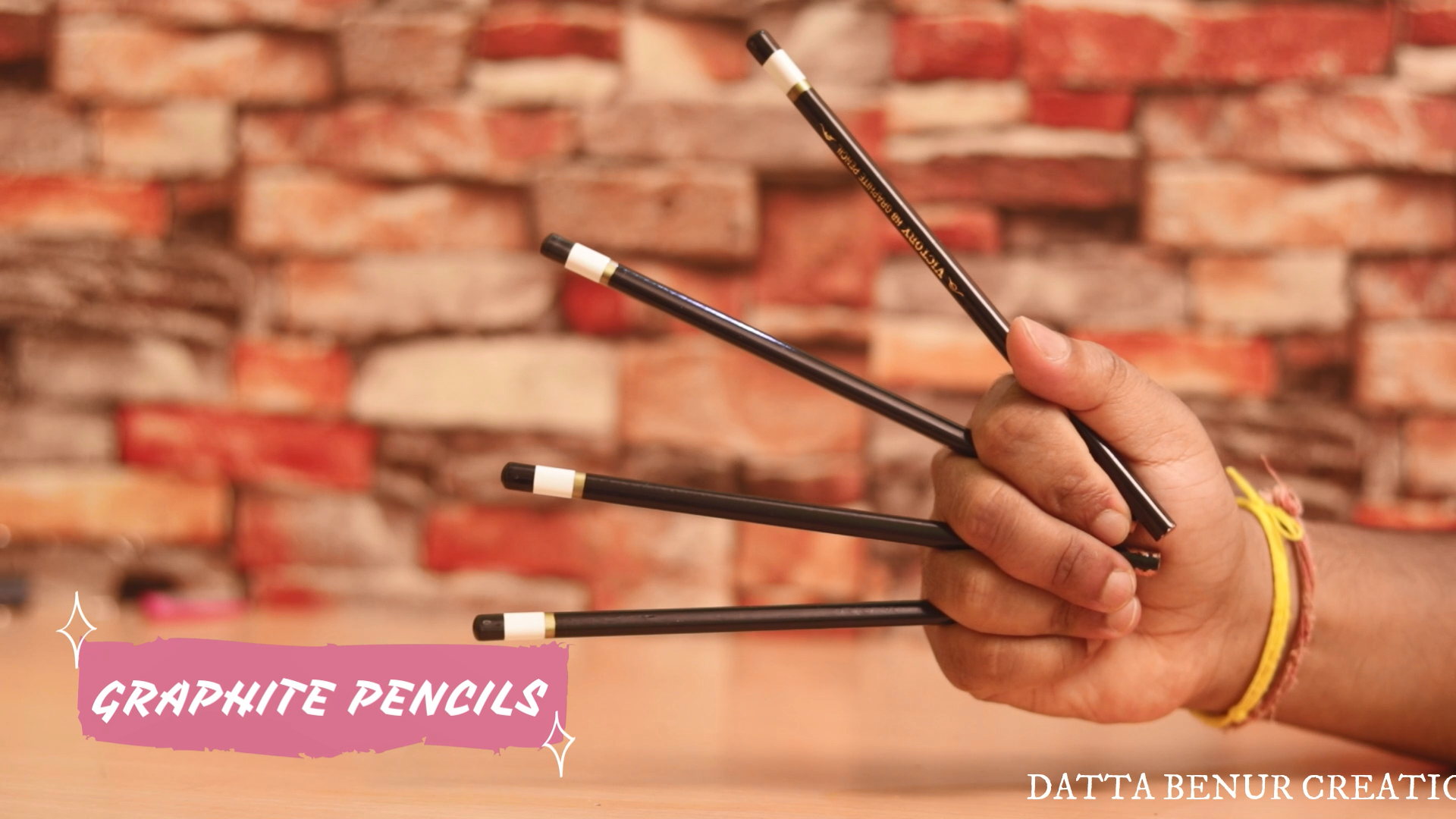
We will start making our mechanical part first. For this, l have used some PVC sheets and 4 no of Graphite Pencil to make the robot Body. Please make the robot multi-storied because we are going to use mpu6050 which works best if it is placed at some height upper than the base. We will discuss more on mpu6050 in the later part of the electronics part of this article. For now, we will go for the mechanical part only.
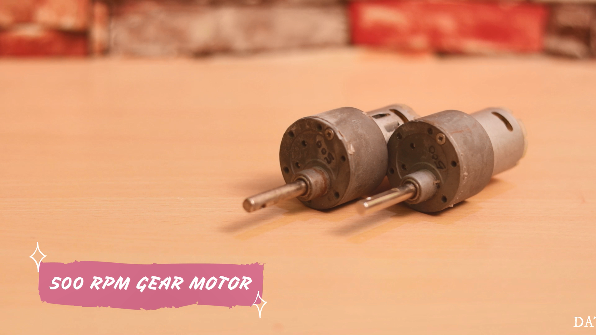
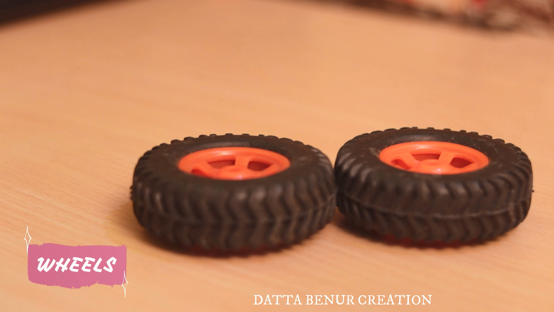
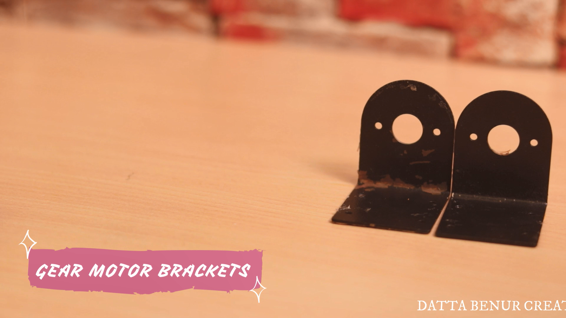
After that, we will need two no of gear motors, two motor brackets, and two wheels.
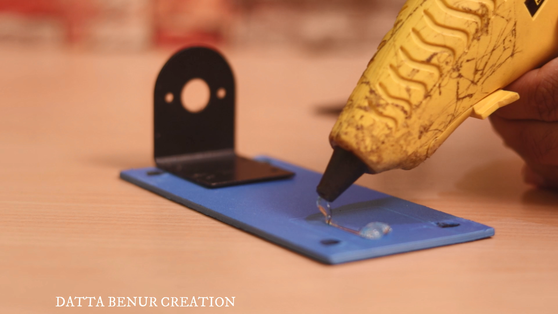
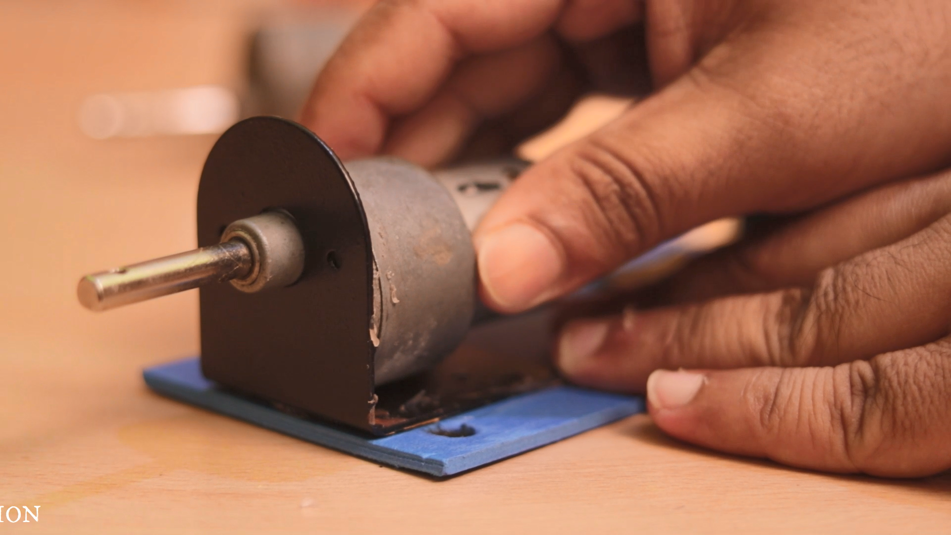
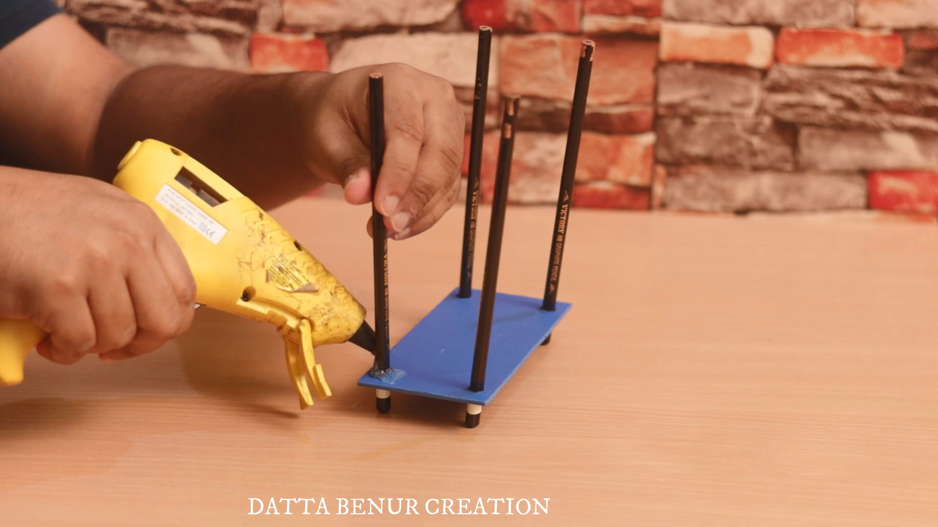
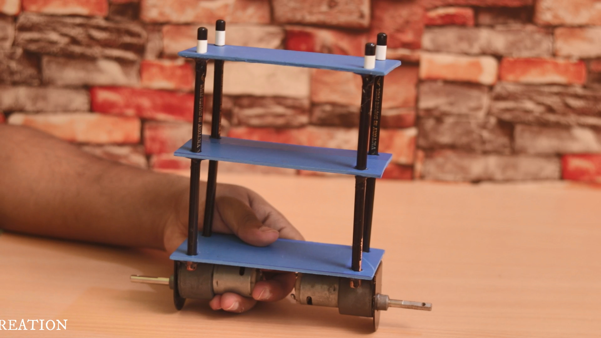
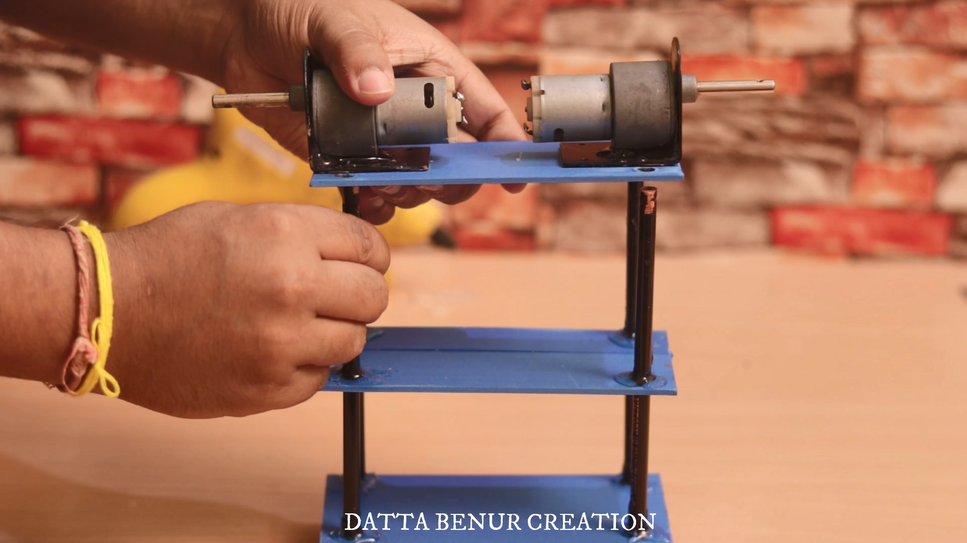
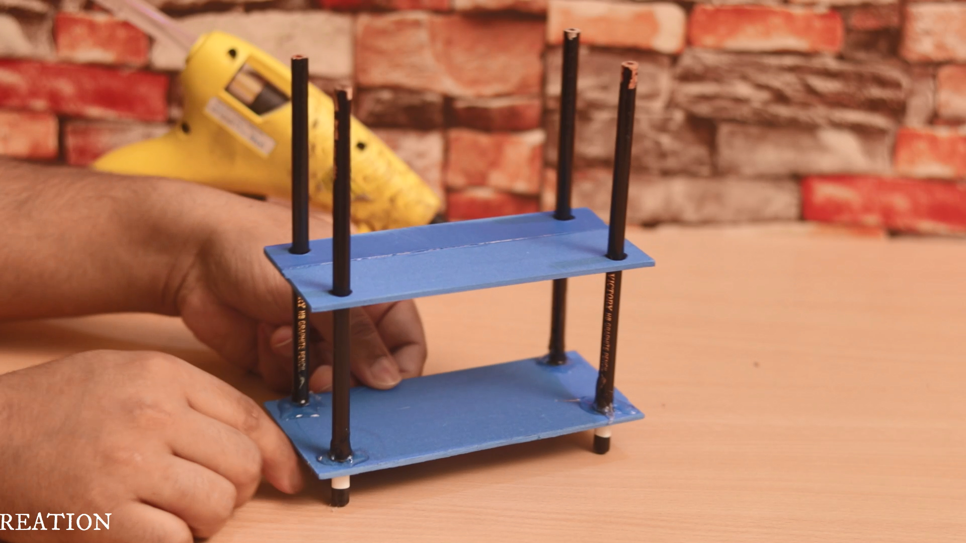
I have used hot glue to attach all the parts together. It will take not more than 20-25min to give it a perfect look like this. Our mechanical part is ready and now we will go for the electronics part.
ELECTRONICS PART
In this part, we will discuss the electronic components that we have used to make this robot. We will also learn why have we chosen all these components. Here we will also connect all the components together according to the circuit diagram that l have already attached with this article. Please download it before you are going to connect all the components together.
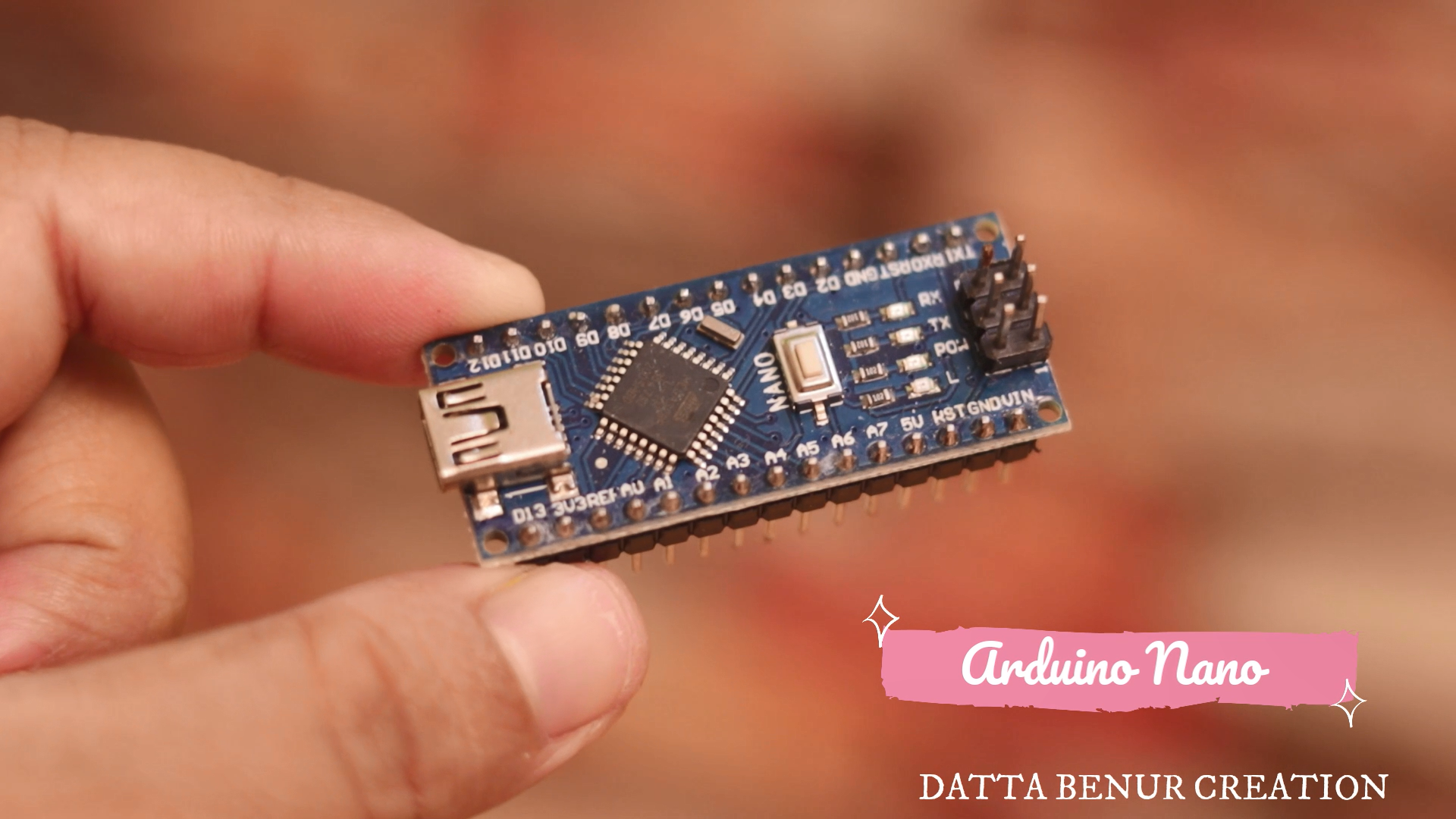
ARDUINO NANO
Arduino NANO is the brain of the robot. Here l choose it because It's a perfect micro controller to learn hobby electronics and programming on, and its size makes it excellent for building into projects which require a small form factor.
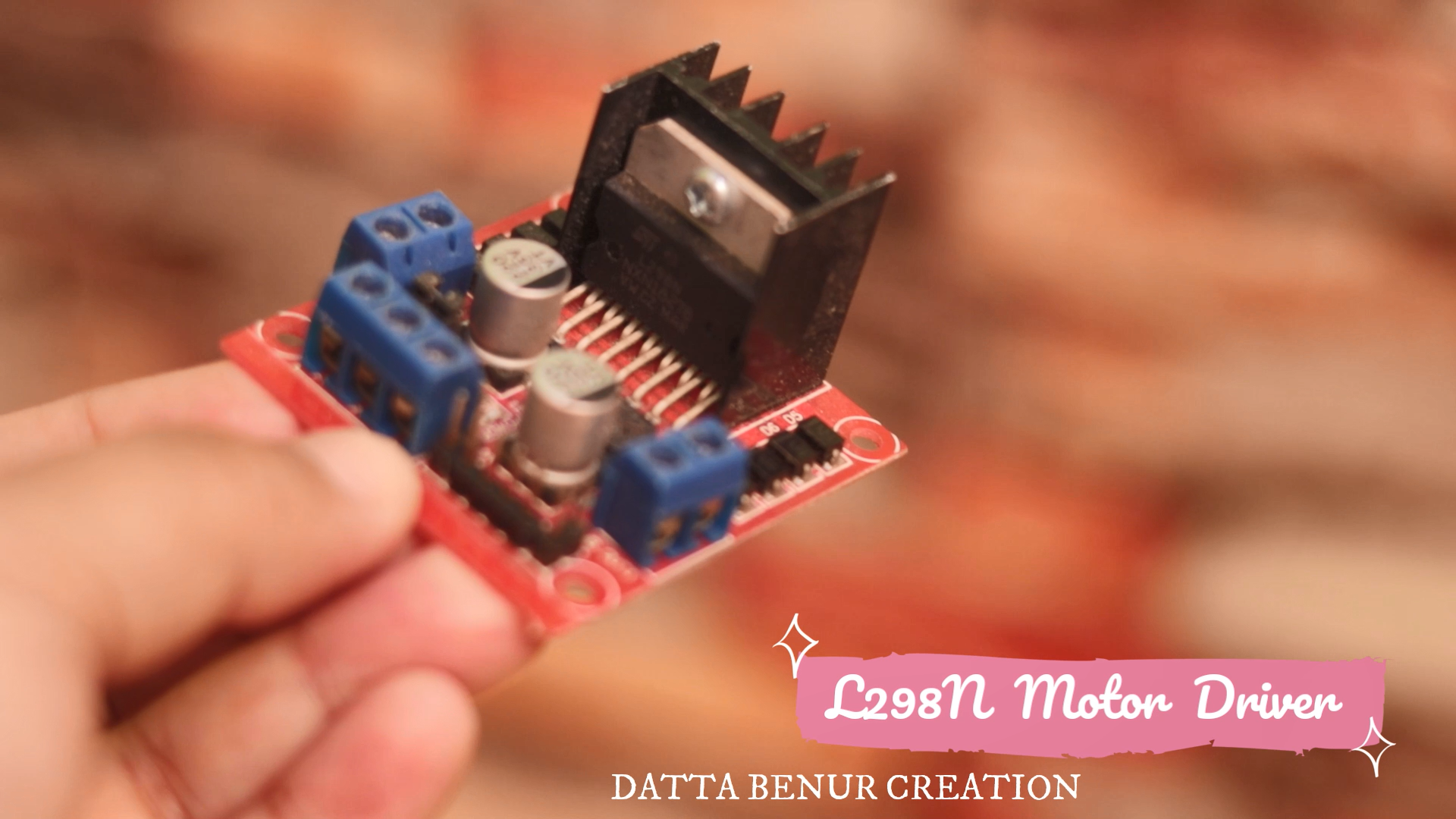
L298n Motor Driver
The L298N Motor Driver is a controller that uses an H-Bridge to easily control the direction and speed of up to 2 DC motors. The L298N is a dual H-Bridge motor driver which allows speed and direction control of two DC motors at the same time. The module can drive DC motors that have voltages between 5 and 35V, with a peak current up to 2A.
MPU6050
MPU6050 is a Micro Electro-mechanical system (MEMS), it consists of a three-axis accelerometer and a three-axis gyroscope. which means that it gives six values as output:
- three values from the accelerometer
- three from the gyroscope
It helps us to measure velocity, orientation, acceleration, displacement, and other motion-like features. It is very accurate, as it contains a 16-bits analog to digital conversion hardware for each channel. Therefore it captures the x, y, and z channels at the same time. The sensor uses the I2C-bus to interface with the Arduino. The MPU6050 can measure angular rotation using its on-chip gyroscope with four programmable full-scale ranges of ±250°/s, ±500°/s, ±1000°/s, and ±2000°/s.
_vS0GylF7v7.png?auto=compress%2Cformat&w=740&h=555&fit=max)
These were the basic details of the components that...
Read more »
 Jithin Sanal

 Miguel Wisintainer