 Sergio Ghirardelli
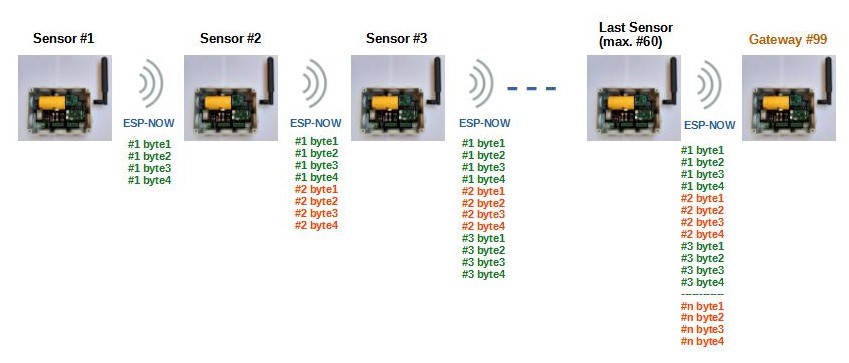
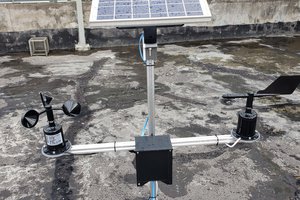
The Network
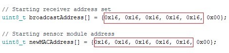
Each individual sensor module has a specific address that can be programmed by the user using the buttons on the module's electronic board.
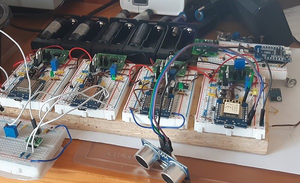
The first sensor module transmits its data via 4 bytes to the second module every 30 seconds.
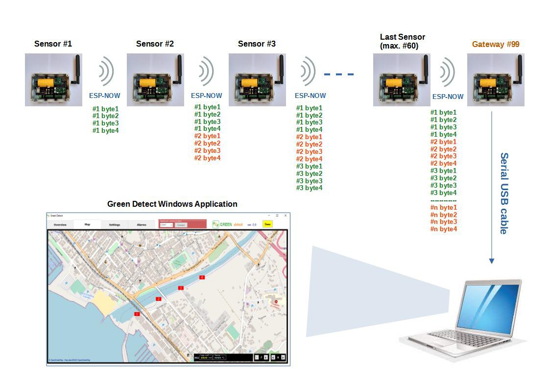
Each module receives the data
of the previous modules and retransmits them to the next module
adding its own 4 bytes.
The network can include from a minimum of 1 to a maximum of 60 sensors.
This maximum limit is to stay within the transmission limit of the ESP-NOW protocol which is 250 bytes (60x4 = 240).
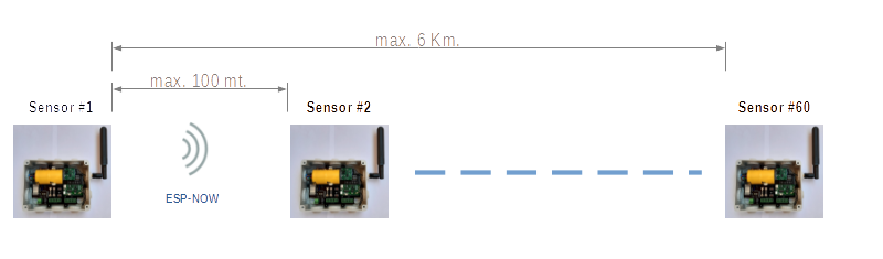
The maximum suggested distance between one sensor and the next is 100 meters
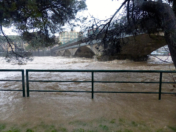
Therefore the network can develop linearly for a total length of 6 km, for example along a river.
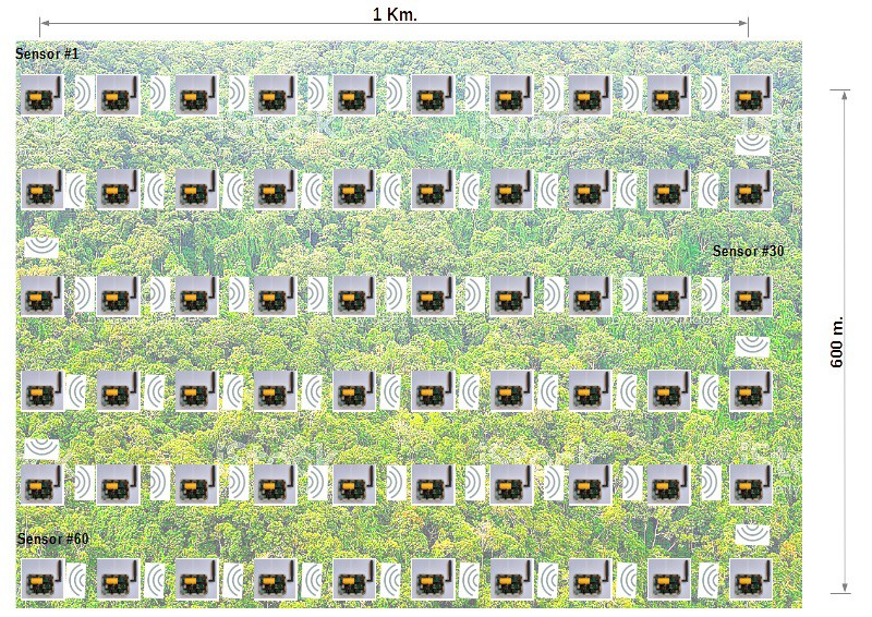
Or you can arrange the sensors in a grid covering for example an area of 1 km x 600 m, such as a field or a portion of a forest.
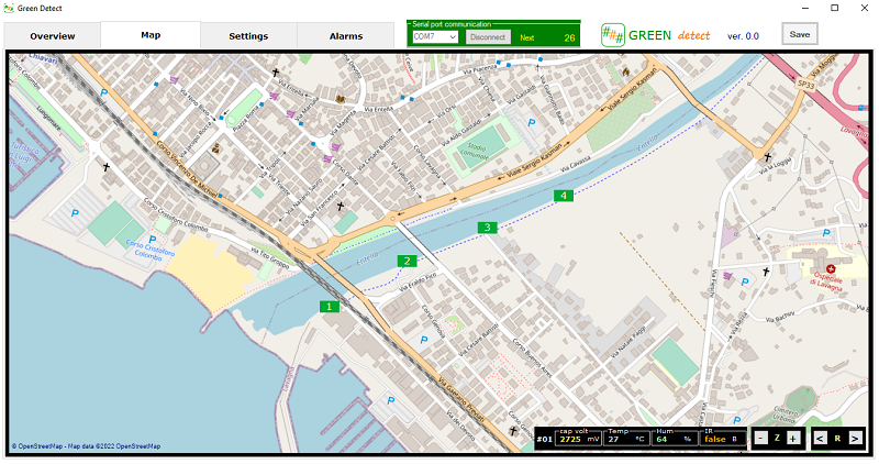
The last module of the network communicates with the gateway module connected via USB serial to the supervisor computer.
The network is completely independent from the Internet, so it can work even in remote and connectionless areas.

However, if the supervision PC is connected to the internet, the collected data can be shared in IOT applications together with the data of other Green Detect local networks, in order to create a global monitoring!
Sensor Module failure
What happens in the event of a module failure?
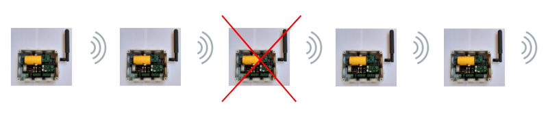
In the event of a module failure, communication is interrupted and the acquisition of all sensors is momentarily lost.
After a delay time of 2 minutes, the module following the faulty one begins to transmit data to the following modules, informing the supervisory system of the fault to the previous module.

This condition generates a specific alarm and it is therefore possible to go promptly to replace or repair the faulty module and restore the network in a very short time.
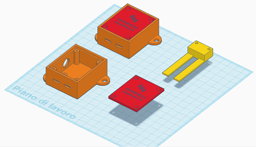
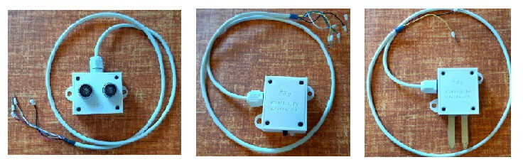
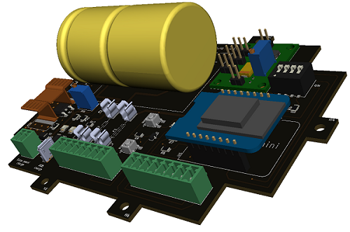
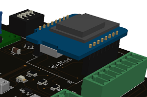
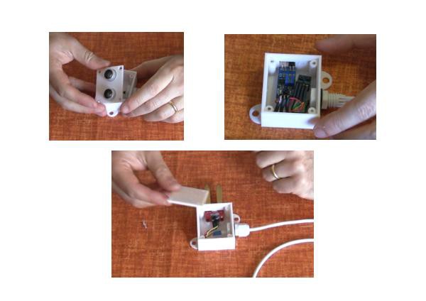
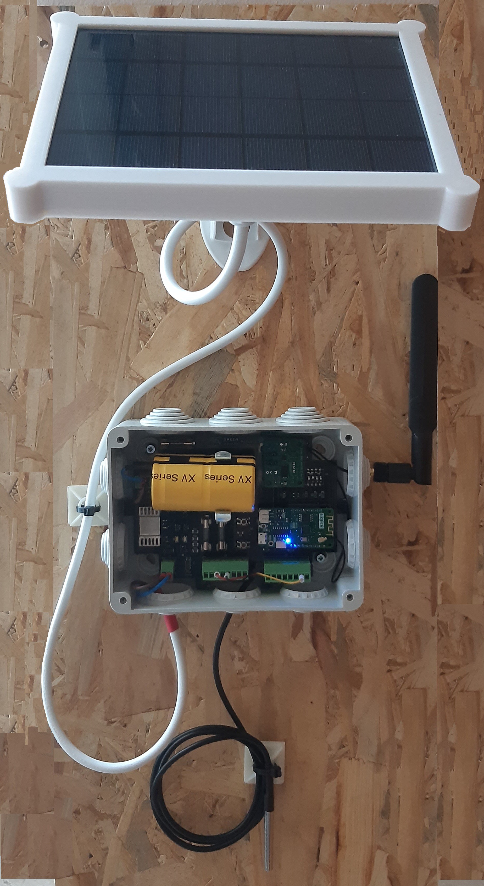
Sensor Module description

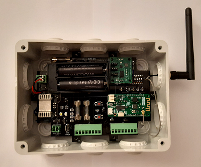
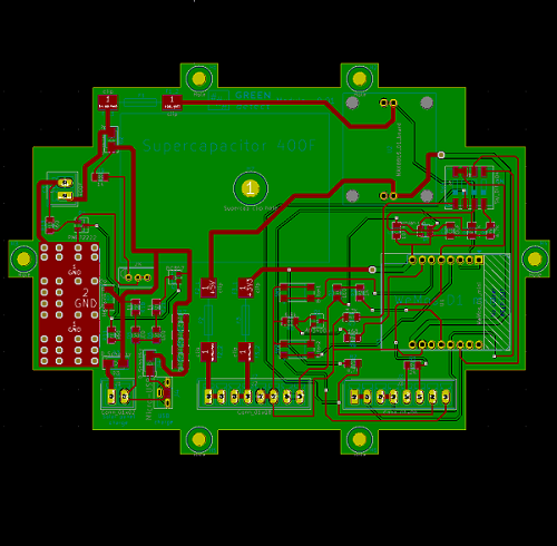
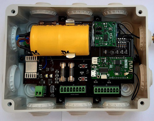
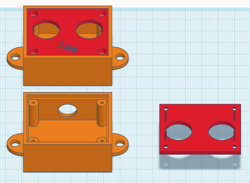
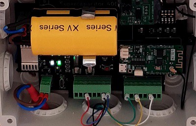
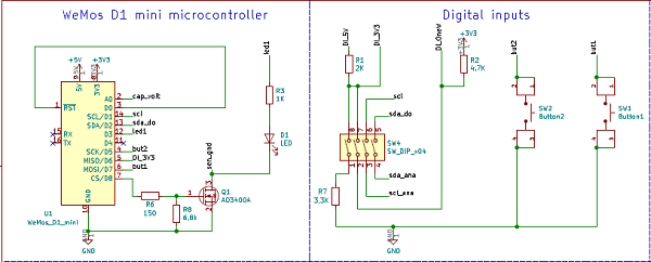
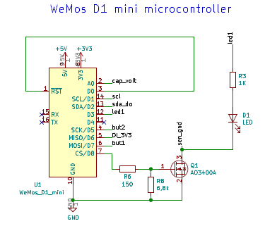
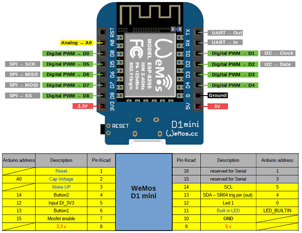
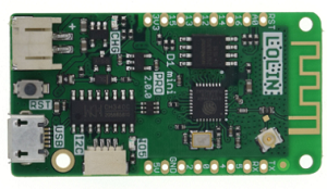
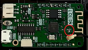
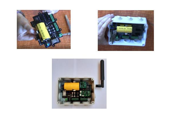
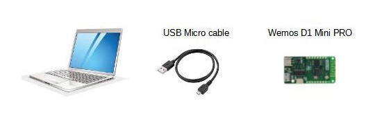
The sensor module is based on the Wemos Mini PRO board, containing the ESP8266 microcontroller.
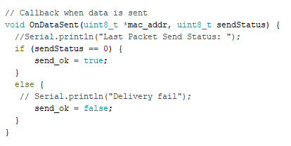
The Microcontroller programming software was developed with Arduino IDE.
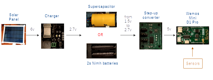
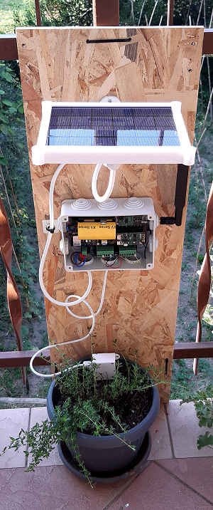
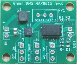
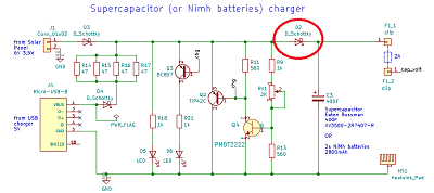
The power supply to the microcontroller and the sensors connected to it is provided by a 400F supercapacitor, whose output between 1.5v and 2.7v is raised to 5V by a step-up converter.
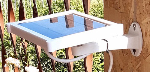
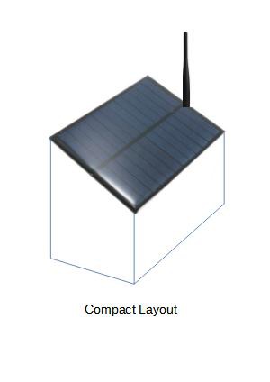
The supercapacitor is charged during the day by a 6v 3.5W solar panel.
The supercapacitor is not soldered to the board, but is fixed by a clip and connected by a connector, in order to make its possible replacement quick and easy.
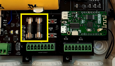
In critical geographic areas (low light, rainy areas) or in case of high consumption sensors, where the supercapacitor may not be able to meet the energy needs, it can be replaced with 2 Nimh batteries in series, without modifying the board, just plug into the same connector.
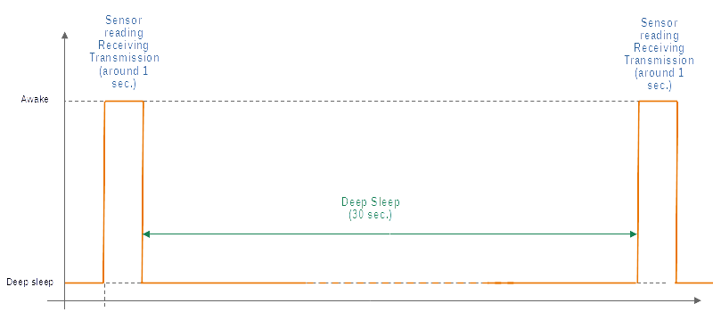
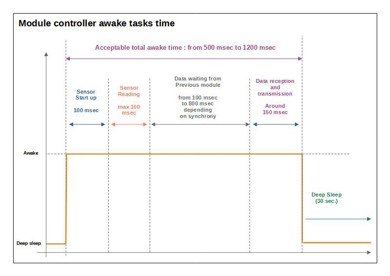
The module works according to the following steps:
1. sensor signal acquisition
2. receiving data from the previous form
3. data transmission to the next module
4. Deep sleep mode (30 seconds)
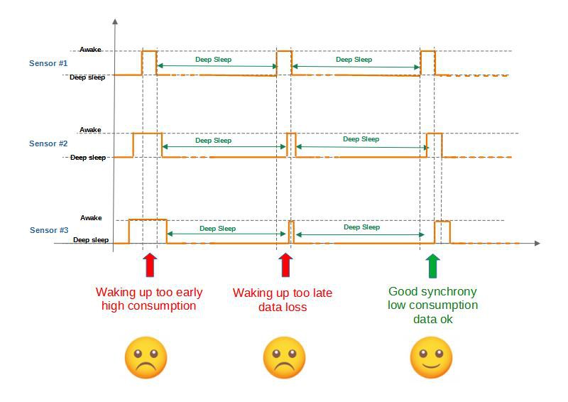
All modules connected to the network are synchronized with each other.
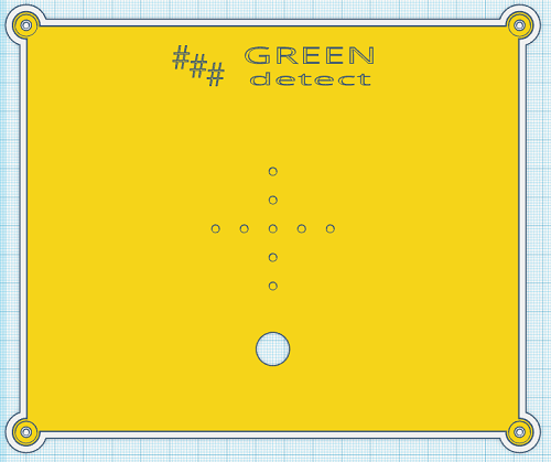
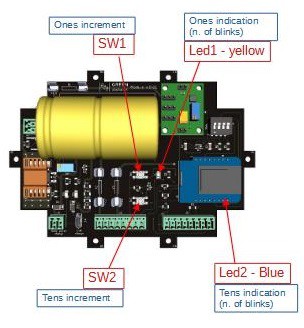
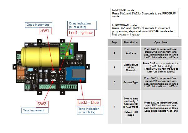
Using the buttons and leds on the board, it is possible to program the module by defining the address and the type of sensor used.
The settings are stored in the flash memory of the microcontroller.
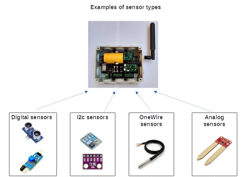
The Sensors
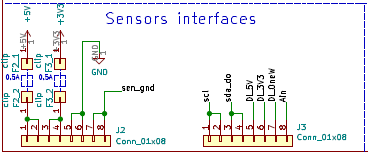
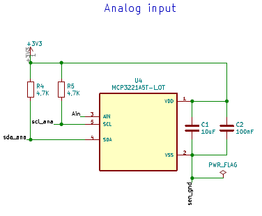
The module can accept digital, analog (10 bit), Onewire and I2C sensors.
Two or more sensors can be combined and connected to the same module, the limit is represented by the fact that we can transmit a maximum of 3 bytes.

Each type of sensor (single or combined) is associated with a unique number, up to a maximum of 99 sensor types.
The addition of new sensors involves updating both the microcontroller software and the supervision application: everyone can do it because the project is Opensource!
If you set sensor type = 0, the module is used just as repeater.
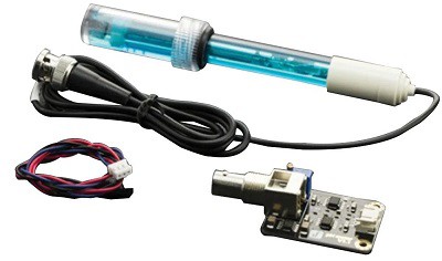
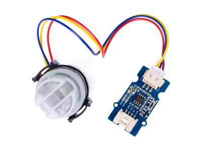
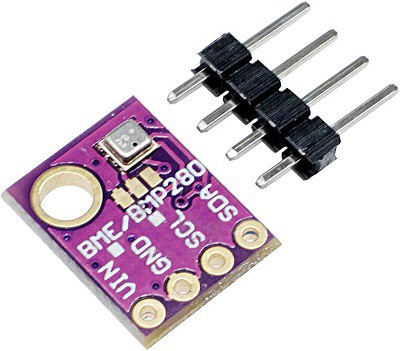
Here are some examples of sensors that can be connected:...
Read more »


 Makerfabs
 Danie Conradie
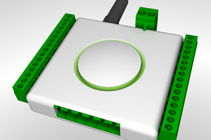
 Laurence
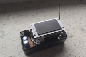
Hello. I'm interested in your project.
I want to ask, why you attach Lolin D1 Pro in components section, when you use Lolin D1 mini while prototyping?