 Matt
MattProject background and parameters
This project addresses the challenge of how to re-use old instrumentation and defunct PCB's in a way that doesn't match their originally intented purpose. My job involves designing lab instrumentation, specifically for electrochemistry, which uses a decent amount of analog circuitry. Our products are sort of like fancy 4-quadrant power supplies/loads, with signal generation and frequency response analysis. Designing these products has been a wild, on-the-fly educational journey, including the many (many) times I've learned the hard way about hardware vulnerabilities and design shortcomings that I did not anticipate. As a result, over the years, we have accumulated lots of junk boards, which we draw upon for spare parts. These have damaged components, burnt up traces, and design configurations that just didn't meet our intended specifications.
I wanted to make my parents a Christmas present that would show off audio recordings of my daughter that I have accumulated over the years. I thought my daughter and I could decorate a gramaphone or record player as a cute way to house an audio player pre-loaded with these recordings. Since I also wanted to decorate the vinyl record, putting the project on a working custom vinyl record was not an option. I shopped around for antique gramaphones before finding an inexpensive record player from a thrift store, complete with a record from a band I hadn't heard of (something like "The Beetle Boys", I don't remember, it's covered up now with glue, paper, and stickers).
After thinking through how to cheaply and quickly construct an audio player, I realized that our instrumentation has a lot of the components I needed: an amplifier stage that can apply 1 Amp of current from DC to 1MHz; a 16-bit DAC; a microcontroller and a programming header; and a slot for an SD card (originally for data logging), with SPI connections to the microcontroller.
Meanwhile, the record player lacked a built-in speaker, and only had an audio line out. So besides the motor that spun the turntable, the on/off pushbutton, and the AC power plug/cord, there were no useful electronic components on the record player. I also needed to mechanically disable the needle arm so that it wouldn't catch on the bulky foam and glitter paper we glued to the record surface. I removed as many of the unused internals as I could to make room for my own reclaimed components/PCB fragments.
Instead of just removing individual components from my junk boards, there were enough useful PCB connections that it was worth cutting out small portions of them and completing the rest of the connections with board-to-board wiring. Here is what I was able to excise:
- PCB fragment 1: PIC32 microcontroller + microSD slot + 16-bit DAC
- PCB fragments 2 and 3: Voltage buffers + class AB amplifier stages
I used one buffer/amplifier to drive the audio signal coming from the DAC, and the other to hold a stable mid-scale voltage for the speaker return path, since I was using a single supply voltage. (A simpler approach would have been connecting one end of the speaker to ground through a large capacitor. However, early in the project, I didn't know what speaker impedance I would be dealing with, and harvesting a second amplifier stage allowed me to not worry about filtering out too much bass if I didn't pick a big enough capacitor.)
Here are other components I harvested elsewhere:
- 3.3v linear regulator (mounted on a perfboard)
- 12VDC switching power supply
- Speaker from radio alarm clock
- 16GByte MicroSD card
I've included a Github link and KiCAD schematics (the schematics are also duplicated in the Github repository). I didn't include layout files, since these are scraps from proprietary products. The code is fairly straightforward: the microcontroller reads from the SD card via SPI, using an open-source library for FAT32 file systems. The raw audio data from the .wav files are clocked out to the external...
Read more »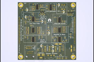
 Jan B.
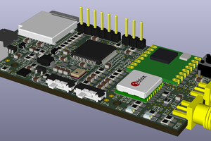
 Fabien-Chouteau