 Kevin Santo Cappuccio
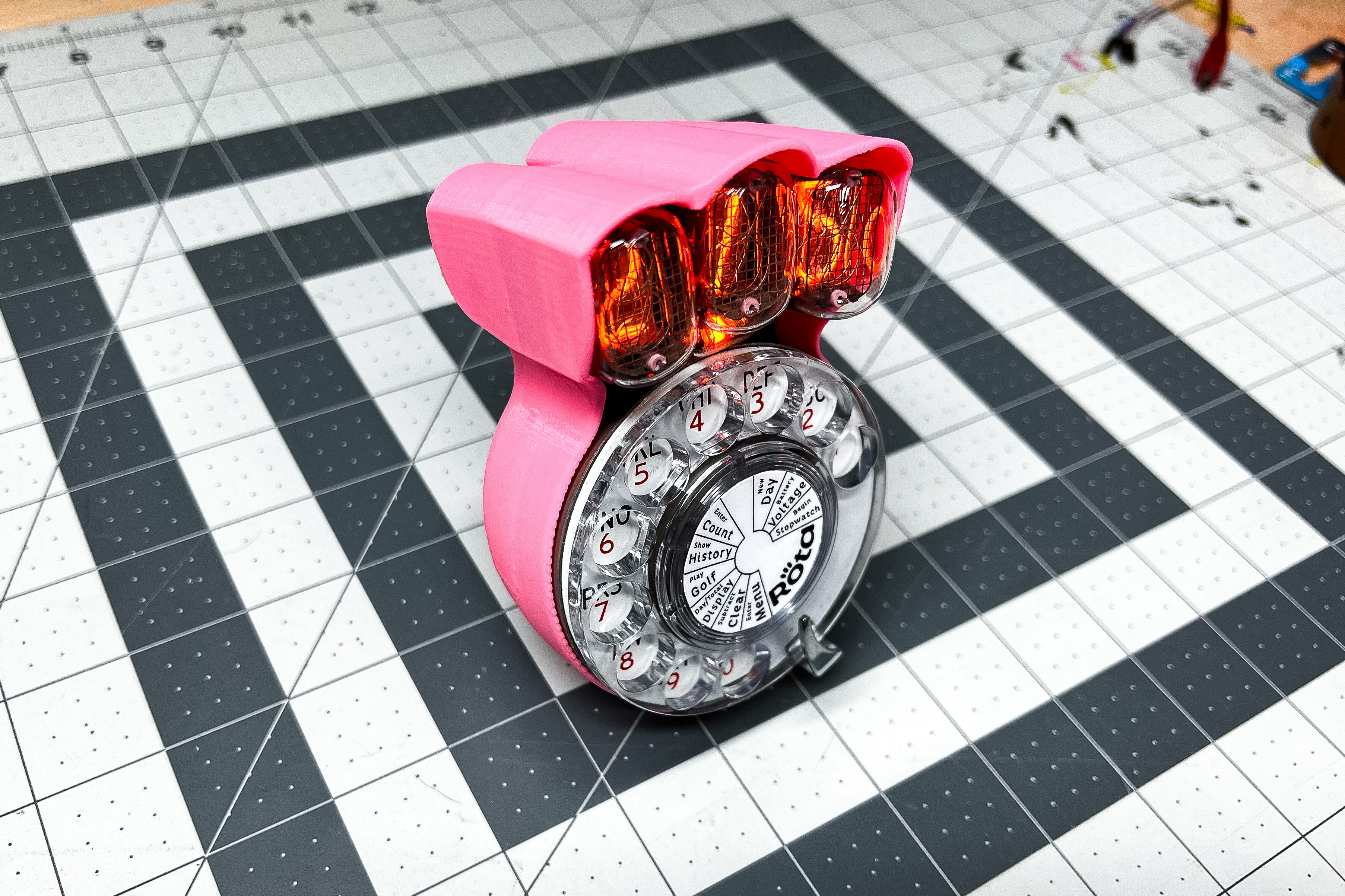
This is the more complete version of Rǒta
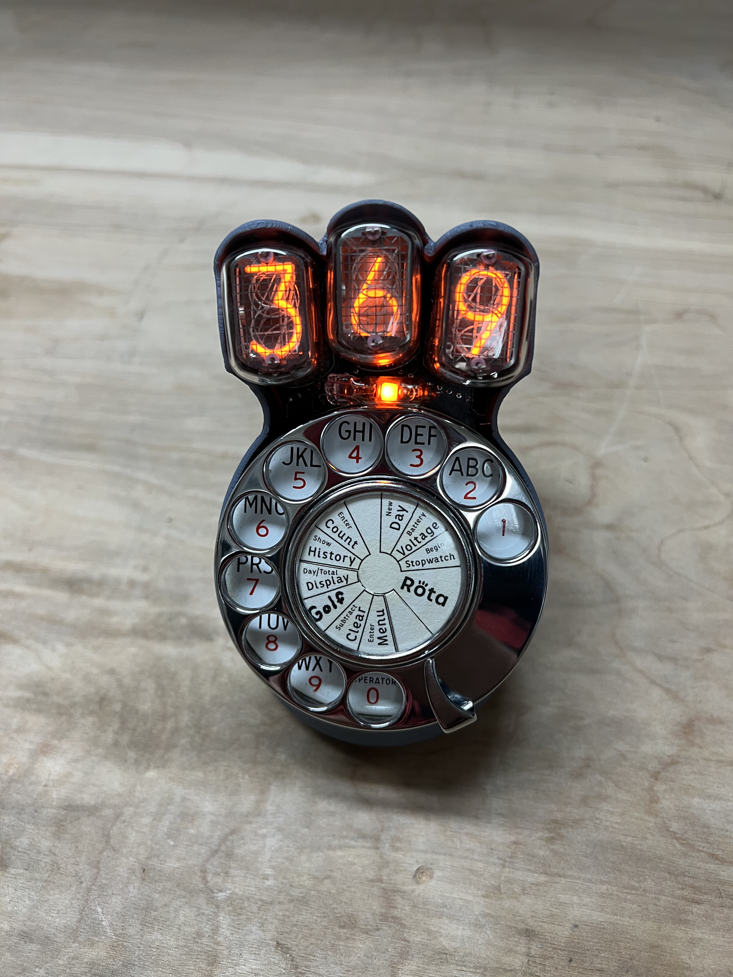
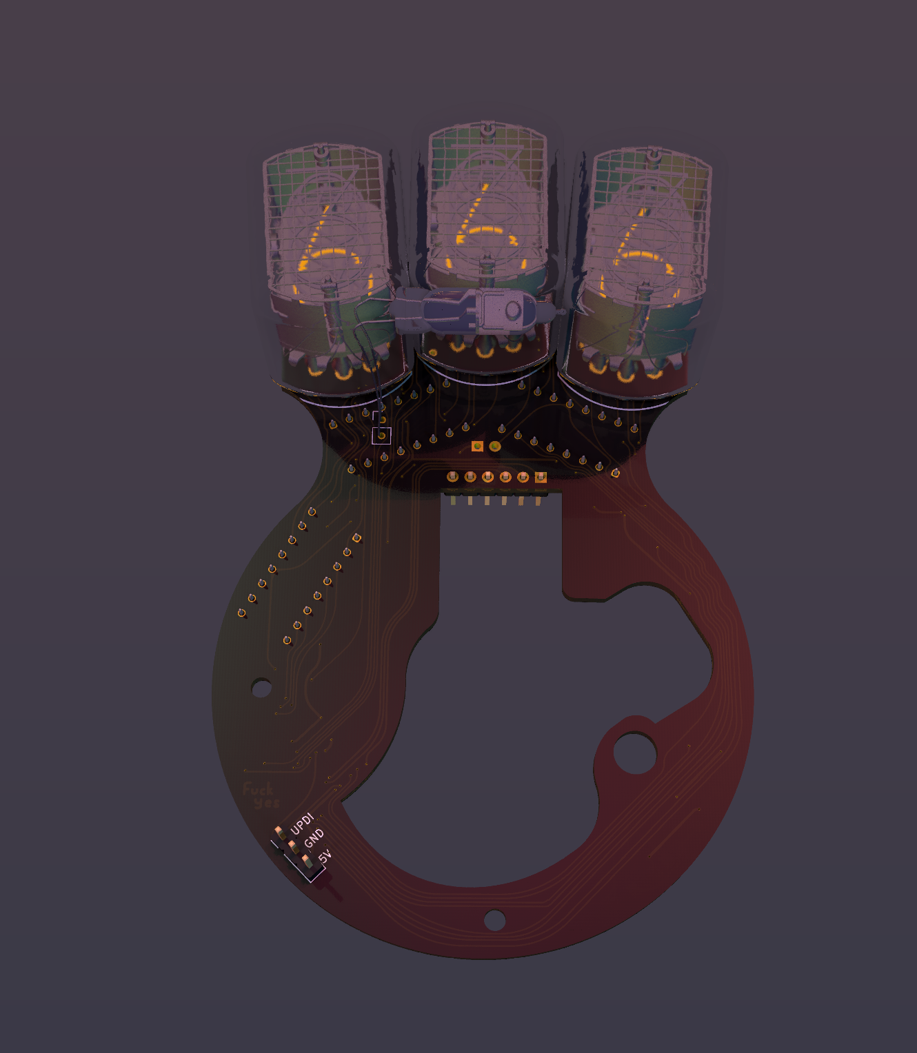
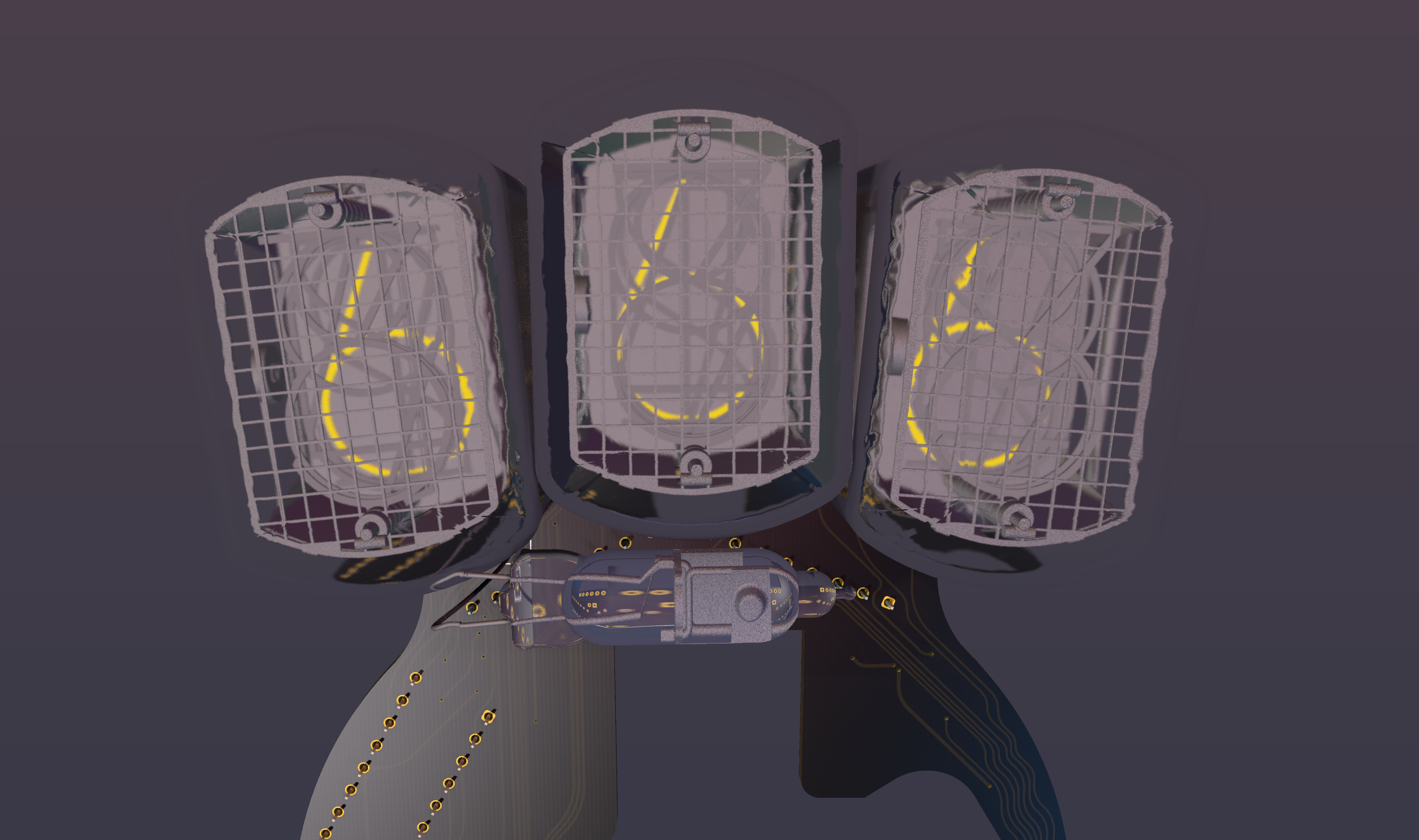
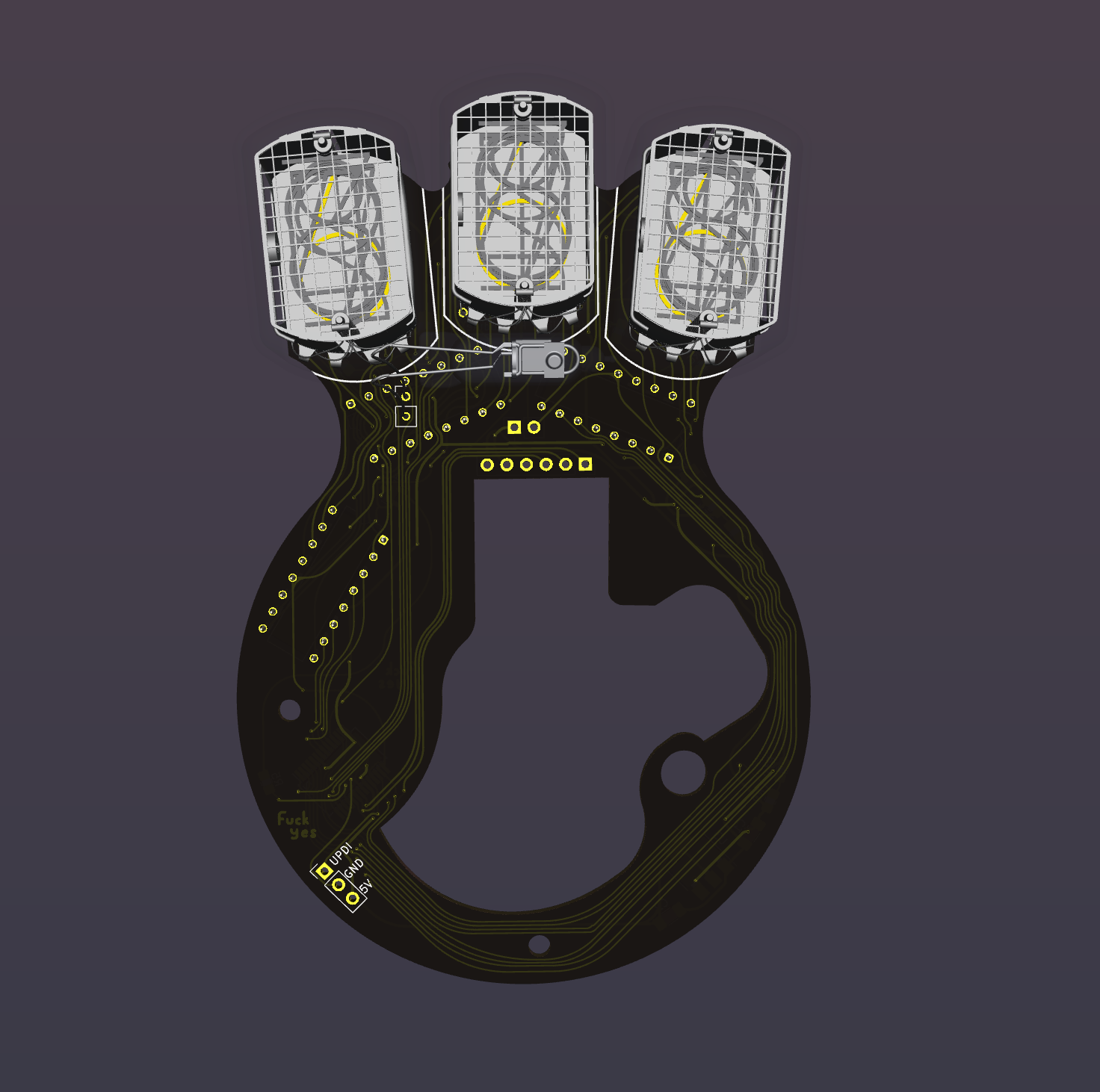
That flashing means it wants your input. These decimal points do way more work than regular decimal points, they tell you a lot about what's going on. When you don't have segments to make crude letters and stuff, you need to get creative with dots.
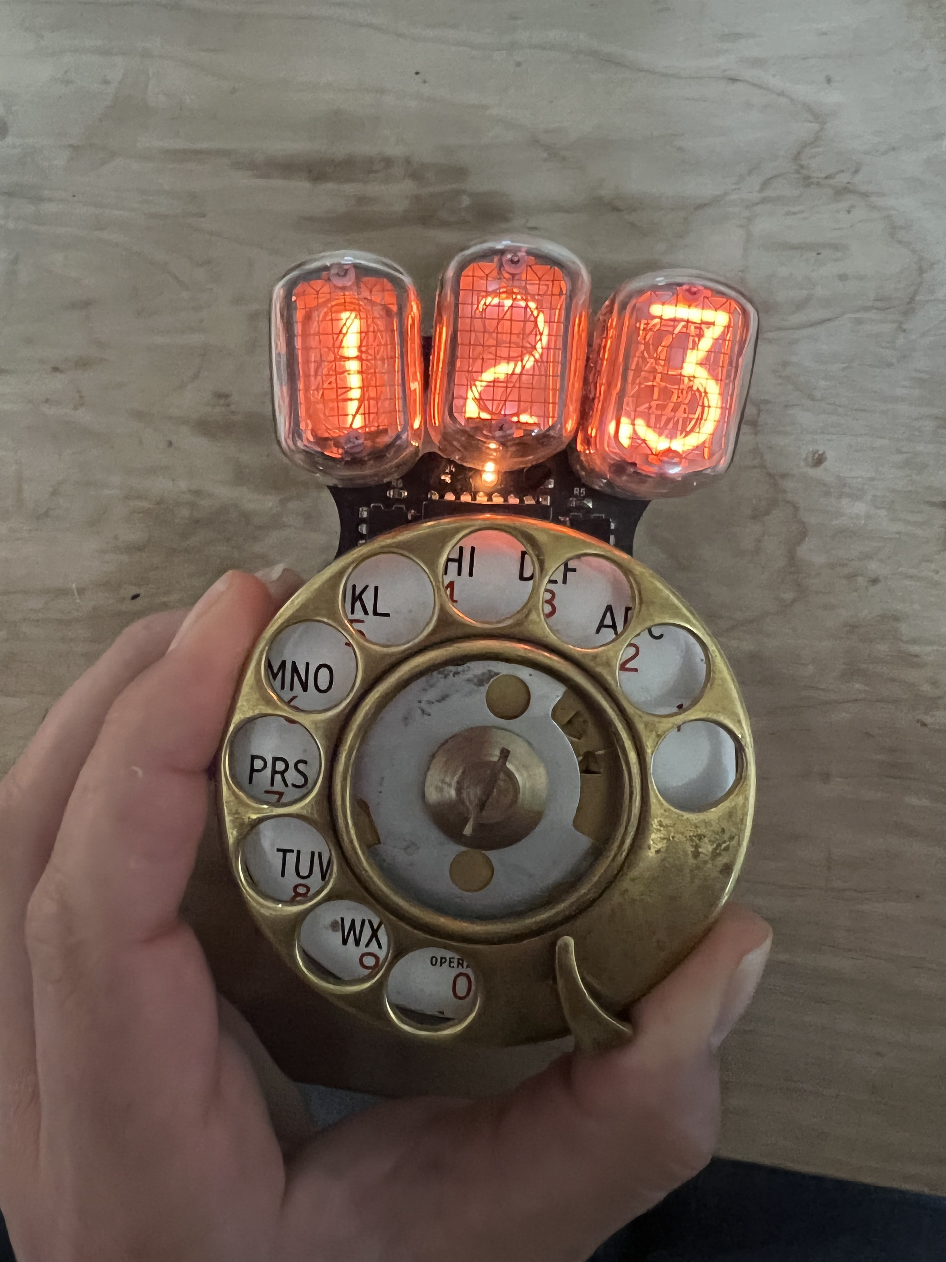
It was originally conceived as a gift for a duck hunting lodge, but now I'm making a few more and I know not everyone is into hunting so it's been generalized into a tool for just counting stuff in general where those $3 hand clickers or a golf pencil just lacks the glamour you need in your life.
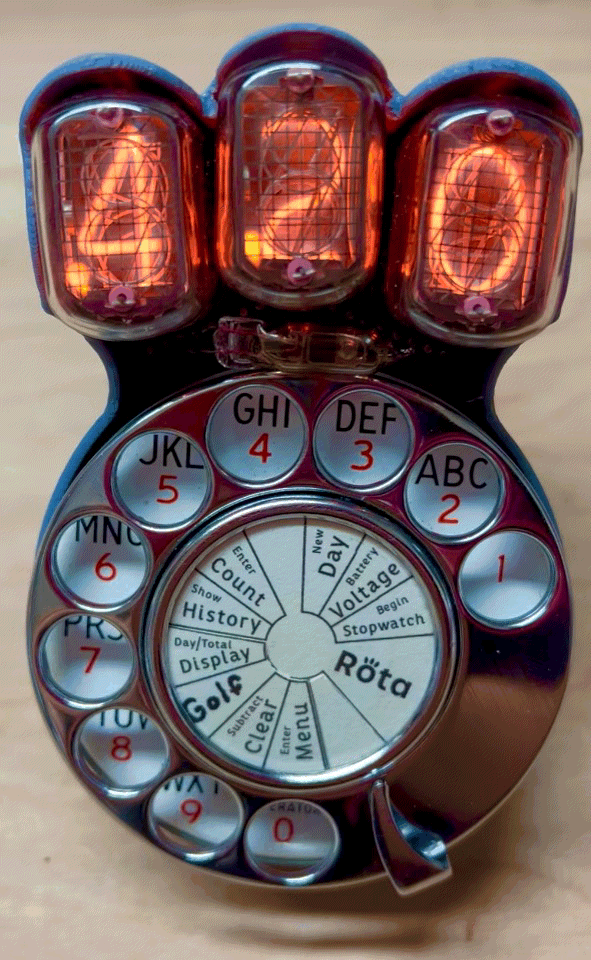
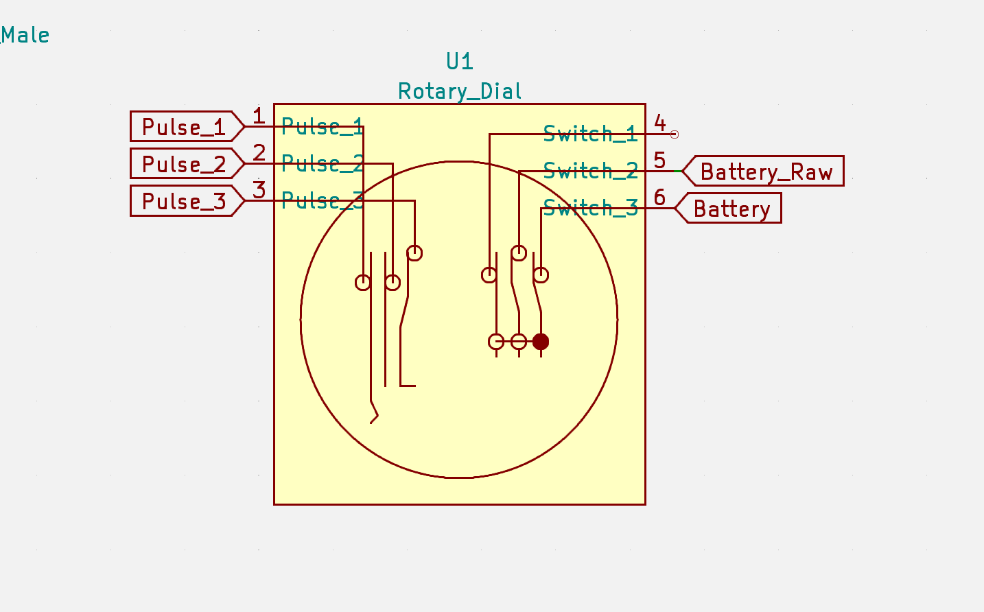
Instead of using sequences of numbers to use the special functions, now you just dial 0 and then the function you want which is printed on the number plate.
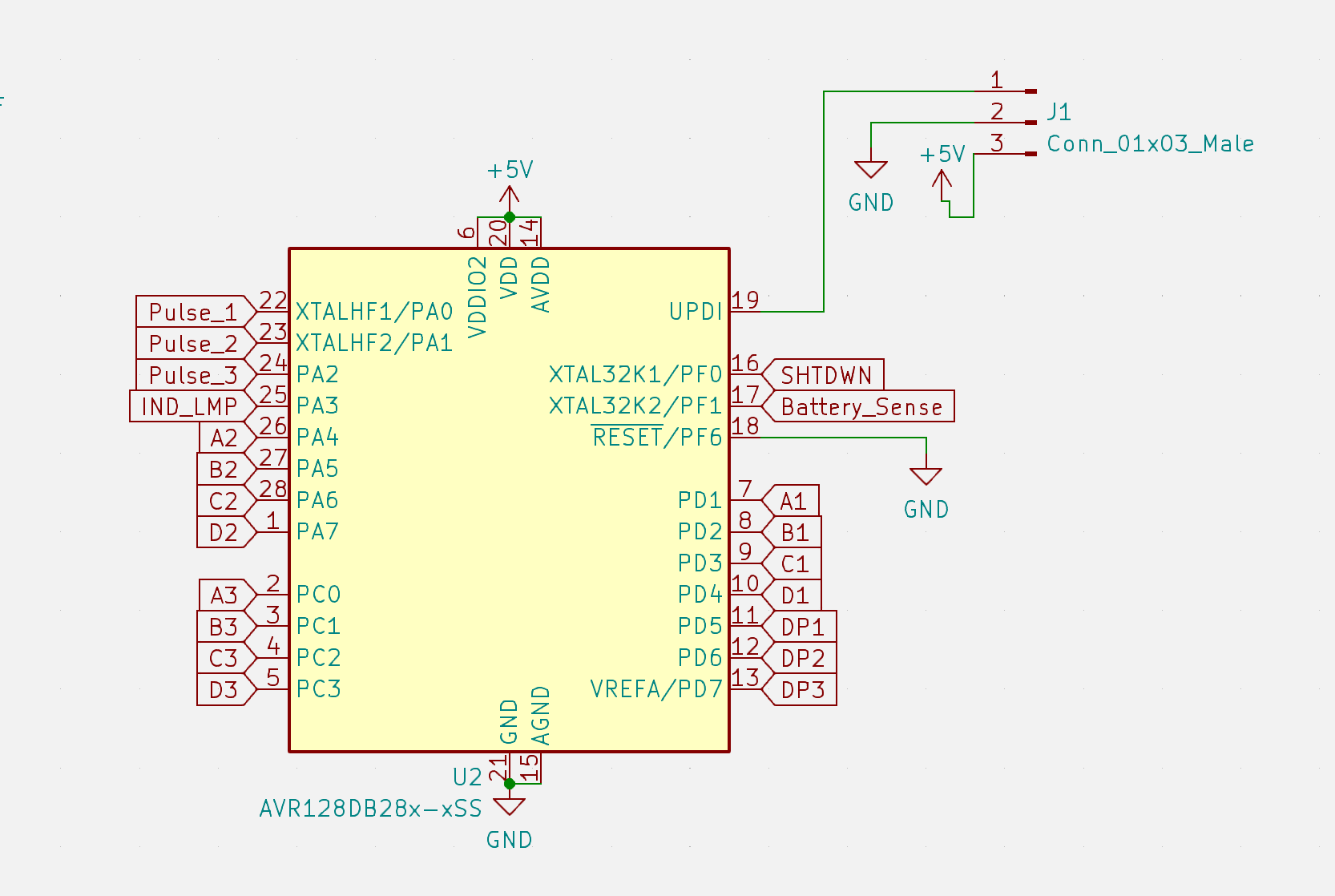
here's the special function menu map

note - I'm calling moving the dial just a little to turn the display on a "click"
when inside a special function, dial anything to exit (preferably 0 because it's only reading intermittently when in menus, so it's most likely to register)

0 -- enter/exit menu or function   shows 111 when you're in the menu)
1 -- stopwatch                    click to start, click again to see last time.
2 -- show battery voltage         briefly turns off the display to get a more accurate reading (not under load)
3 -- new day                      this stores the total since the last time you started a new day. maximum 63 days
4 -- does nothing
5 -- enter a count by digits      enter 3 digits (hundreds - tens - ones) to add to your daily total
6 -- show history                 click through each day with first the day number (on the left) then the total for that day
7 -- toggle day/total display     either shows the count for that day or the running total of all days (default is total)
8 -- golf mode                    keep score for golf - first enter 1-4 players and the decimal points show which player's turn it is
9 -- clear everything             dial 9 again to confirm. dial anything else to go back
999999 -- emergency clear         dial 9 six times to emergency clear everything in case something gets messed up same as dialing 10 9 9
                                  you can also short the middle pulse pin high for super duper emergency clear
If you want to see what these modes look like, here are some videos of me using them,
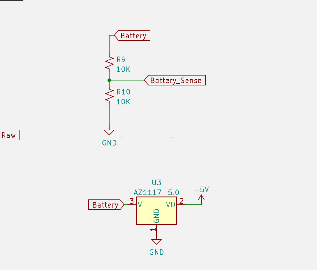
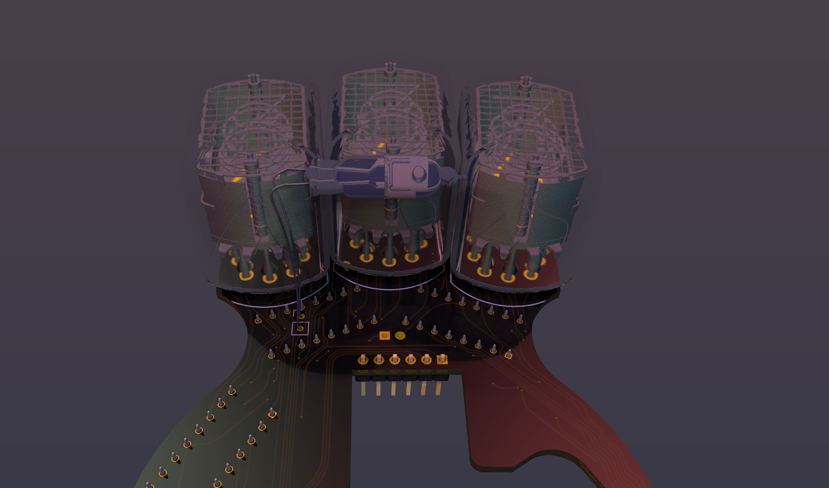
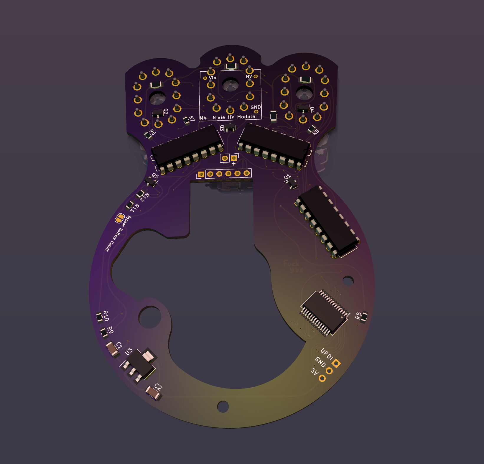
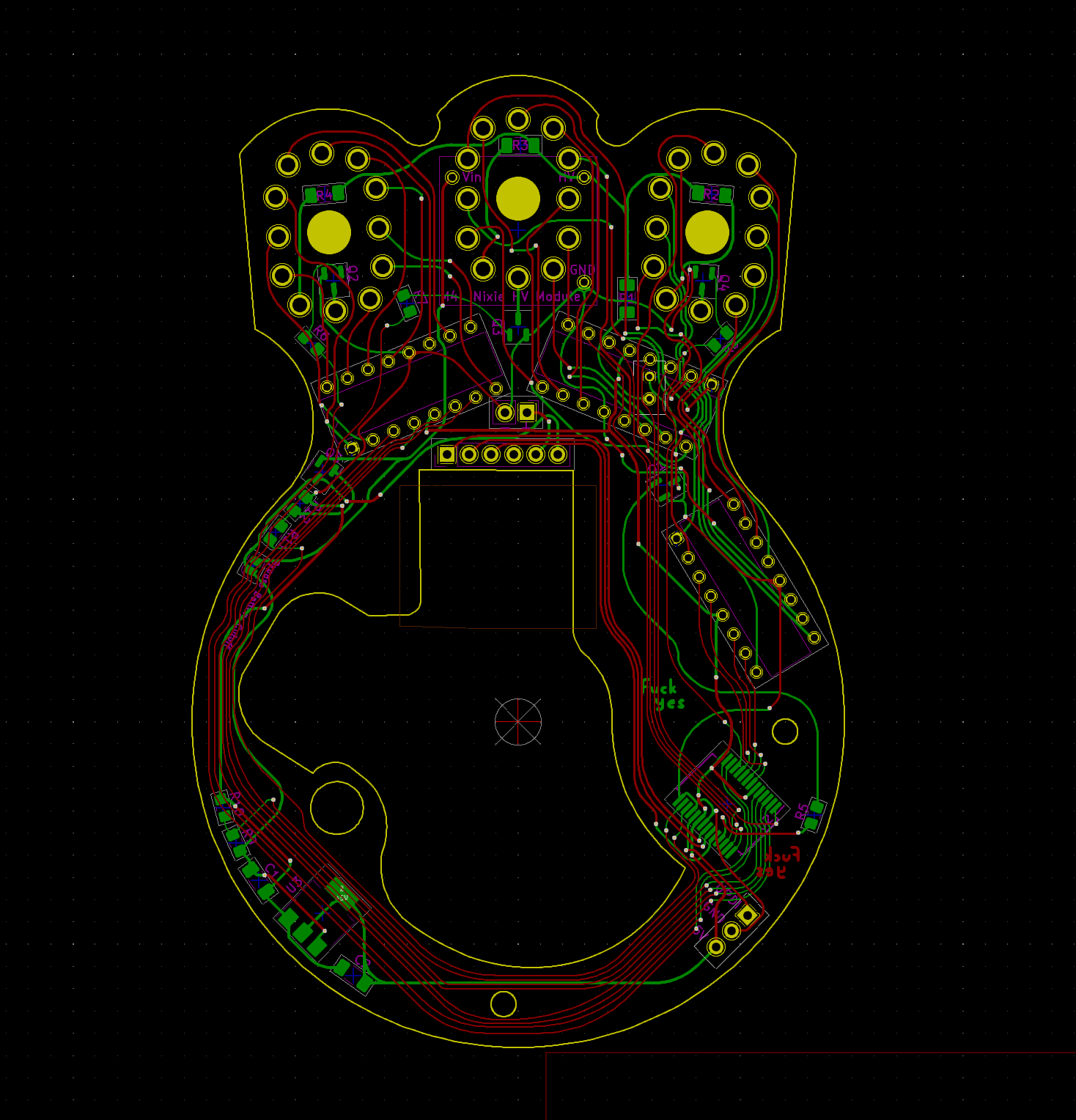
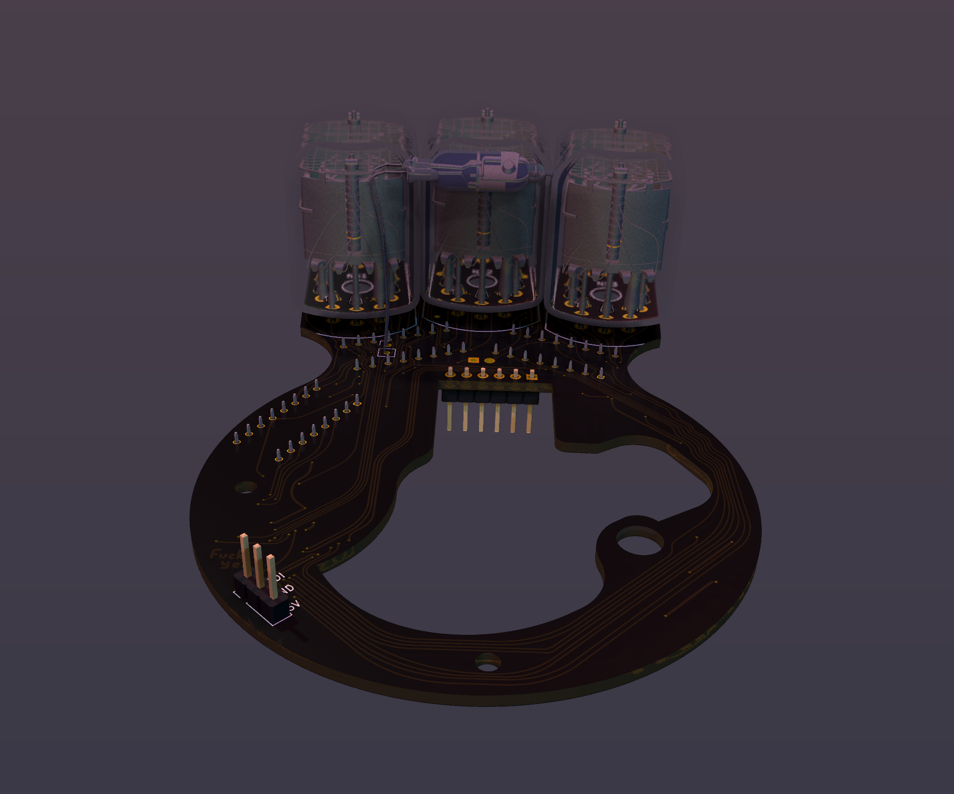
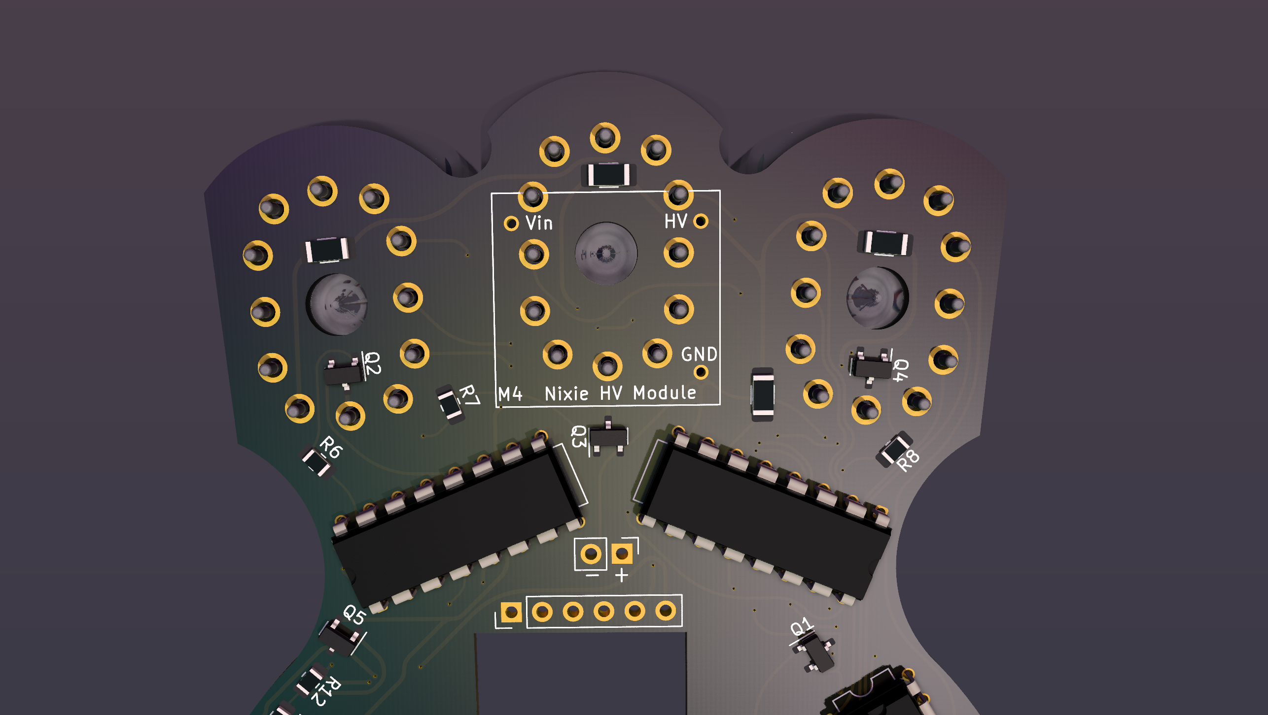
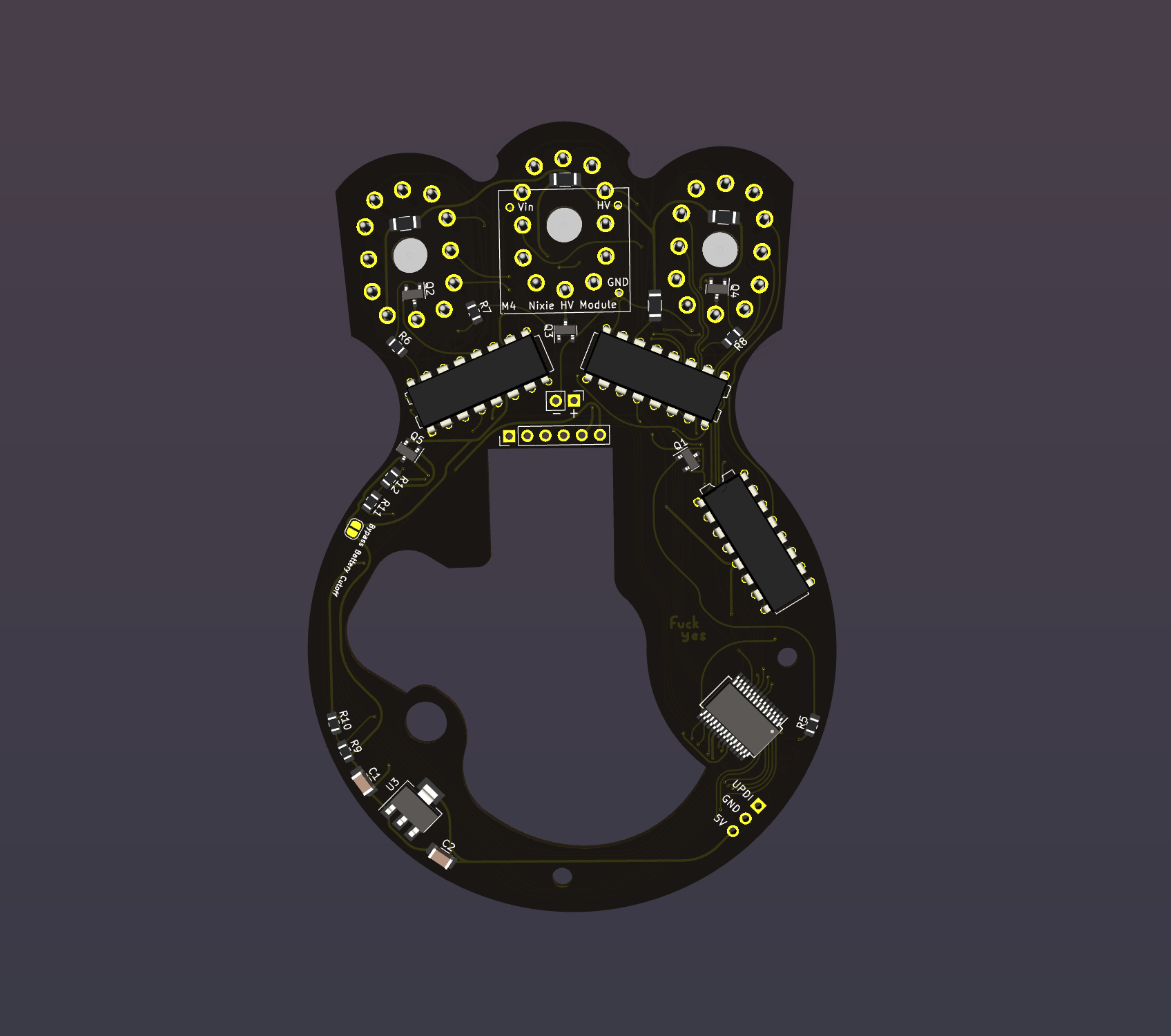
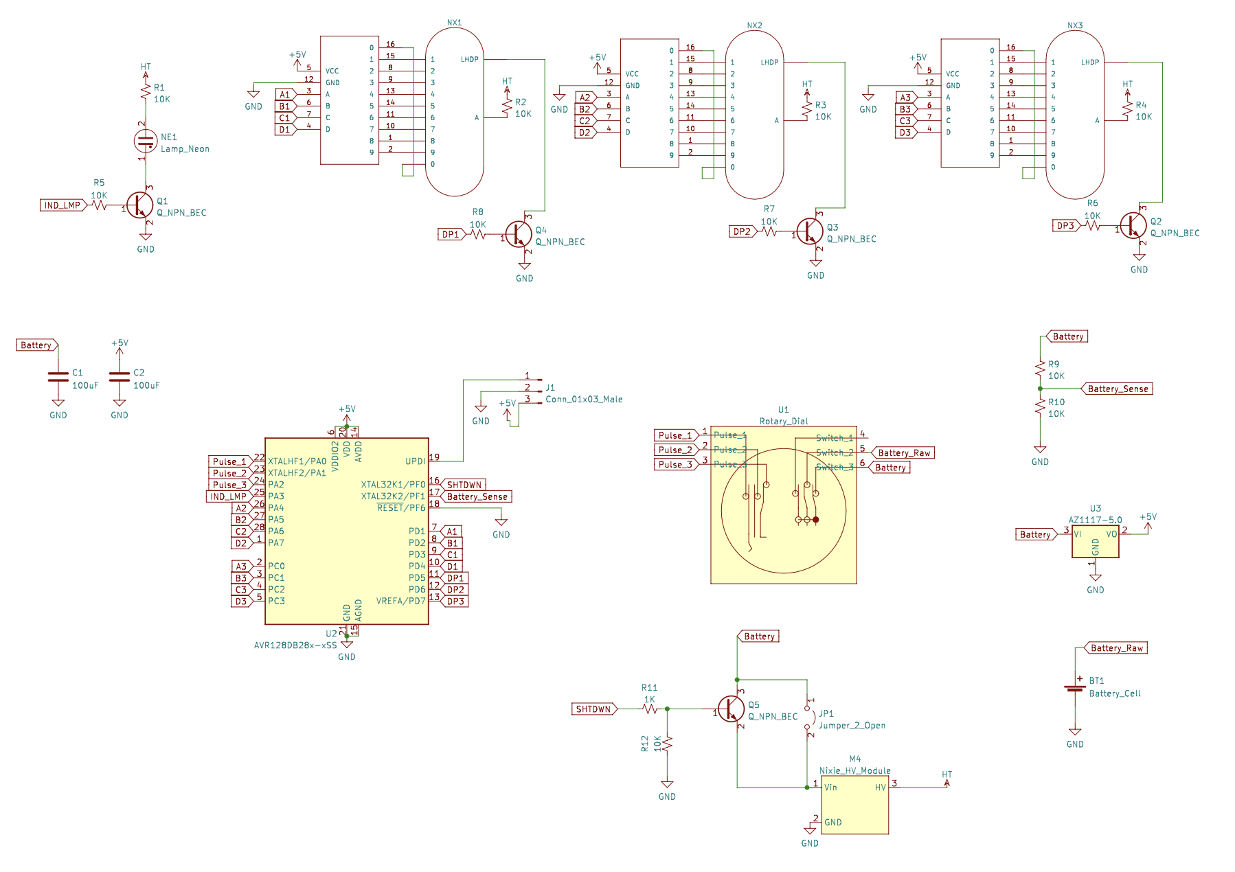
The voltage display was added because I was having issues with the K155ID1s browning out before the HV module (it still blows my mind that it works down to like 3V), so the display would just show all the digits on because the nixie drivers weren't blocking any current.
The previous 1-transistor version of this was a silly mistake, here it is fixed.
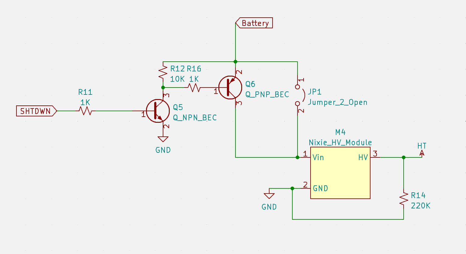
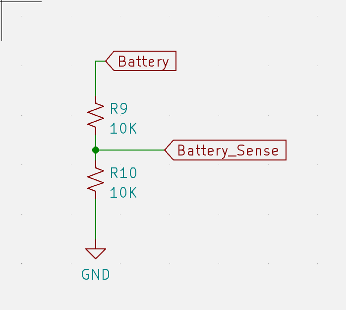
Now if the battery voltage is too low, it shuts down the display but still takes input. In case you don't have a spare battery but still want to count. And the power draw is so low for just the microcontroller that the battery life might as well be infinite.
If you notice in the video, the display flashes when the battery voltage updates, that's because when it does the measurement, it briefly shuts the HV module down so we can measure the battery voltage unloaded. Because this thing draws ~300-400mA when it's on so without doing a ton of math and testing different 9v batteries to correct for it, the voltage it shows would be like ~2V lower than it really is unloaded.
... Read more »


 ipaq3115
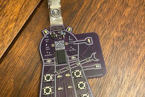
 Jorj Bauer
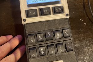
 John Duffy
 Jean Simonet
Version 2 looks Fantastic ! And I love the fact you took the time to enhance it. I have already ordered a couple of dials. I'll wait on the PCB BOM until you validate it!I am absolutely going to build this as I'm always looking for nixie projects that are not just another clock. I have too many of those already :-) Again, thanks for posting this project. What board house did you use? I typically go to JLCPCB or seeedstudio.