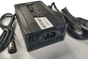
Specifications (as pictured):
- Power: 12V LA (Lead Acid) or LFP (Lithium Iron Phosphate) battery. Recommended minimum capacity 3.8Ah (dependent on pump/load & desired run-time).
- PV panel: 10W, 12V or similar. MPP voltage ~ 17V. Open circuit voltage should not exceed 24V.
- PV charger efficiency: 93%.
- PV charger type: pulse.
- Charging cut-off: 13.8V.
- Pump / load: 12V DC (nominal), 3.4A max continuous.
- Pump drive circuit efficiency: 94%.
- Pump type: centrifugal, 800LPH max each.
- Protections:
- Battery Under Volt Lockout (10V).
- Pump Over-Current Lockout (3.4A).
- Battery fuse (5A).
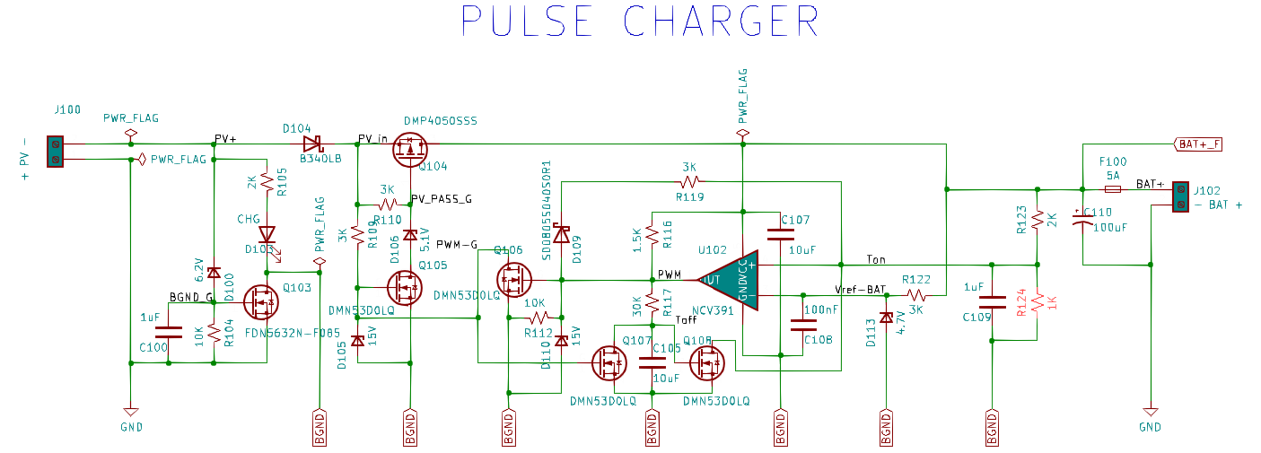
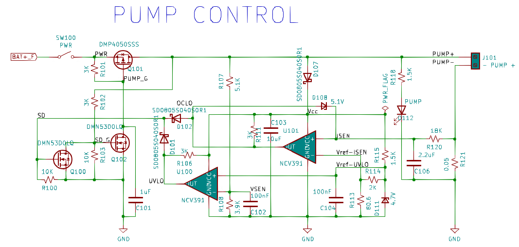
The core of this project is the PV charger & pump control board. It is designed to be cheap (most of the cost is external: pumps, PV, plumbing, etc.), rugged, and easy to build. Also flexible: it is shown here powering a set of [cheap] high-volume pumps widely available on eBay but can be used with any compatible load - an off-grid charger for electronics gear, a cooling fan, etc. The pump control circuit can also be scaled up to handle higher power levels, say, 100W.
Moving up the complexity scale, a microcontroller could supplant the pump control section to provide scheduling functions like watering garden beds, transferring water to a cistern, etc. Load current could also be intelligently monitored to stop running when the barrel runs dry.
You can find the KiCad v5 project here if you'd like to work with it. Note that if you opt to use an LFP battery I recommend NOT using one with a BMS (Battery Management System) since this circuit provides the basic protections.

 David Brown
 George
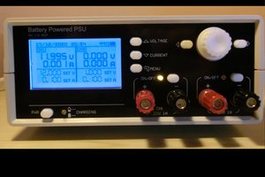
 Manuel Tosone
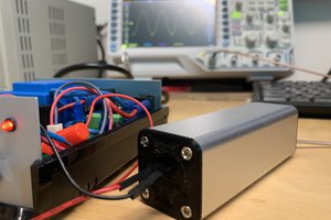
Hello, I started looking into having jlcpcb.com create a circuit board but a few parts they didn't have in their library. Do you have any suggestions as to a place to get the board made that you utilized that has the parts in their library? For reference these are the parts that weren't being found.
D106,D108
D100
F100
D112
D101,D102
D111,D113
U100,U101,