 kaimac
A lot of the hardware design is done now and I've sent a couple of PCBs off, so I can document the various bits. Here's the ALU:
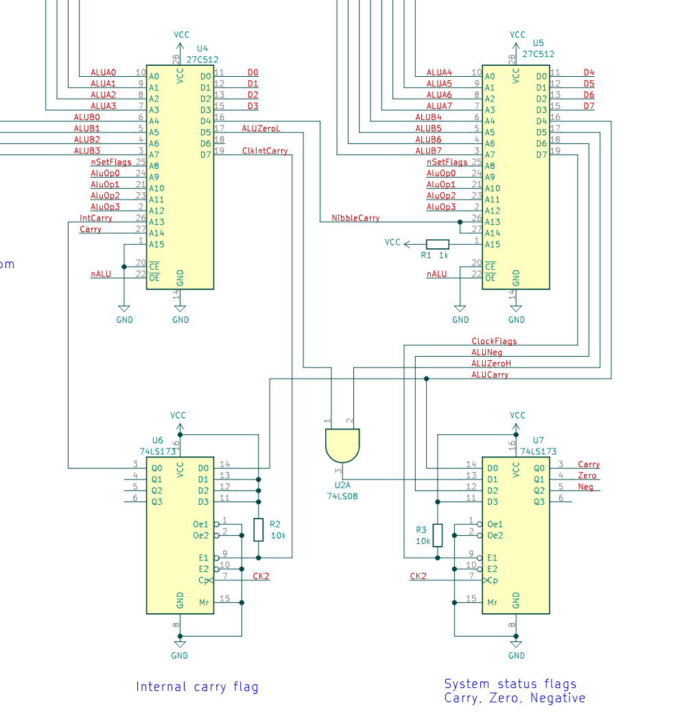
There are two 64K x 8 EEPROMs, each generating 4 bits of the result. Both ROMs use the same image, but A15 is pulled low on one and high on the other, so they can behave slightly differently. The "A" operand comes from the register file and the "B" operand is hardwired to a temporary register called T. To do x=x+y, y is first moved to t, and then "add x, t" will add t to x.
There are 16 possible operations, set with the four AluOp bits:
- 2x pass-through operations, Q=A and Q=B. Needed to store a register into memory for example, as the only way to read a register is through the ALU. Q=B is used by some instructions that use the T register as a temporary location. For example the "stl" instruction (store literal to memory) first writes the literal value to T, and then writes it back to memory.
- 6x arithmetic: add, sub, adc, sbc, inc, dec. These are exposed in the instruction set.
- 3x logic: and, or, xor. These are also available as instructions.
- 2x conditional increment: ci increments if the carry is set, and cd decrements if the carry is clear. These are used by the microcode to (for example) add an 8-bit offset to a 16-bit address.
- 2x operations (ror1 and ror2) that together perform a rotation right by one bit - explained below!
- 1x operation (sig) that makes the next comparison signed - also explained below!
These are all defined in a Python script that generates the ROM image.
Flags
The three status flags come out of the ALU and are stored in a register. The high ROM outputs the final carry and the negative/sign flag, which is equal to bit 7 of the output. The zero flag is the zero output of both ROMs, ANDed together.
There is another, hidden, "internal" carry flag, stored in U6. This is used by instructions that need to use the ALU to do 16-bit operations, without disturbing the normal status flags. An example is the push instruction: after storing the given register at the stack pointer address, it has to decrement the SP. It first does a dec on the SP low byte, and then a cd on the high byte, which decrements it if there was an underflow on the low byte. The internal carry stores the carry across these operations, keeping the status flags unchanged. The nSetFlags pin tells the ALU which flags to use and update.
Rotate
A ROM-based ALU is theoretically a very powerful thing. You can have lookup tables in there for any function you like: multiply, divide, sine, cosine, shifts by an arbitrary number of bits. Except to make that work you need a single ALU chip, where the full widths of each input are available. My high ROM only has the upper four bits of each input to work with, along with the one-bit carry output from the low ROM - so no fast multiply for me.
I realised though that there's also a one-bit communication channel from the high ROM to the low ROM - through the carry flag. And this is enough to allow right shifts or rotations - it just takes an extra cycle:
input      76543210 C
output     C7654321 0     input is rotated right through the carry flag


            Cin  Lo   Cnib Hi   Cout     Cnib = carry from lo to hi ROM
input       -C-> 3210      7654
after ror1       C321 -0-> 0765 -4->     Each nibble is shifted right into the carry out. Carry in goes into the hi bit
after ror2  -4-> 4321 -C-> C765 -0->     Hi bit to carry out, Carry in to hi bit.
result           4321      C765  0       This is the correct result
The ror instruction just does ror1 and ror2 sequentially, and there you go - rotate right using a 4-bit ROM-based ALU.
Why is ror a useful instruction to add? I didn't really understand the need for rotate instructions until I started reading about how to do multiplication and division on 8-bit machines. You can think of rotates as the "with carry" version of logical shifts - you can use them to chain shifts together to work on values wider than 8 bits. I can already shift and rotate left, by adding a register to itself (with or without carry). Adding ror completes the set by allowing both rotate right and shift right (to shift right, just mask off the top bits with an AND instruction).
Check out these links for more info: 6502 multiplication, 6502 multiply/divide.
One final trick - signed comparisons
I realised when writing the C backend that signed comparisons are pretty common, and pretty annoying when the hardware really only cares about unsigned numbers. The cmp instruction just does a subtract without storing the result - by its nature that's an unsigned comparison. So how do you do signed comparisons? I turned to yet another 6502 tutorial to find the answer. You can do it with an overflow flag, but I don't have one of them, so the other way to do it is to flip the most significant bits of each input:
    xor x, #$80
    xor y, #$80
    cmp x, y
That's fine, but it's destructive. What if I could get the ALU to flip the bits for me, while it does the comparison? I could add a "cmps" instruction, but that would take up another 14 opcodes. Here's what I came up with instead:
A "sig" instruction tells the ALU to perform the sig operation on the X register, and set the flags. In fact the sig operation doesn't look at either operand - all it does it set the Zero and Negative flags. This is an otherwise impossible combination of flags - zero is not a negative number.
The "cmp" instruction is now conditional on the flags, like a conditional jump - if Z=1 and N=1, nSetFlags is not asserted. Otherwise, it is. If the ALU finds itself doing a sub operation with nSetFlags not asserted, it knows it's really doing a signed comparison, and flips the required bits. In this case it ignores the fact that nSetFlags was not asserted and sets the flags anyway.
Now a signed comparison looks like this:
    sig
    cmp x, y
So is this an ugly hack, or a clever use of limited resources? When you're designing an 8-bit computer, I'm not sure there's a difference :)
Discussions
Become a Hackaday.io Member
Create an account to leave a comment. Already have an account? Log In.