sandy
sandyUSB-C-Taster-using-Attiny85

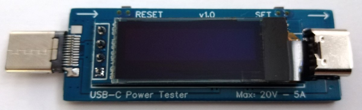
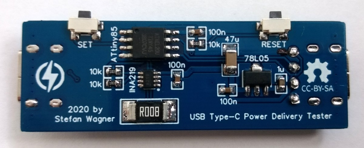
Simple USB-C Power Delivery Tester based on ATtiny25/45/85 and INA219.
The device measures
voltage
current
power
energy capacity
and displays the values on an OLED screen. You can switch between different screens by pressing the SET button.
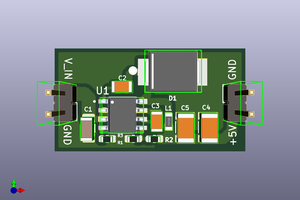
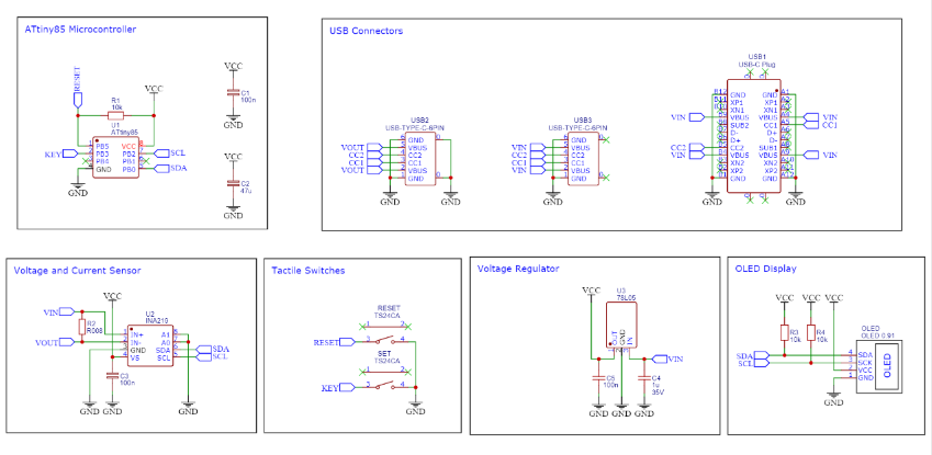
Circuit diagram


If you guys want to order the PCB please downlod the gerber file from here
I always prefer JLCPCB.com for my PCB needs, JLCPCB.com have best deals for their customers $2 for 1-4 Layer PCBs, free SMT assembly monthly.
SMT Assembly service of JLCPCB.com is cherry on top now get your PCB fully assembled and save your time and money Select components for your PCB from there Parts Library of 200k+ in-stock components they are offering $30 valued New User coupons & $24 SMT coupons every month $8.00 setup fee, and $0.0017 per joint
Now no need to order components separately for you PCB and get free from stress of soldering them on PCB just try PCB SMT assembly service and get you PCB with components pre assembled and ready for the project
👉 Try PCBA service of JLCPCB.com and save your time and money, get PCB ready for project, 200K+ components in library of JLCPCB.com as well as 3rd party parts to choose from. Assembly will support 10M+ parts from Digikey, mouser
👉 $30 valued New User coupons
👉 $24 SMT coupons every month
For more detials & offers please visit JLCPCB.com
Click here to visit JLCPCB.com
Bill of Material for PCB

Hardware
USB Connectors
The device is equipped with a USB-C receptacle (PCB version a) or plug (PCB version b) for the input and a USB-C receptacle for the output,
so that it can be plugged between the power supply and the consumer.
CC1 and CC2 communication channels are passed through so that supply and consumer can negotiate the bus power.

Voltage and Current Measurement
An INA219 is used to measure voltage and current. The INA219 is a current shunt and power monitor with an I²C-compatible interface.
The device monitors both shunt voltage drop and bus supply voltage, with programmable conversion times and filtering.
A programmable calibration value, combined with an internal multiplier, enables direct readouts of current in amperes.
The selected shunt resistance of 8mΩ enables both a very small influence on the circuit and a measurement with a resolution of 1mA.
For an accurate measurement, a shunt resistor with a low tolerance (1% or better) should be selected.
User Interface
The user interface utilizes two buttons and a 128x64 pixels OLED display.
An ATtiny24/45/85 microcontroller handles the user interface as well as the calculation and display of the values.
Software
Basic Principle
The INA219 continuously measures current and voltage and transmits the values to the ATtiny via I²C. From this, the ATtiny calculates the other values and displays them on the OLED screen.
I²C OLED Implementation
The I²C protocol implementation is based on a crude bitbanging method. It was specifically designed for the limited resources of ATtiny10 and ATtiny13, but it works with some other AVRs (including the ATtiny25/45/85) as well. The functions for the OLED are adapted to the SSD1306 OLED module, but they can easily be modified to be used for other modules. In order to save resources, only the basic functionalities which are needed for this application are implemented. For a detailed information on the working principle of the I²C OLED implementation visit TinyOLEDdemo.
Accuracy of Time and Capacity Determination
The internal oscillator of the ATtiny is used to determine energy and capacity. The accuracy of the internal oscillator is +/-10% with the factory calibration. This can be improved to +/-2% or better by manual calibration. The calibration value determined in this way can be set in the source code.
Compiling and Uploading...
Read more »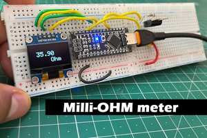
 Sagar 001
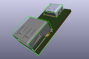
 mbsg99
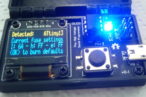
 Mrinnovative