 sandy
sandyPCA9685-Controller

Overview
Driving servo motors with the Arduino Servo library is pretty easy, but each one consumes a precious pin - not to mention some Arduino processing power.
The Adafruit 16-Channel 12-bit PWM/Servo Driver will drive up to 16 servos over I2C with only 2 pins.
The on-board PWM controller will drive all 16 channels simultaneously with no additional Arduino processing overhead.
What's more, you can chain up to 62 of them to control up to 992 servos - all with the same 2 pins!
The Adafruit PWM/Servo Driver is the perfect solution for any project that requires a lot of servos.
Pinouts
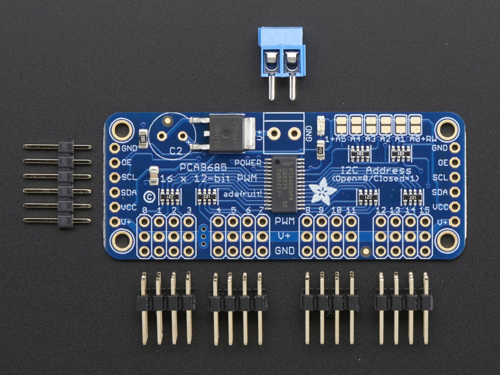
There are two sets of control input pins on either side. Both sides of the pins are identical! Use whichever side you like,
you can also easily chain by connecting up two side-by-side
Power Pins
GND - This is the power and signal ground pin, must be connected VCC - This is the logic power pin, connect this to the logic level you want to use for the PCA9685 output, should be 3 - 5V max! It's also used for the 10K pullups on SCL/SDA so unless you have your own pullups, have it match the microcontroller's logic level too! V+ - This is an optional power pin that will supply distributed power to the servos. If you are not using for servos you can leave disconnected. It is not used at all by the chip. You can also inject power from the 2-pin terminal block at the top of the board. You should provide 5-6VDC if you are using servos. If you have to, you can go higher to 12VDC, but if you mess up and connect VCC to V+ you could damage your board!
Control Pins
SCL - I2C clock pin, connect to your microcontrollers I2C clock line. Can use 3V or 5V logic, and has a weak pullup to VCC SDA - I2C data pin, connect to your microcontrollers I2C data line. Can use 3V or 5V logic, and has a weak pullup to VCC OE - Output enable. Can be used to quickly disable all outputs. When this pin is low all pins are enabled. When the pin is high the outputs are disabled. Pulled low by default so it's an optional pin!
Output Ports
There are 16 output ports. Each port has 3 pins: V+, GND and the PWM output. Each PWM runs completely independently but they must all have the same PWM frequency. That is, for LEDs you probably want 1.0 KHz but servos need 60 Hz - so you cannot use half for LEDs @ 1.0 KHz and half @ 60 Hz.
They're set up for servos but you can use them for LEDs! Max current per pin is 25mA.
There are 220 ohm resistors in series with all PWM Pins and the output logic is the same as VCC so keep that in mind if using LEDs.
Assembly
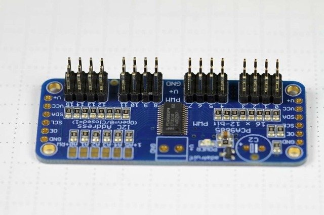
Install the Servo Headers Install 4 3x4 pin male headers into the marked positions along the edge of the board.

Add Headers for Control A strip of male header is included. Where you want to install headers and on what side depends a little on use: For breadboard use, install headers on the bottom of the board. For use with jumper wires, install the headers on top of the board. For use with our 6-pin cable, install the headers on top of the board. If you are chaining multiple driver boards, you will want headers on both ends.
Install Power Terminals If you are chaining multiple driver boards, you only need a power terminal on the first one.
Hooking it Up
Connecting to the Arduino The PWM/Servo Driver uses I2C so it take only 4 wires to connect to your Arduino:
"Classic" Arduino wiring: +5v -> VCC (this is power for the BREAKOUT only, NOT the servo power!) GND -> GND Analog 4 -> SDA Analog 5 -> SCL Older Mega wiring: +5v -> VCC (this is power for the BREAKOUT only, NOT the servo power!) GND -> GND Digital 20 -> SDA Digital 21 -> SCL R3 and later Arduino wiring (Uno, Mega & Leonardo): (These boards have dedicated SDA & SCL pins on the header nearest the USB connector) +5v -> VCC (this is power for the BREAKOUT only, NOT the servo power!) GND -> GND SDA -> SDA SCL -> SCL

Up to 16 servos can be attached to one board. If you need to control more than 16 servos, additional boards can be chained We have a spot on the PCB for soldering in an electrolytic capacitor. Based on your usage, you may or may not need a capacitor. If you are driving a lot of servos from a power supply that dips a lot when the servos move, n * 100uF where n is the number of servos is a good place to start - eg 470uF or more for 5 servos. Since its so dependent on servo current draw, the torque on each motor, and what power supply, there is no "one magic capacitor value" we can suggest which is why we don't include a capacitor in the kit.

#include <Wire.h>
#include <Adafruit_PWMServoDriver.h>

Adafruit_PWMServoDriver pwm1 = Adafruit_PWMServoDriver(0x40);
Adafruit_PWMServoDriver pwm2 = Adafruit_PWMServoDriver(0x41);

void setup() {  Serial.begin(9600);  Serial.println("16 channel PWM test!");
  pwm1.begin();  pwm1.setPWMFreq(1600);  // This is the maximum PWM frequency
  pwm2.begin();  pwm2.setPWMFreq(1600);  // This is the maximum PWM frequency
}
At last I would like to tell you something about PCB
Yes PCB are the heart of the electronics based project usually we hesitate to try custom PCB and opt to homemade solutions
like breadboard or Zero PCB earlier I also was in the same boat, I hesitate to try custom PCB my belief was they are much expensive.
but then I came to know about JLCPCB.com and I was totally surprised how low price PCB's are they offering
there PCB quality is best in market, now I always go with PCB for my project and JLCPCB.com is my trusted
PCB manufacturer, you can also try there PCB service for more details you can visit their website JLCPCB.com
I new user sign up using the given link will get welcome coupons from JLCPCB.com


SMT Assembly service of JLCPCB.com is cherry on top now get your PCB fully assembled and save your time and money Select components for your PCB from there Parts Library of 200k+ in-stock components they are offering $30 valued New User coupons & $24 SMT coupons every month $8.00 setup fee, and $0.0017 per joint
Now no need to order components separately for you PCB and get free from stress of soldering them on PCB just try PCB SMT assembly service and get you PCB with components pre assembled and ready for the project
👉 Try PCBA service of JLCPCB.com and save your time and money, get PCB ready for project, 200K+ components in library of JLCPCB.com as well as 3rd party parts to choose from. Assembly will support 10M+ parts from Digikey, mouser
👉 $30 valued New User coupons
👉 $24 SMT coupons every month
For more detials & offers please visit JLCPCB.com