 Arshmah Shahkar
Components Specifications:
Following are the major components used in my design. I have uploaded their symbols and footprints online on Inventhub in components management library for the users who want to implement my design. They can simply download and reuse components instead of designing them again.
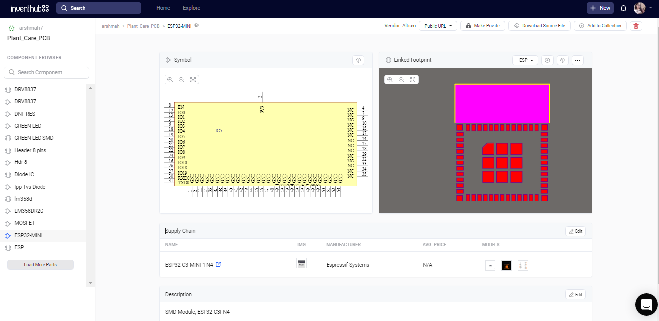
1. ESP32-WROOM Module:
- Processor 2.4 GHz
- WiFi IEEE 802.11 b/g/n-compliant
- Bluetooth 5 module
- 4 MB flash
- 15 GPIOs
- Onboard PCB antenna or external antenna connector
- Operating voltage/Power supply: 3.0 ~ 3.6 V
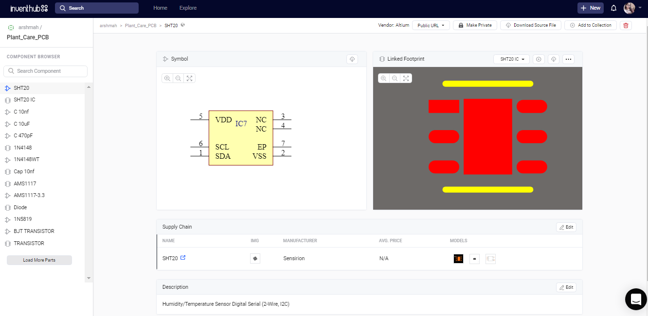
2. SHT20 Sensor IC:
- Digital Humidity and temperature sensor
- Humidity accuracy ±3%RH
- Response time (τ63%) 8sec
- Operating relative humidity range 0 - 100%RH
- Temperature accuracy 0.3°C
- Response time (τ63%) 5sec
- Operating temperature range -40 - 125°C
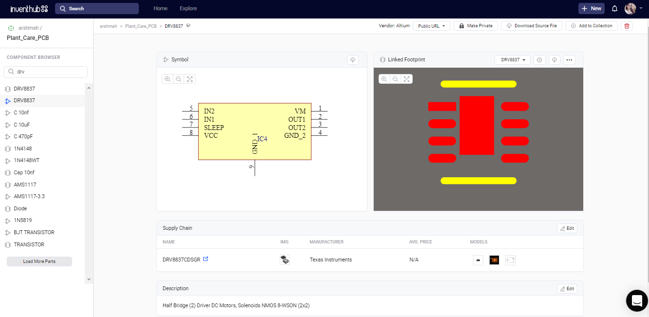
3. DRV8837 Motor Driver IC:
- H-bridge motor driver
- 1-A Maximum Drive Current
- 0- to 11-V Operating Supply-Voltage Range
- Standard PWM Interface (IN1/IN2)
- Protection Features; VCC Undervoltage Lockout (UVLO), Overcurrent Protection (OCP), Thermal Shutdown (TSD)
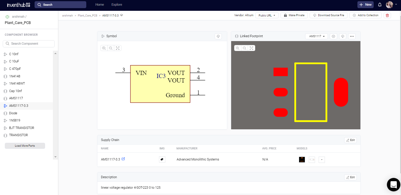
4. AMS1117 Voltage Regulator:
- Package SOT223
- 1-Amp 3.3-Volt
- Low Drop Out Voltage Regulator
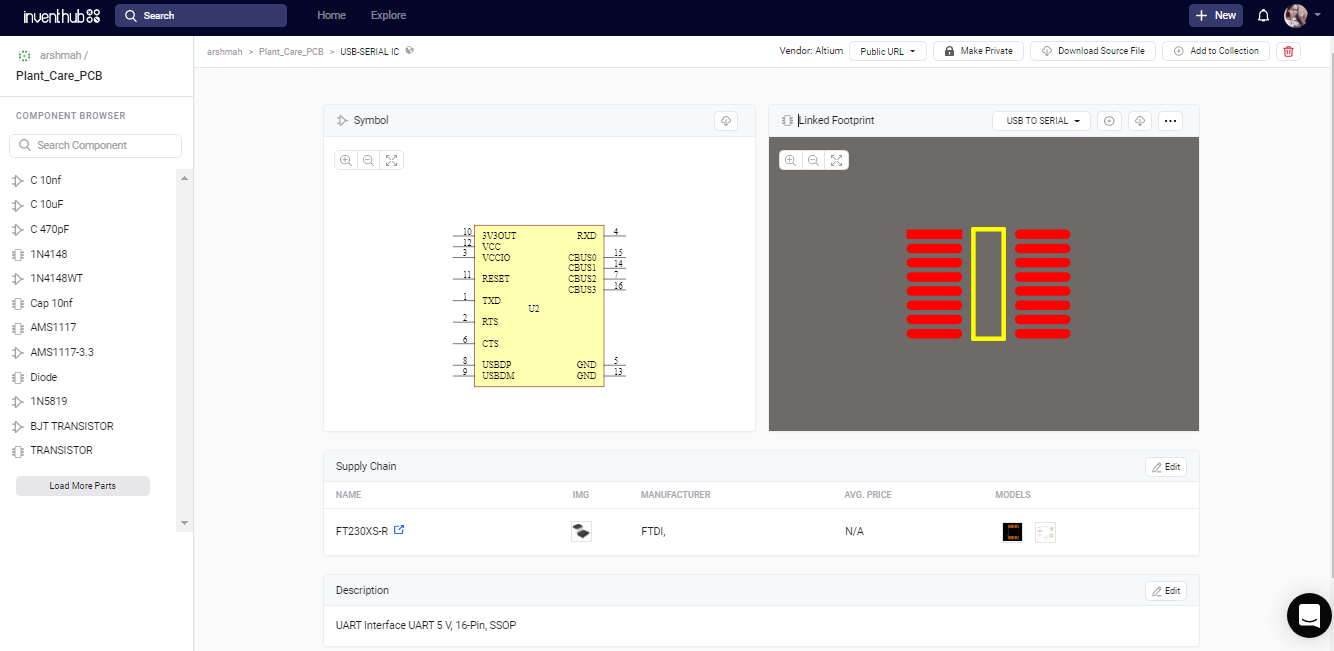
5. USB-UART IC:
- USB to serial UART interface
- Data transfer rates from 300 baud to 3 Mbaud at TTL levels
- Configurable I/O pin output drive strength; 4 mA to16 mA
- +5V Single Supply Operation
- Fully integrated 2048 byte multi-timeprogrammable memory
6. NE555 Timer IC:
- Input supply voltage, 4.5 V to 16 V
- High current timer output signal
- Timing From Microseconds to Hours
- Astable or Monostable Operation
- Adjustable Duty Cycle

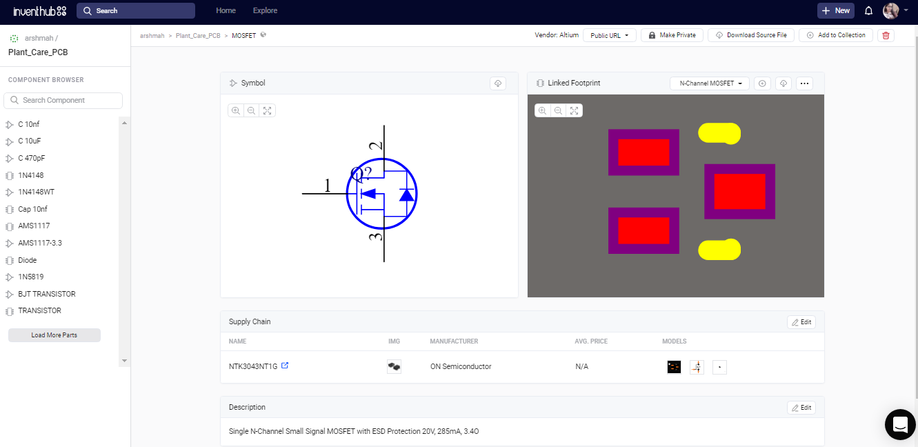
7. MOSFET:
- Power Mosfet 20 V, 285 mA
- N−Channel SOT−723
- ESD Protection
- Low Threshold Levels, VGS(TH) < 1.3 V
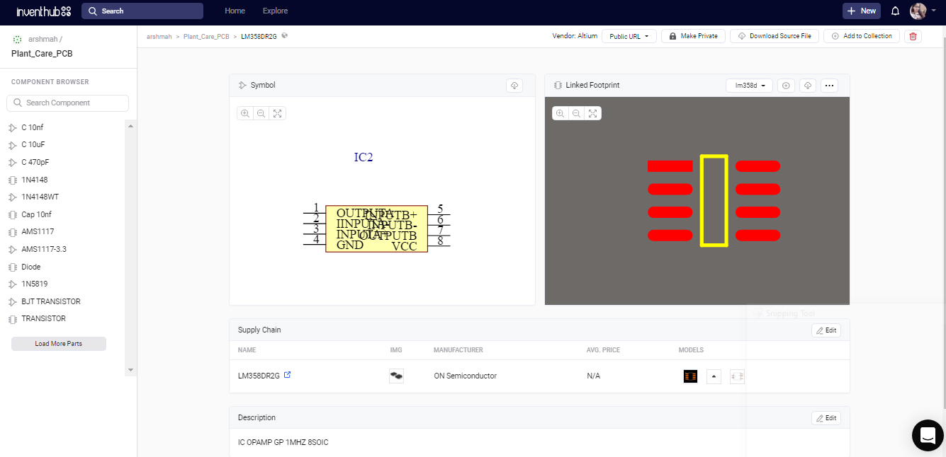
8. OP AMP LM358D IC:
- Single Supply Dual Operational Amplifier
- Short Circuit Protected Outputs
- True Differential Input Stage
- Single Supply Operation: 3.0 V to 32 V
Working of Schematic:
My main schematic file consists of a hierarchical design. I have created 7 sub-schematics that are linked to the main schematic file. While working with a complicated design iit’salways a good practice to make a hierarchical design. After creating my schematic in Altium, I have uploaded all my design files online on Inventhub for the users and the manufacturers.
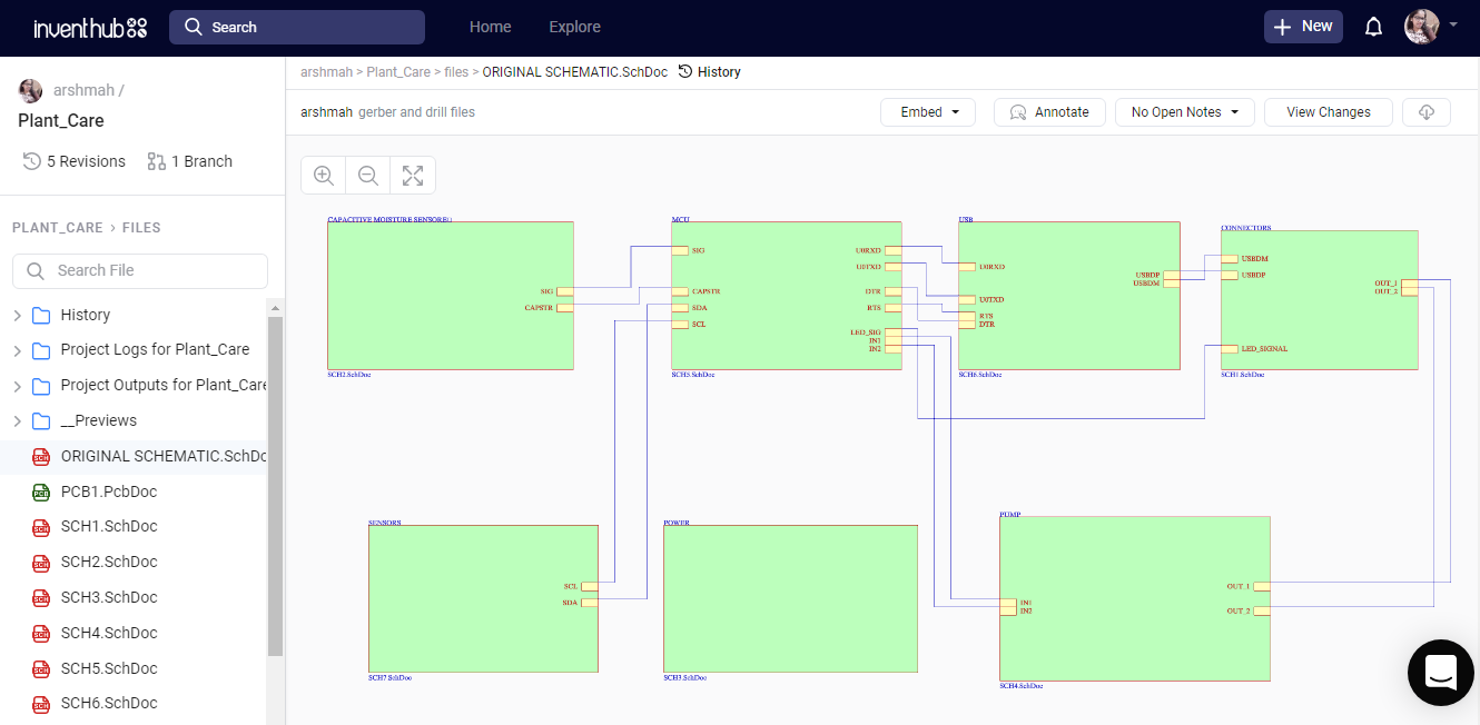
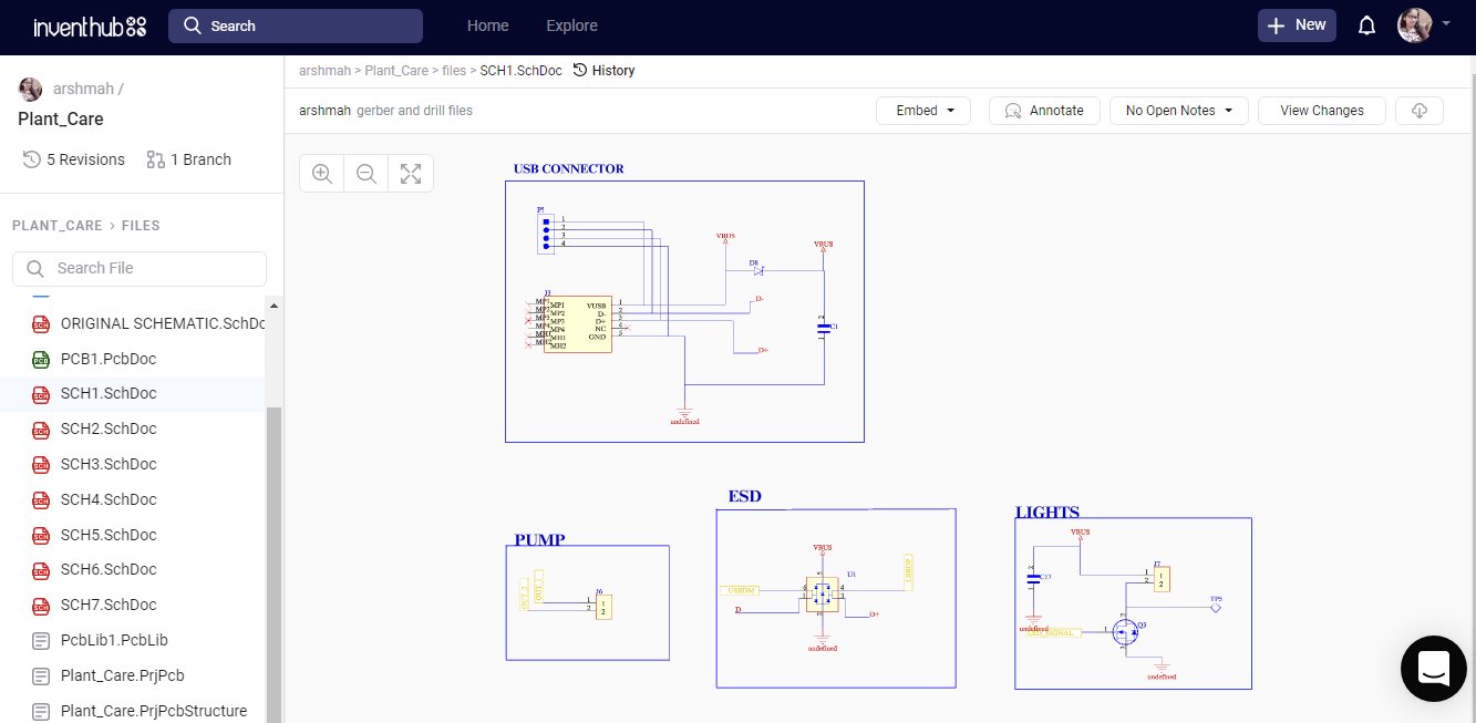
Connectors:
This schematic file has 4 blocks; USB connectors, ESD, lights, and pump.
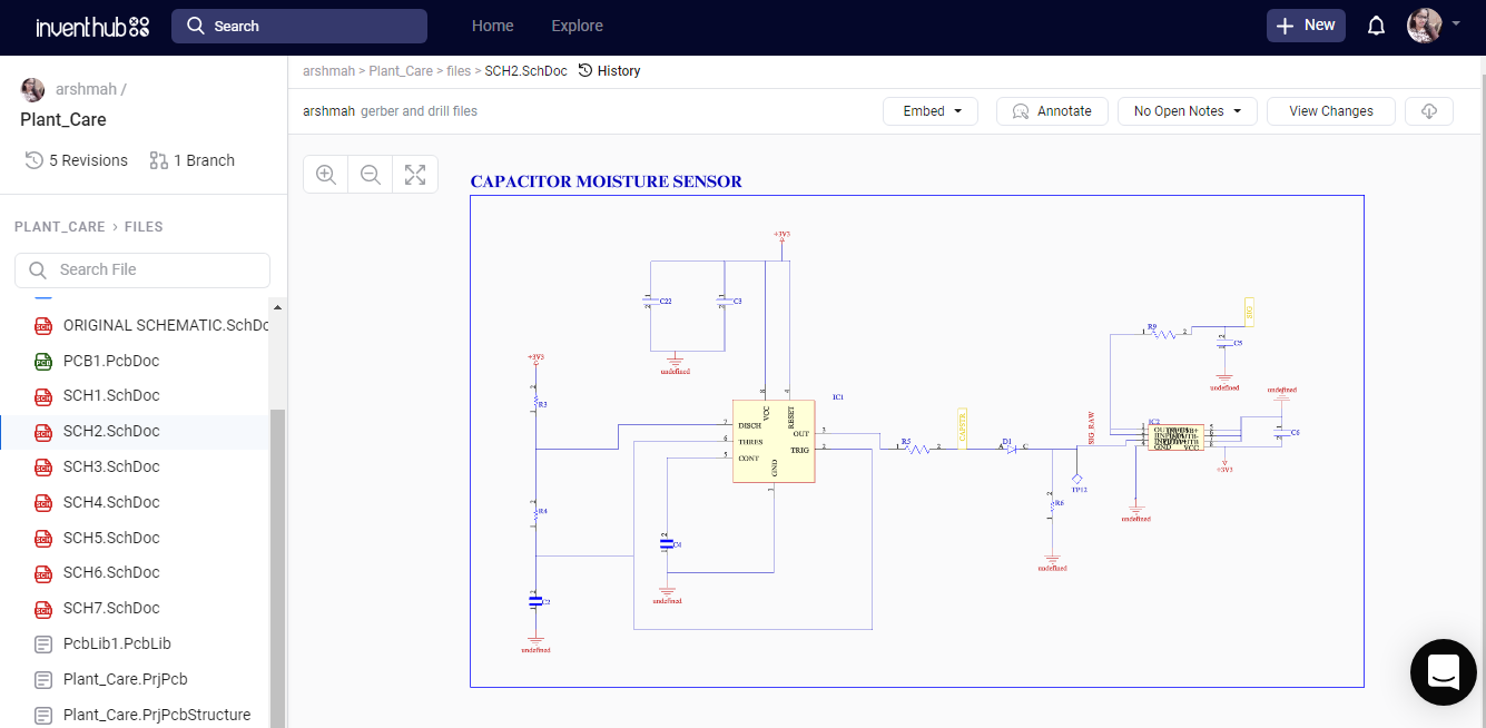
Capacitive Moisture Sensor:
There is only one block in this schematic file that contains NE555 timer IC and an LM358 operational amplifier. It is used as a soil moisture sensor. Two ports; SIG, and CAPSTAR are coming out of tis block that are further attached to the MCU block in main schematic.
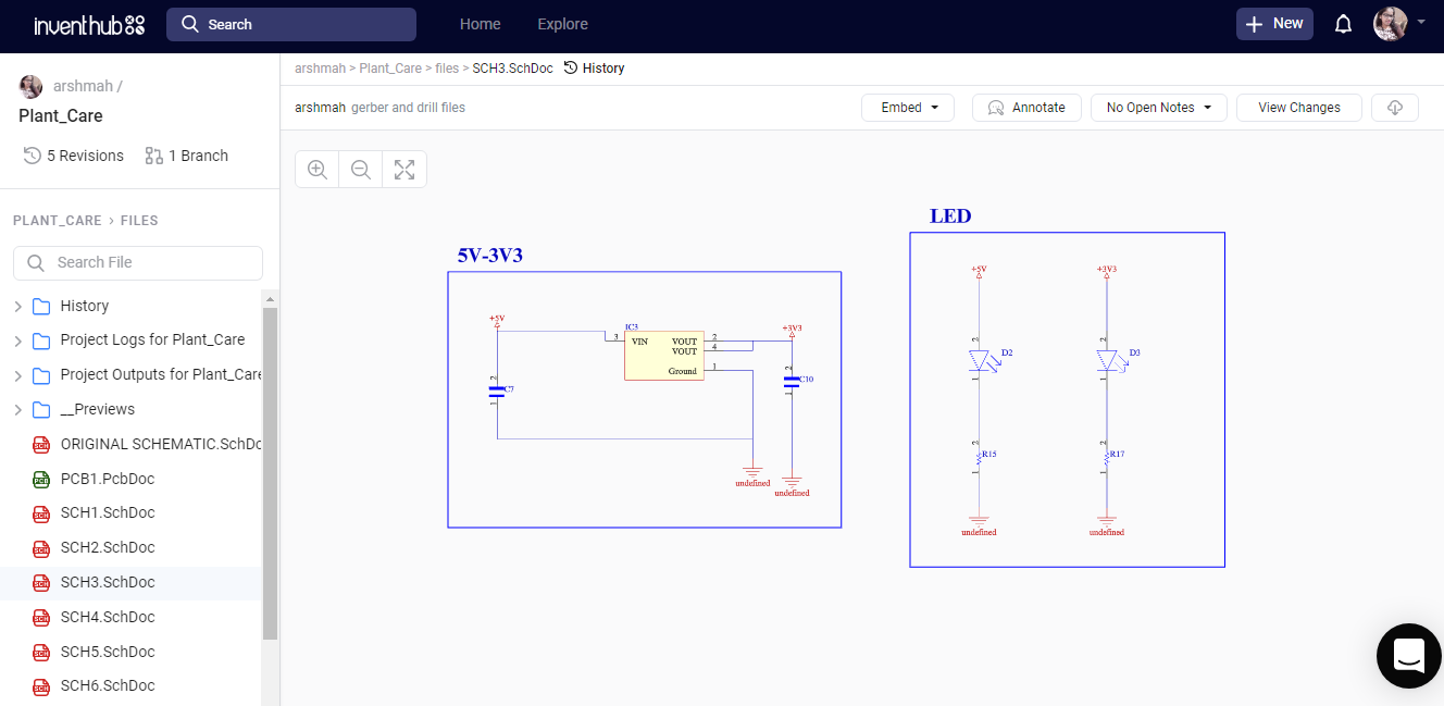
Power:
To provide power to the circuit, 5V or 3V3 Power supply and an LED block is attached in this schematic file.
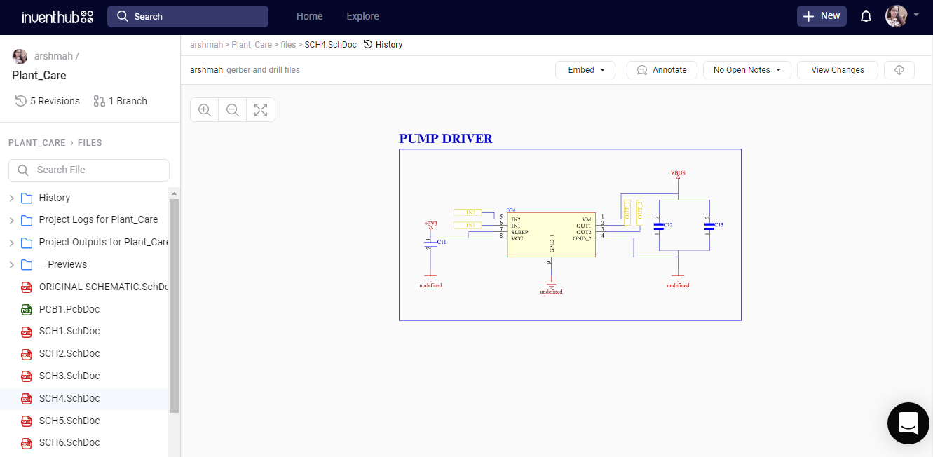
PUMP:
This schematic file consists of a pump driver block. Half bridge motor driver is attched to the capacitors. Input and output ports are attached to the I/O ports of MCU and connector block respectively in main schematic.
Microcontroller:
ESP32 MINI is the main component of this schematic file.
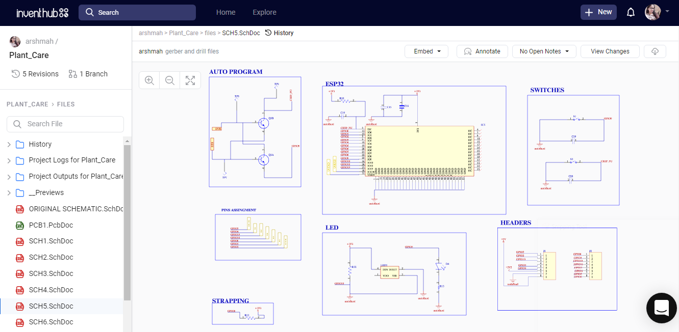
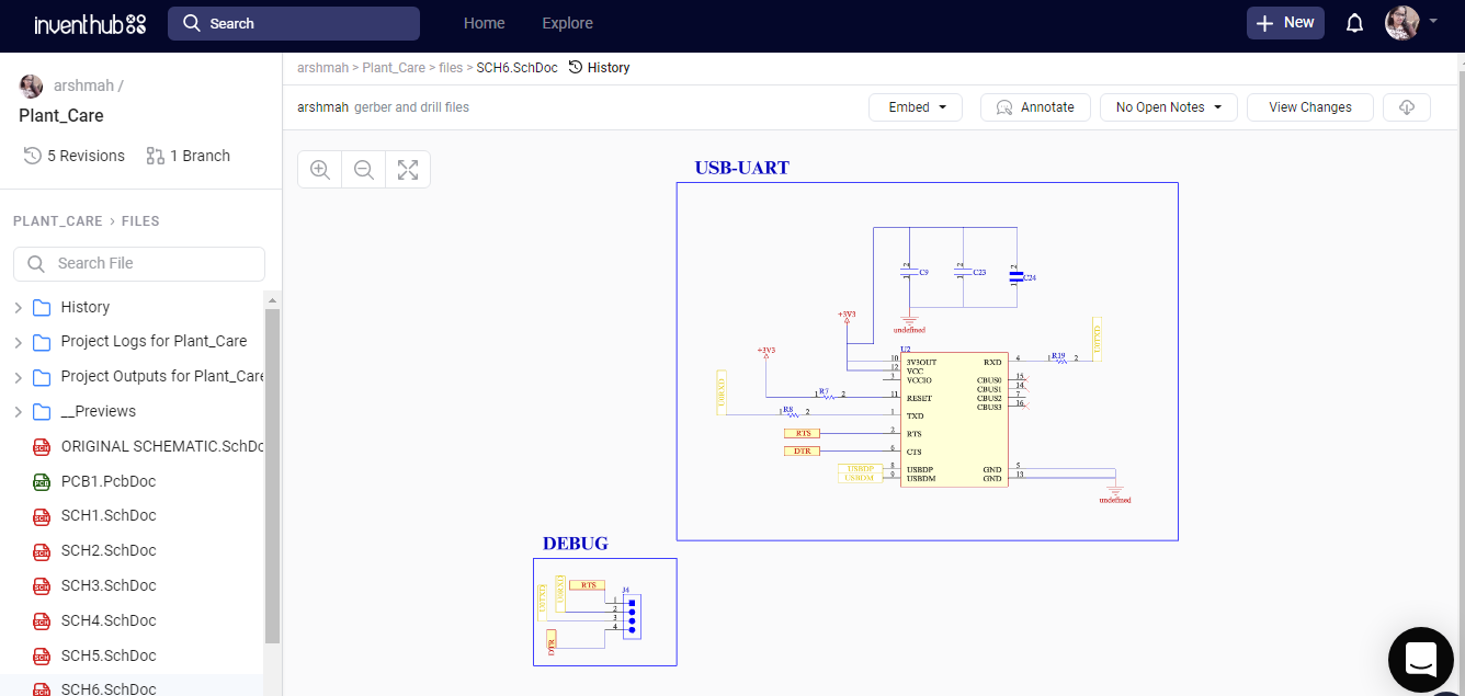
USB:
In this schematic a USB to serial IC is attached with capacitors and resistors. This is used for the communication between the MCU and USB.
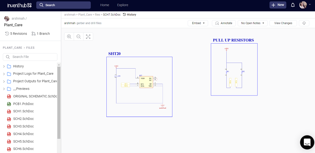
Sensors:
This sensor schematic is used to detect the temperature, humidity, and soil moisture. It has SHT20 sensor with pull up resistors.
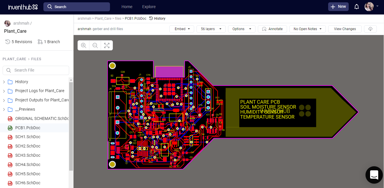
PCB Design:
I have converted my schematic file to the PCB file in Altium, where I can create connections on the board, define the shape of the board, arrange the components on the board, and can view my PCB in 3D view. I have uploaded my PCB file on Inventhub, where I can view my boards in different layers and can focus on a specific layer by disabling the other layers. Users and manufacturers can easily view or download my design for the implementation.
Revisions:
To create a backup of my design, I have uploaded different revisions of my design on Inventhub. This contains the changes in my design at different stages. If I want to get back the specific change I have made in my design, I can go to the revision and can select that particular file, and can download it to reuse it as my current design.
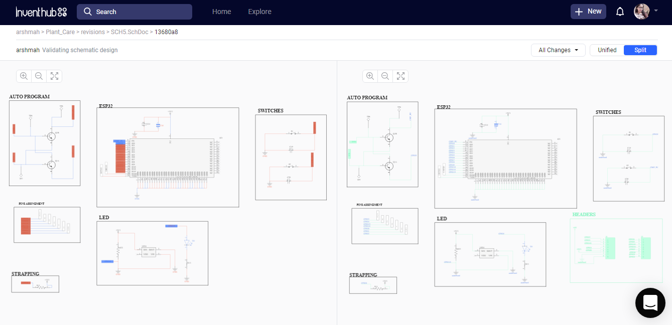
In the below figure, I have split my design into before or after making some changes; on the left side there isn’t any block of headers but on the right side block I have added headers. Moreover, on the right side, I can see some errors with the red color on the other hand right side has no errors. This will help me in comparing my design edits and I can easily decide which file I have to use for my design.
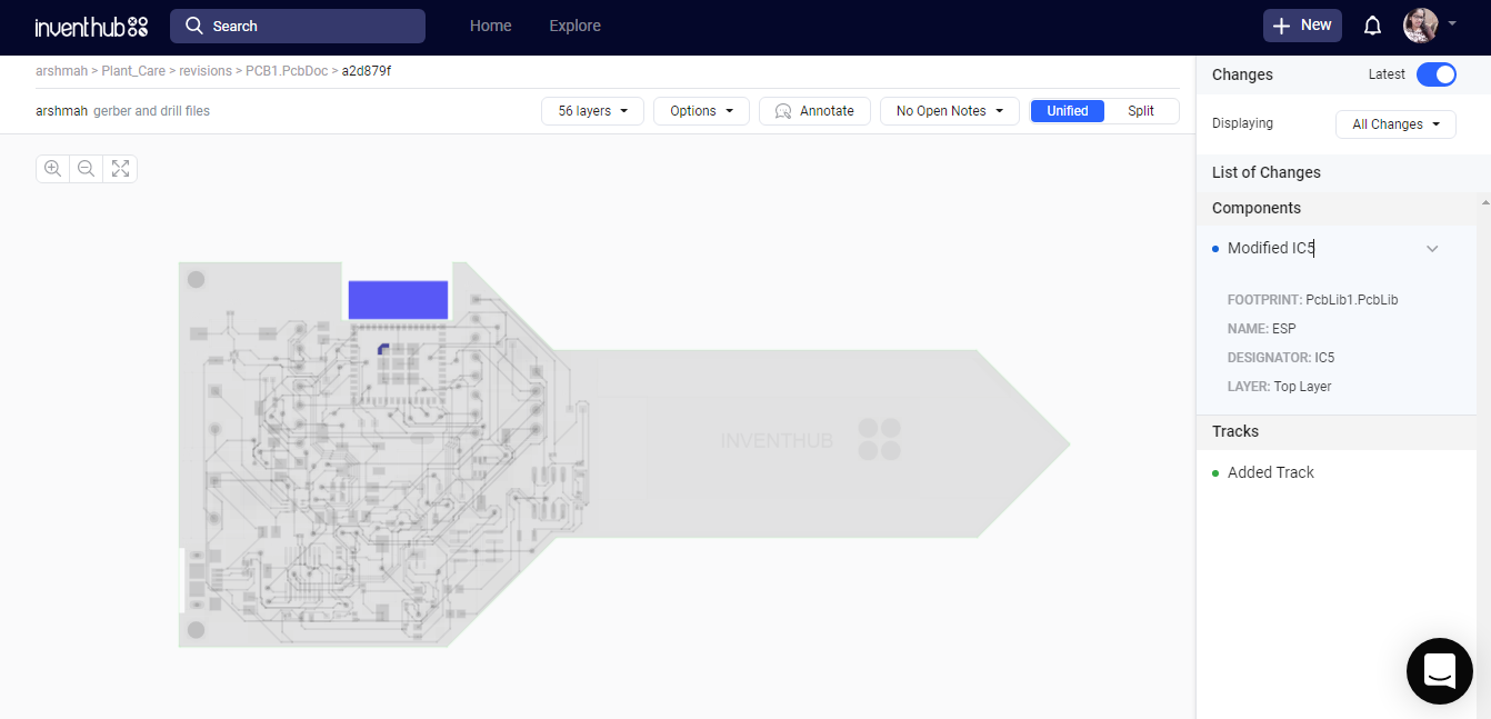
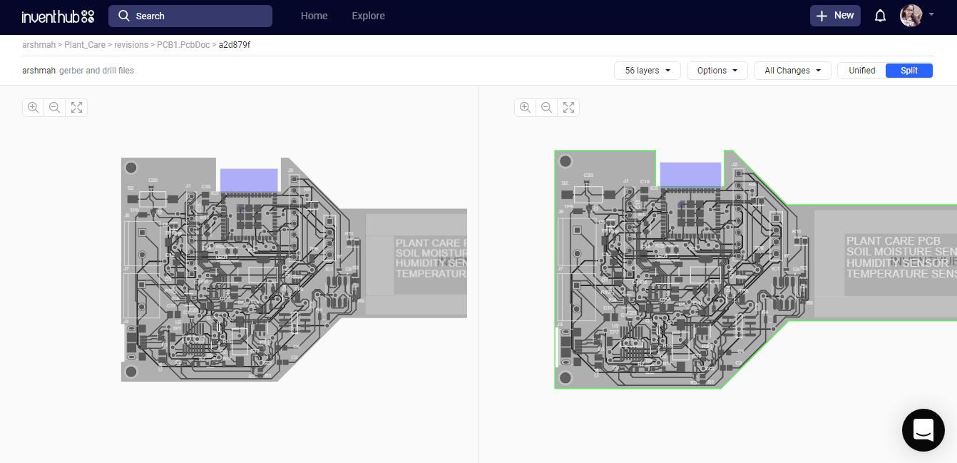
Below figure shows that there isn’t nay keep out layer in left side PCB design but I then I have added it in right side block. This is how I can also collaborate with people and they can tell me which part works better for my design and I can just add or remove any part.
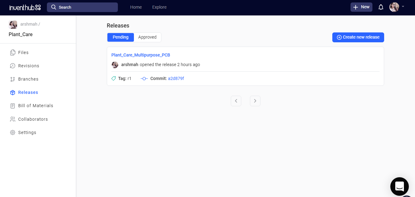
Release file:
I have created a release file of the project on Inventhub which contains all the design files in a ZIP file format. For the fabrication, I do not need to visit the manufacturer instead I can send him the release file of the project. He can easily download the files and can fabricate my PCB board.
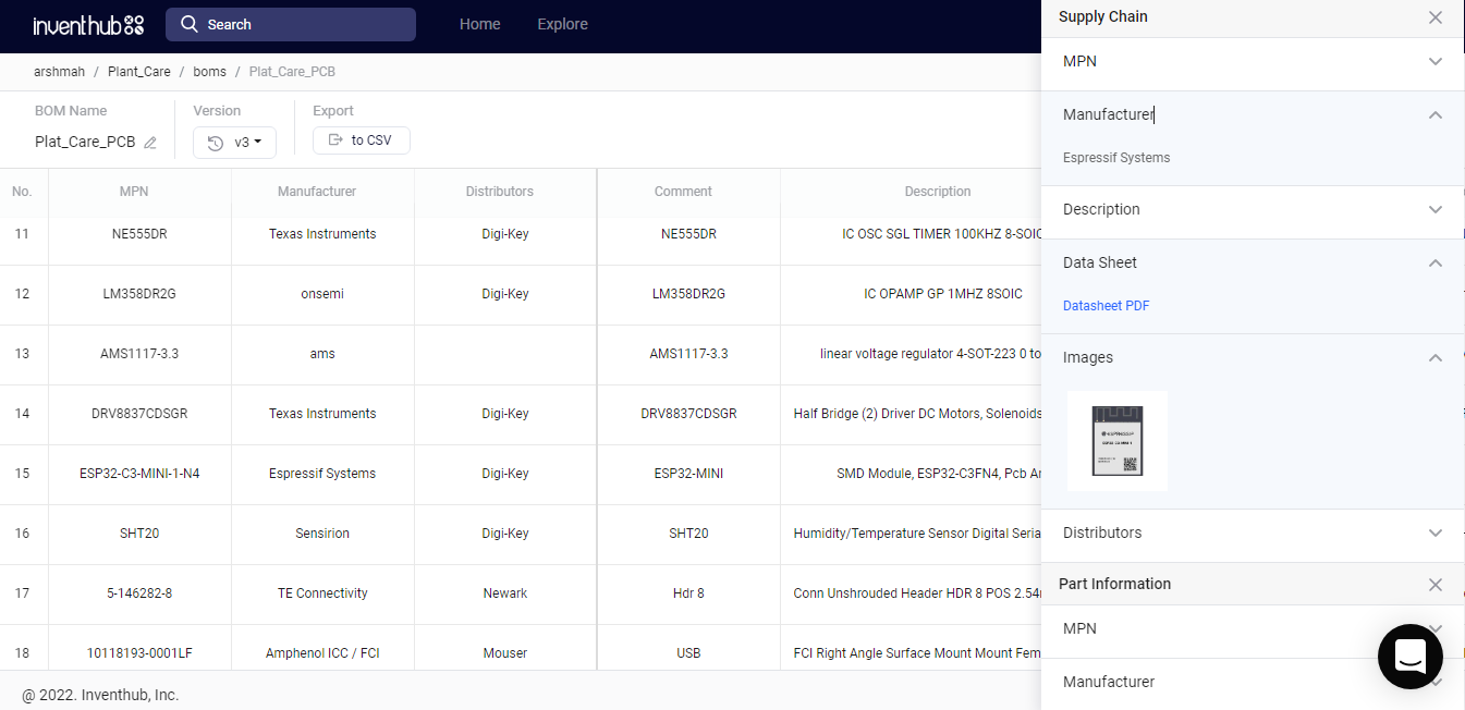
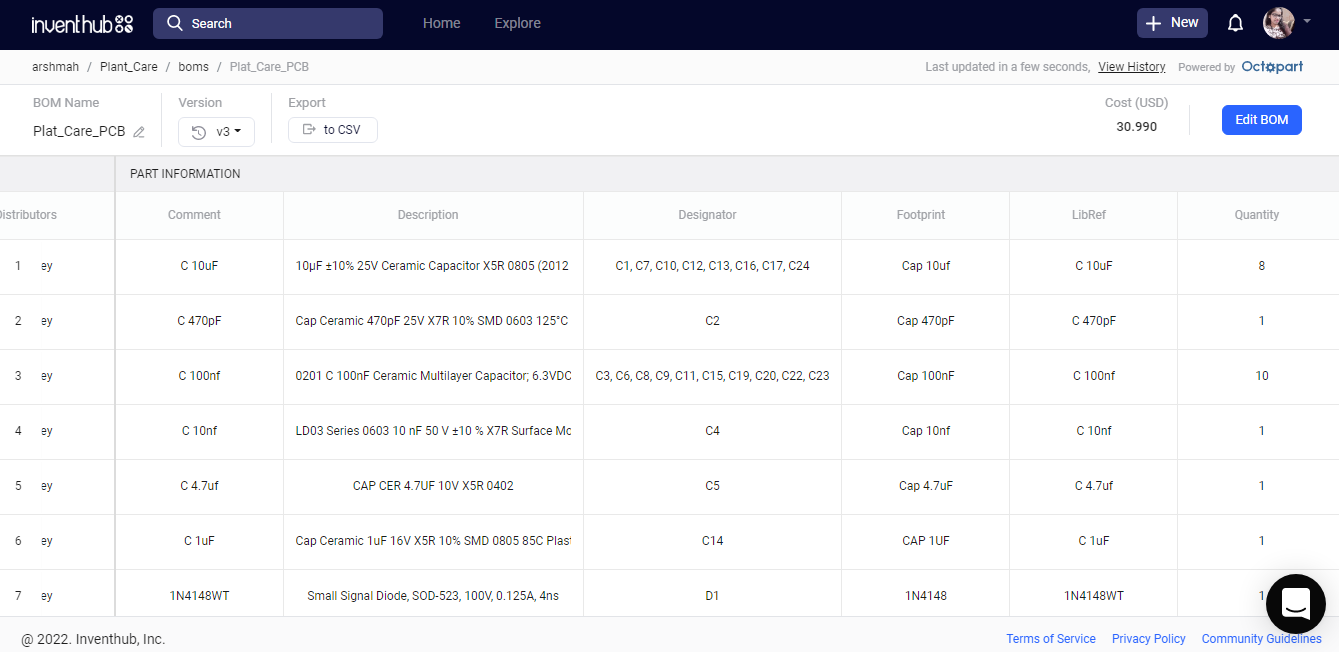
BOM file:
After the fabrication of the board, I created a list of components on Inventhub which contains the details of the manufacturer, supplier, manufacturer part number, pricing, and quantity. By just putting these details in the BOM file on Inventhub, I can easily calculate the total cost of my project automatically using the supply chain option. I can also view the datasheet of the component and can view its 3D model. Instead of visiting the component provider, I can send him this BOM file, he can download it in CSV file format and can deliver my components as per my design requirements.
Code Resources:
Thanks to elektroThing.