 Emilio P.G. Ficara
Part 1: Clock with binary display
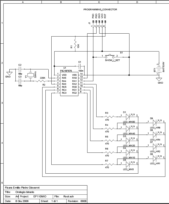
Wearable binary clock, built with Microchip PIC16F676 (or PIC16F630). The hours are displayed with 4 LEDs which are (from left to right) 8,4,2,1; so hours are shown from 1 to 12, no am and pm. The minutes are displayed with 5 LEDs that are (from left to right) 40,20,10,5,0; in practice, they show in 5 to 5 way and the exact hour (minute 00) turns ON led 0, because I don’t like to have the minutes row completely OFF.
To view the time, press shortly the button. Hours and minutes are on for 3 seconds, then all is off.
To adjust the time, press and hold the button until the top row only turns on and leds begin a binary counting from 1 to 12. When you reach the desired time, release the button.
After 5 seconds, the display automatically turns on the minutes row and pressing the button, they advance with the binary counting (5 min steps). When you reach the desired count, release the button.
Again, after 5 seconds both the led rows turns on to show hours and minutes (the seconds are cleared automatically) and everything is shut down. The time has been set.
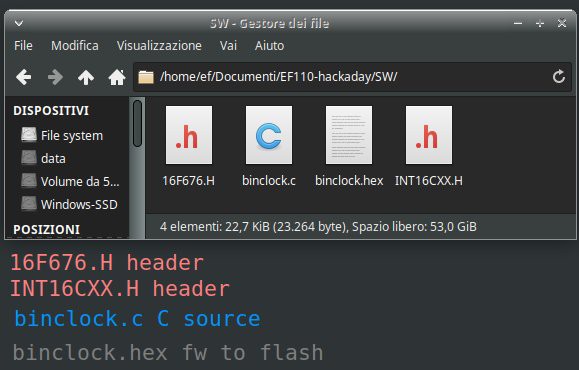
In the "files" section you can find the file EF110-hackaday.zip that contains two folders: HW with the diagrams and the Gerber file if you want to make your PCB and SW with the C sources. Here are the contents of SW folder:
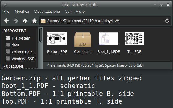
And here the HW folder:
The C source was compiled with CC5X Version 3.2I, (c) B Knudsen Data,Norway 1992-2005 (free edition).
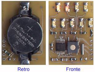
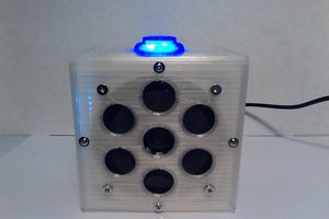
Here is the prototype (back / front):
This is the PCB design (just small image, but the 1:1 PDF is in zip file)
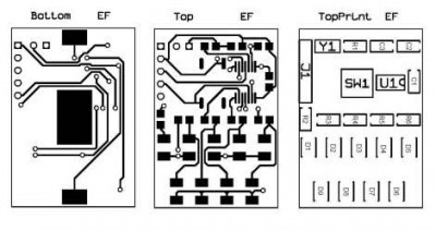
Note that the circuit uses conductive vias.
And finally the schematic diagram (PDF version is included in the downloadable ZIP)
Part 2: Color binary clock
What a bad time. I find myself stuck in the middle of a relocation. The virus spreaded and changed everyone's life, making a “freeze” of those who were moving from one city to another for a new job. So, now I only have a tiny travel workshop, but a lot of free time… What to do? I just have bits and pieces of test circuits, taken a little here and a little there and jumbled into a box. Searching, I found an old color led strip, bought years ago online and based on the GS1903 chip. There are 30 LEDs, but connected to three by three, so the usable "pixels" are only 10. I thought about making a clock, but given the lack of pixels, I had to do it with the output in binary code!
Hardware
Let's start with the prototype image:
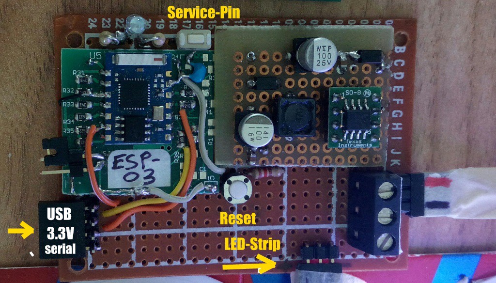
As we can see, the micro used is an ESP-8266, in the version mounted on an ESP-03 module. I know, this is very old and I think it is also out of production, but as I said, in the box of the old stuff there is just ... old stuff. However, respecting the GPIOs used, any other more recent module can be used. Let's see the complete wiring diagram:
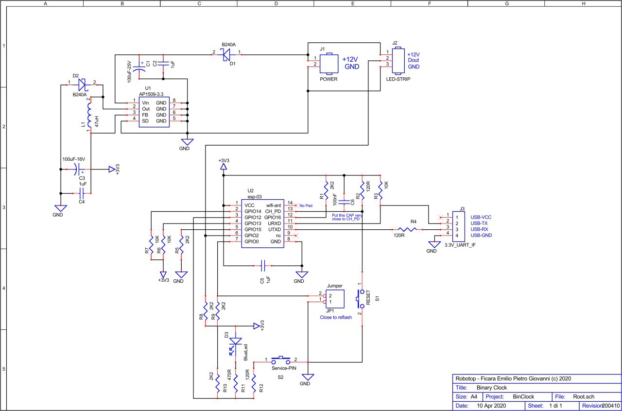
For a better view, you can download binclock-sch.pdf from “files” section.
Since the led strip typically runs at 12 Volts, I used a switching regulator to bring the power to the 3.3 Volts I need for the ESP8266. The circuit is very simple and as you can see, despite the SMD components, it is mounted on a prototype board. The ESP-03 module, on the other hand, was "cut out" from an old production board (of my design) recovered from reliability tests.
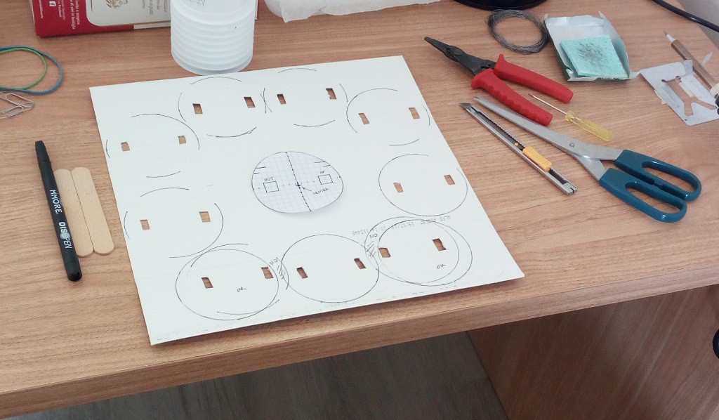
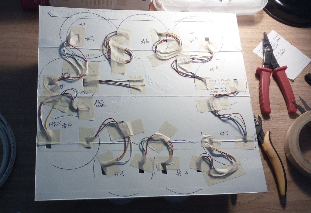
The most complicated part, of course, was the creation of the display. I cut out the strip in the various pieces of 3 leds and then I reconnected the wires. As "diffuser" elements I used (empty) yoghurt jars.
step1: element mapping
step 2: wiring (what a pain)
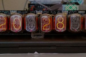
step 3: operational test (4.15 pm)
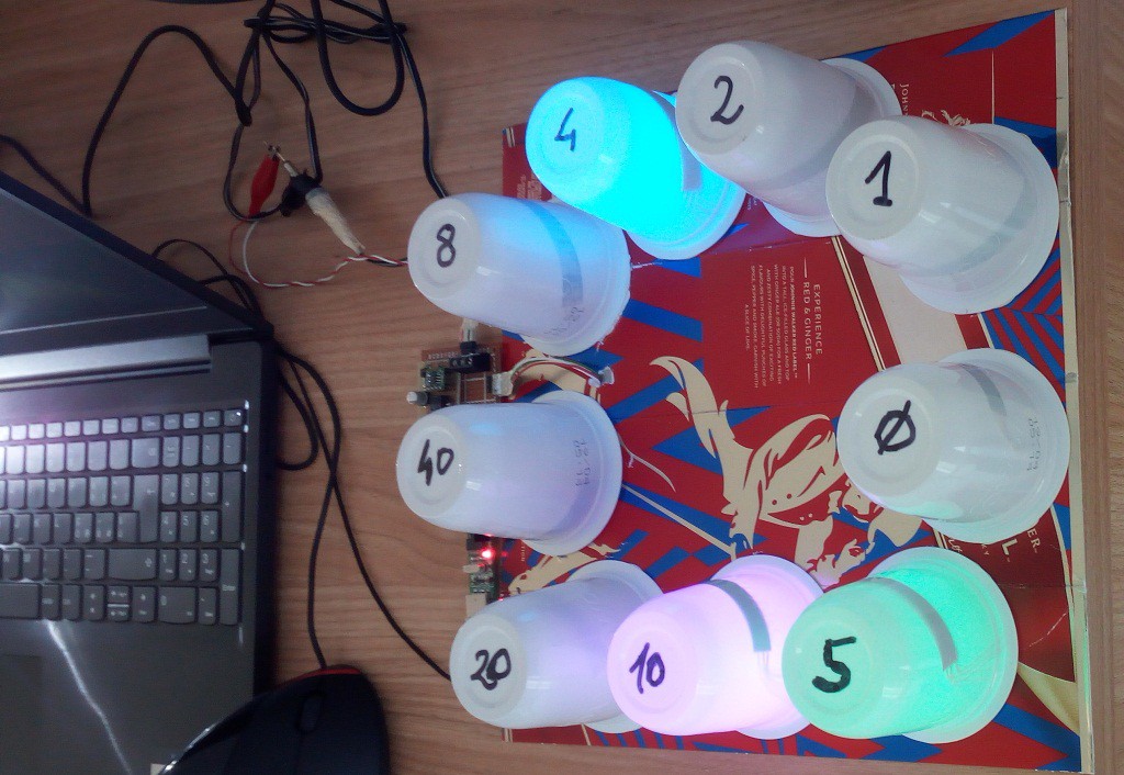
As you can see from the image, the minutes are counted from five to five and the hours range from 1 to 12 (all in binary, add the ON LEDs for the result). There is an additional led for the “zero minutes” situation because I don't like having the whole line off. The total pixels are therefore nine, the advanced one I keep it aside to do something...
Read more »
 TM
TM
 Robin Bussell
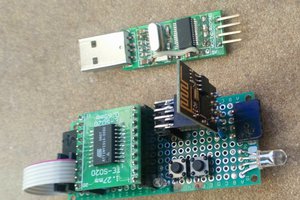
 ziggurat29
Searching for a painter and decorator in Ealing to change your home or office? Reach us today to examine your prerequisites and orchestrate a no-commitment quote.Check this: https://www.lgcdecorators.co.uk/painters-decorators-west-london/chelsea/