 Emilio P.G. Ficara
Part 1: Clock with binary display
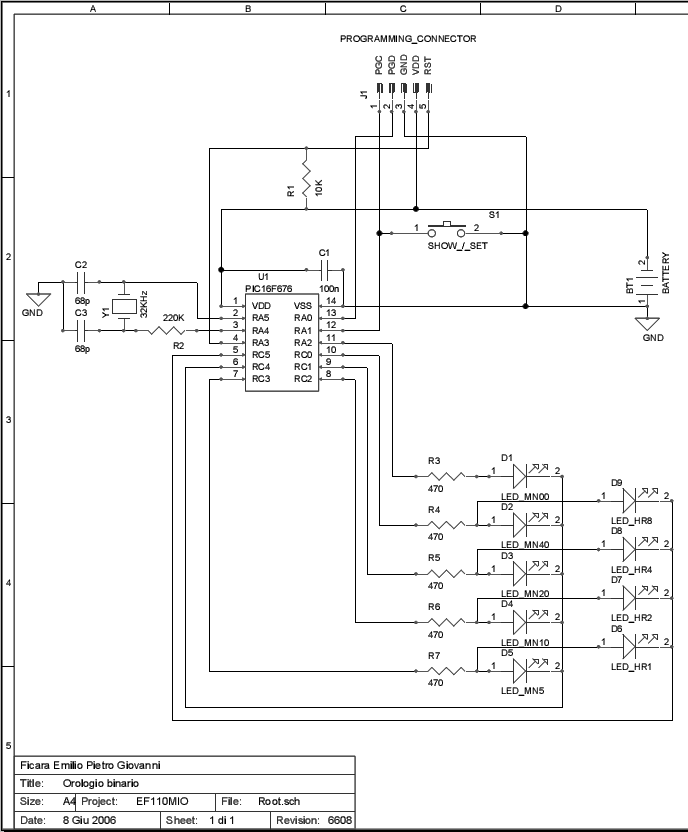
Wearable binary clock, built with Microchip PIC16F676 (or PIC16F630). The hours are displayed with 4 LEDs which are (from left to right) 8,4,2,1; so hours are shown from 1 to 12, no am and pm. The minutes are displayed with 5 LEDs that are (from left to right) 40,20,10,5,0; in practice, they show in 5 to 5 way and the exact hour (minute 00) turns ON led 0, because I don’t like to have the minutes row completely OFF.
To view the time, press shortly the button. Hours and minutes are on for 3 seconds, then all is off.
To adjust the time, press and hold the button until the top row only turns on and leds begin a binary counting from 1 to 12. When you reach the desired time, release the button.
After 5 seconds, the display automatically turns on the minutes row and pressing the button, they advance with the binary counting (5 min steps). When you reach the desired count, release the button.
Again, after 5 seconds both the led rows turns on to show hours and minutes (the seconds are cleared automatically) and everything is shut down. The time has been set.
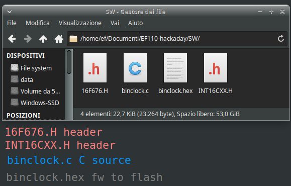
In the "files" section you can find the file EF110-hackaday.zip that contains two folders: HW with the diagrams and the Gerber file if you want to make your PCB and SW with the C sources. Here are the contents of SW folder:
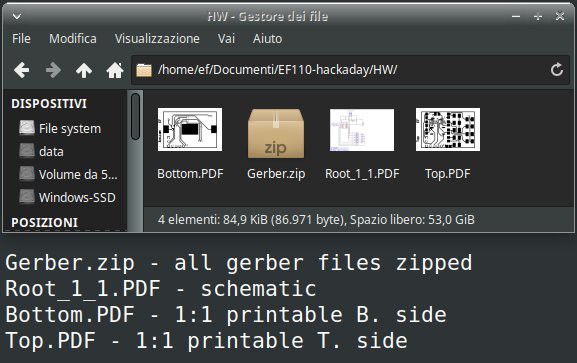
And here the HW folder:
The C source was compiled with CC5X Version 3.2I, (c) B Knudsen Data,Norway 1992-2005 (free edition).
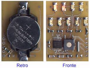
Here is the prototype (back / front):
This is the PCB design (just small image, but the 1:1 PDF is in zip file)
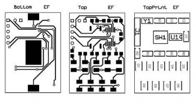
Note that the circuit uses conductive vias.
And finally the schematic diagram (PDF version is included in the downloadable ZIP)
Part 2: Color binary clock
What a bad time. I find myself stuck in the middle of a relocation. The virus spreaded and changed everyone's life, making a “freeze” of those who were moving from one city to another for a new job. So, now I only have a tiny travel workshop, but a lot of free time… What to do? I just have bits and pieces of test circuits, taken a little here and a little there and jumbled into a box. Searching, I found an old color led strip, bought years ago online and based on the GS1903 chip. There are 30 LEDs, but connected to three by three, so the usable "pixels" are only 10. I thought about making a clock, but given the lack of pixels, I had to do it with the output in binary code!
Hardware
Let's start with the prototype image:
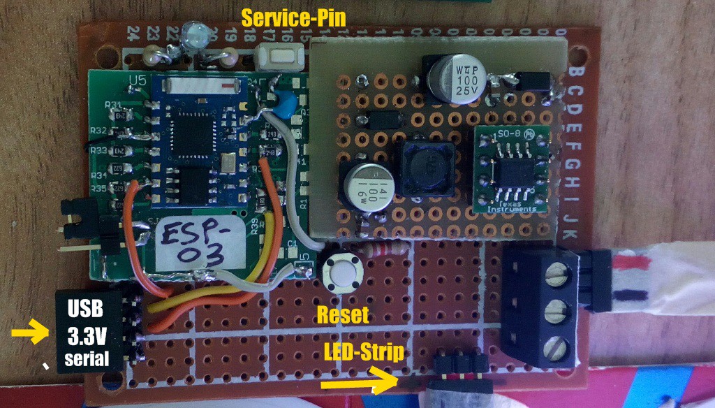
As we can see, the micro used is an ESP-8266, in the version mounted on an ESP-03 module. I know, this is very old and I think it is also out of production, but as I said, in the box of the old stuff there is just ... old stuff. However, respecting the GPIOs used, any other more recent module can be used. Let's see the complete wiring diagram:
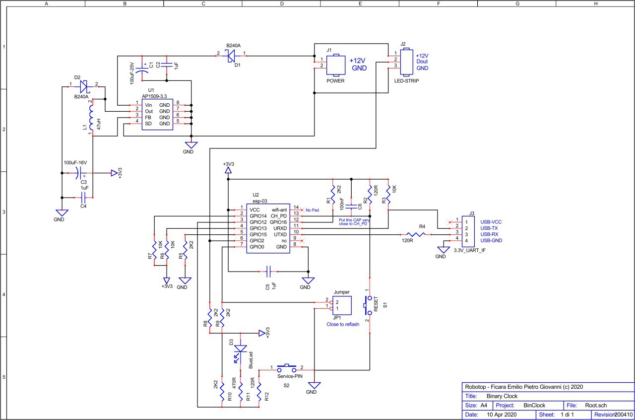
For a better view, you can download binclock-sch.pdf from “files” section.
Since the led strip typically runs at 12 Volts, I used a switching regulator to bring the power to the 3.3 Volts I need for the ESP8266. The circuit is very simple and as you can see, despite the SMD components, it is mounted on a prototype board. The ESP-03 module, on the other hand, was "cut out" from an old production board (of my design) recovered from reliability tests.
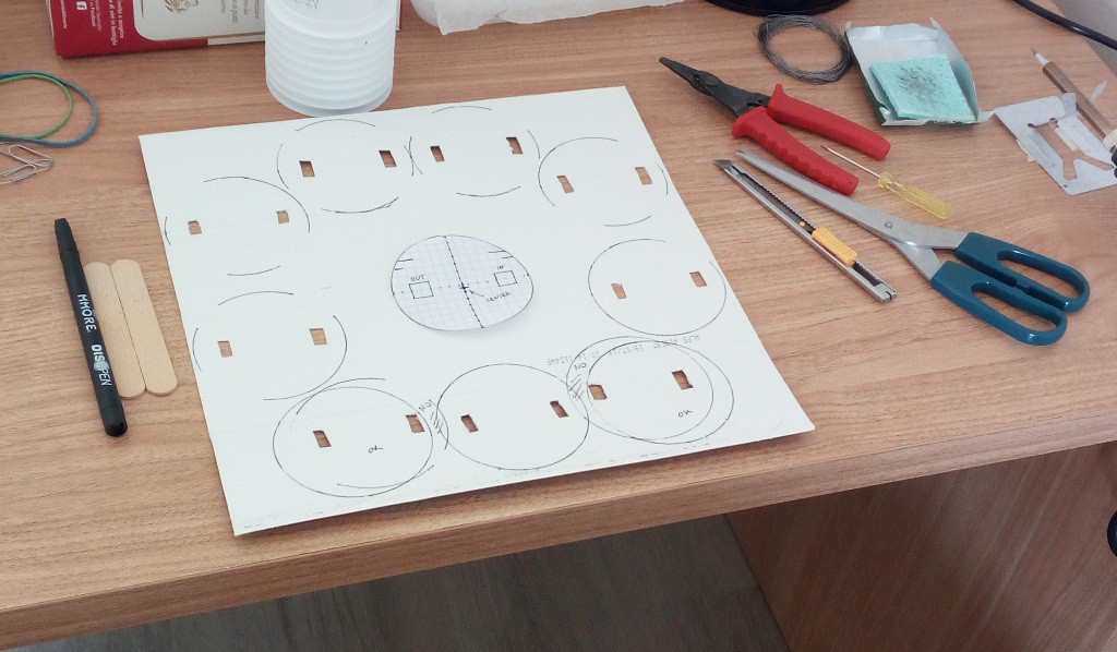
The most complicated part, of course, was the creation of the display. I cut out the strip in the various pieces of 3 leds and then I reconnected the wires. As "diffuser" elements I used (empty) yoghurt jars.
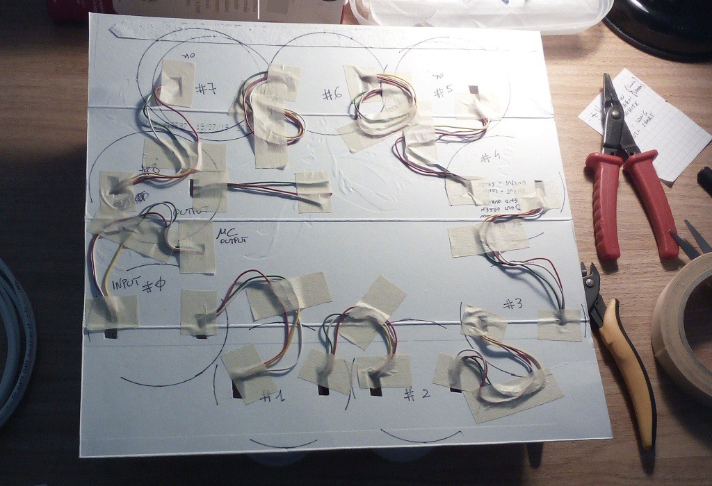
step1: element mapping
step 2: wiring (what a pain)
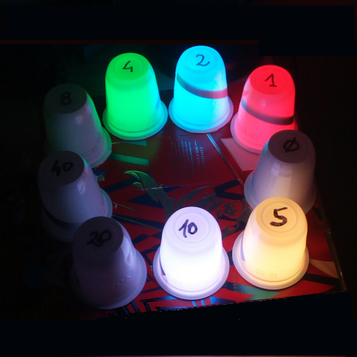
step 3: operational test (4.15 pm)
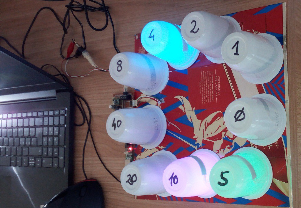
As you can see from the image, the minutes are counted from five to five and the hours range from 1 to 12 (all in binary, add the ON LEDs for the result). There is an additional led for the “zero minutes” situation because I don't like having the whole line off. The total pixels are therefore nine, the advanced one I keep it aside to do something else...
Firmware
I made the firmware on the Arduino development platform. The program, as far as the clock part is concerned, is very simple. It gets a little more complicated for managing the various customization commands through the serial port. Furthermore, there is also the possibility to connect (through WiFi and the home router) to a DAYTIME server which allows you to keep the clock always synchronized. The heart of the Real Time Clock (RTC) is really simple: a few lines of program:
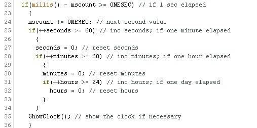
Using the millis() function gives good counting accuracy. Since there is also the possibility to re-synchronize with a Time Server (if set, every 8 hours) there will never be the need to "adjust the time". However, even without an internet connection, the clock is quite accurate and, as it shows the minutes at five to five, it will take a long time before you have to adjust it manually.
Note: upon reset, the circuit goes into a condition of "you must adjust the time" which is displayed with all the LEDs on. This allows the use as a simple “colored led strip”, with the colors programmable through the serial port. If you never perform a time adjustment (manual or automatic), it will always remain in this state. Everything will be clearer to you after reading the part about the control software.
Given the complexity of the complete program, I do not publish the source "sketch", but you will find in the attachment the .bin file to program the micro of your circuit. The program is compiled for a generic ESP8266 with 1 MB of flash, so you can also use the .bin file to program other modules, different from the ESP-03 shown on the diagram. To program the module you will need to connect a USB-TTL interface between your PC and the hardware. I recommend: remember to set the interface so that the serial signals are at 3.3 Volts. Typically, there is a jumper or switch on board for this purpose.
For programming, you will need software freely downloadable from the internet. There is no need to install the Arduino development platform, just download a programming software. You can find it on the website of Espressif (the manufacturer of the chip) or on various forums. Here's what you need to do to program the micro: first of all, you need to insert the “prog” jumper on the module and then press “reset”. In this way, the micro enters the programming phase and therefore waits for commands and data from the serial line. Then you can run the program:
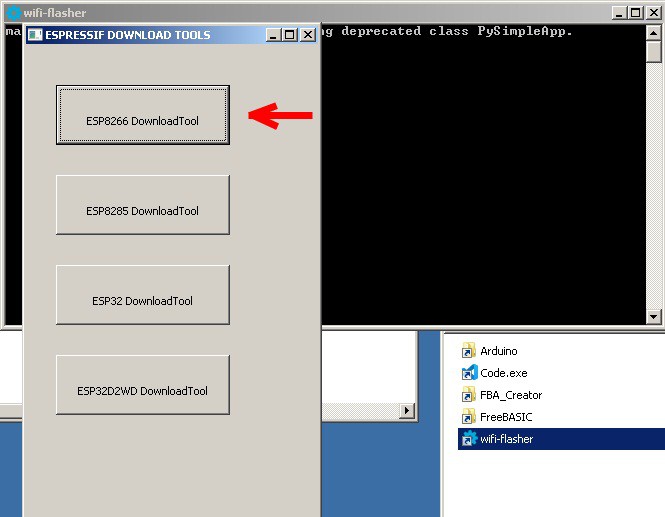
Here you choose the version for ESP8266, with the appropriate button. Now the window appears with the various fields to be filled in:
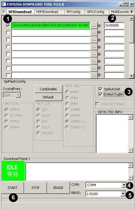
Here we have to follow this sequence:
1) enter here the path to the BinClock_xxxxxx.bin file downloaded from the "files" section
2) enter here the starting address (0x00000)
3) tick the two checkboxes as shown in the image
4) enter here the COM Port used (USB serial interface)
5) enter here the serial speed (115200)
6) click start
If everything was done correctly, the program will start doing its job and shortly afterwards it will finish like this:
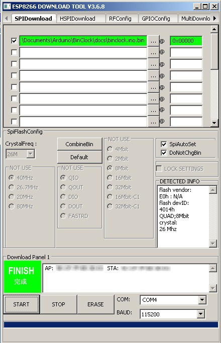
At this point, you can close the program and remove the "prog" jumper from the circuit, then you can press the "reset" again. All the LEDs on the strip will light up in white and the blue LED on the "service pin" will start flashing once per second. In this situation, the LEDs of the strip will all remain on and there will be no synchronization of the time, because there is a lack of essential data (SSID, PASW, DAYTIME server) that we will have to program via software, giving commands in serial through a terminal or using the PC application (Windows) that you find in the attachment (zipped together with the .bin file).
Software
As I said, you could use any terminal, set to 115200, N, 8,1 to give the customization commands. All commands begin with the + sign and are followed by two letters and eventually by the data and finally by the terminator (CRLF). Since remembering all the commands by heart is a bit tricky, I decided to write a Windows application to make things easier. This App is a "pure executable" (an .exe) and does not need installation. It can also be "launched" from a USB stick. I wrote this software in FreeBasic with FireFly. Here is a screenshot of the program:
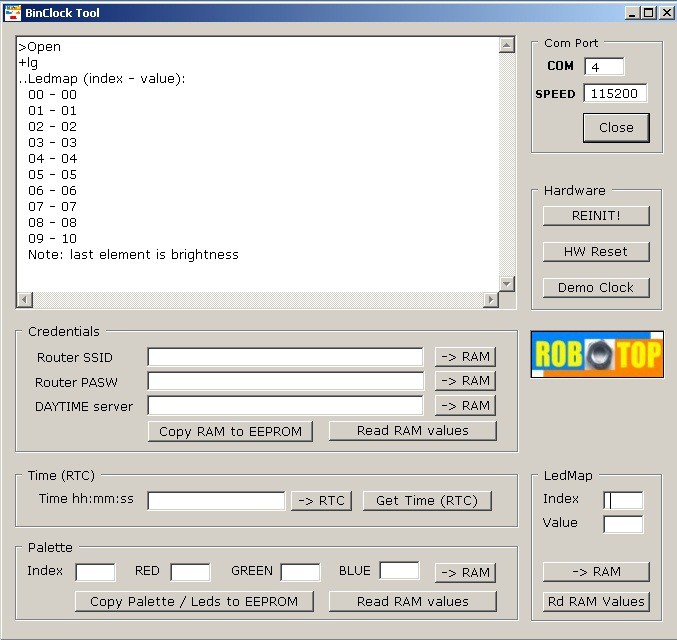
At the top left we find the message window, where we will see both the commands sent by us (on serial) and the responses received from the micro. The available commands are grouped by sections. Let's see them:
Com Port - serial port settings
Hardware - commands for the hardware section
Credentials - commands for SSID, PASW, DAYTIME server
Time - commands for RTC
LedMap - commands to modify the led map
Palette - commands for changing the color palette
Before seeing the individual commands in detail, a clarification is useful: some commands write values in RAM and others transfer RAM to EEprom. The ESP8266 chip does not have a real EEprom, but it is the same FLASH that is managed "as if it were" an EEprom through a system library. At reset, the first time the device is turned on, the EEprom is filled with the “default” values and then its contents are copied to the variables in RAM, which are the ones used by the program. At each subsequent reset, the data is always read from the EEprom on the RAM, thus reloading the previously saved situation. Therefore, if we change a value in RAM and do not save it on EEprom, the next time it is turned on we will lose the change made.
--ComPort section
This is the section that allows us to define the serial port to use and the speed it must have. After entering / modifying the data, press “open” and you will receive an OK or error message. If OK, the button text changes from “open” to “close”. Obviously, in order to send commands, the ComPort must be “open”.
--Hardware section
Here we have three commands that impact hardware. These are:
REINIT! - deletes the EEprom first write key, which thus returns to the initial conditions. All data in EEprom will be replaced with default values. After clearing the EEprom, the circuit resets itself automatically. The command from serial is +kc (followed by CRLF).
HW Reset - Causes a hardware reset. As a consequence of the reset, the RAM is filled up again with the values read from the EEprom. The command from serial is +hr (CRLF).
Demo Clock - Enable the demo clock function. In practice, the clock starts to "run" at the rate of 5 minutes per second, so as to quickly view all the combinations of the display, from 12:00 to the next 11:55 and so on. To exit the “demo” mode, the circuit must be reset (with the button or with the serial command). The command from serial is +dc (CRLF).
--Credentials section
Here we have five commands and three text entry boxes. Let's see its functions:
Read RAM values - Reads from the RAM the data relating to the SSID and PASSWORD of the WiFi modem router to which we connect, then it also reads the address of the site that we want to use as a DAYTIME server. The default value for all data is "no", indicating that we do not use the Internet and do not update the time automatically. The list of values is shown on the message window. The command from serial is +rc (CRLF).
-> RAM (side Router SSID) - transfers the contents of the Router SSID edit box to the corresponding variable in RAM. The command from serial is +idtext (CRLF).
-> RAM (side PASW Router) - transfers the contents of the PASW Router edit box to the corresponding variable in RAM. The command from serial is +pwtext (CRLF).
-> RAM (side DAYTIME server) - transfers the contents of the DAYTIME server edit box to the corresponding variable in RAM. Use a DAYTIME server that provides the time with a CEST value (Central Europe). If you use a server that provides UTC value, two hours will be subtracted, regardless of daylight saving time! I use the time.ien.it server which provides the CEST time. The command from serial is +datext (CRLF).
Copy RAM to EEPROM - copies all three variables from RAM to EEprom, so they can be automatically reloaded at the next circuit reset. The command from serial is +wc (CRLF).
--Time section (RTC)
Here we have two commands and a text entry box. Let's see its functions:
-> RTC - transfers the contents of the Time hh: mm: ss edit box to the RAM variables of hours, minutes and seconds (RTC). This writing causes the exit from the condition of "waiting for time adjustment" which occurs at each reset of the circuit and consequently the led strip lights up with the set value. The command from serial is +tshh:mm:ss (CRLF).
Get Time (RTC) - reads the current RAM value for hours, minutes and seconds. The read value show in the message window. The command from serial is +tg (CRLF).
--Palette section
The Palette section is used to specify the color combinations we want to use in our watch. There are 16 rows from (00 to 15) for three columns (Red, Green, Blue) to which we can assign values between 000 and 255 according to our preferences. The color determined by the triplet can then be used in the LED map through its index (row number). For example, if in line 00 we have written R 255, G 000, B 000, then in the LED map we can write 00 on an element when we want it to be colored red; if in line 01 we have written R 000, G 255, B 000, then we will write 01 in the LED map to have the corresponding LED colored green.
We have three commands and four text entry boxes. Let's see its functions:
-> RAM - transfers the contents of the Index, RED, GREEN, BLUE boxes to the corresponding variables in RAM. Index is always 2 digits, from 00 to 15, while RED, GREEN and BLUE are always 3 digits from 000 to 255. After writing, within one second, all the LEDs on the strip that "point" to this row of the Palette , change color according to the entered data. The command from serial is: +psxx,rrr,ggg,bbb (CRLF).
Read RAM values - Reads the whole Palette from RAM (16 rows by 3 columns) and displays it on the message window. The command from serial is +pg (CRLF).
Copy Palette / Leds to EEPROM - copies all the Palette and the map of the leds from the RAM to the EEprom, so that all the data can be automatically reloaded at the next circuit reset. The command from serial is +wm (CRLF).
--LedMap section
The LED map is used to assign one of the colors available in the Palette to each “pixel” of the LED strip. The leds in this watch are only 9, but the software provides indexes from 00 to 15 for any future "enlargements". In this application the leds are mapped as follows:
index | binary display element
---------------------------------
   00 | digit 8 (hours)
   01 | digit 4 (hours)
   02 | digit 2 (hours)
   03 | digit 1 (hours)
   04 | digit 0 (minutes)
   05 | digit 5 (minutes)
   06 | digit 10 (minutes)
   07 | digit 20 (minutes)
   08 | digit 40 (minutes)
---------------------------------
The index 09, which comes after the actual LEDs, is used to establish the general brightness of the strip and can have values from 01 to 10 where 10 is the brightest.
We have two commands and two text entry boxes. Let's see its functions:
-> RAM - transfers the contents of the Index and Value boxes to the corresponding variables in RAM. Index is always 2 digits, from 00 to 15; also Value is always two digits from 00 to 15 (except if it is the element used for brightness, which goes from 01 to 10). After writing, within one second, the led addressed by Index will use the Palette value indicated in Value. The command from serial is +lsxx,vv (CRLF).
Rd RAM values - Reads the whole Ledmap (9 + 1 lines) from RAM and displays it on the message window. The command from serial is +lg (CRLF).
Note: there is no command to save the LedMap in EEprom, because the one already present in the Palette section is used.
Conclusions and annexes
That's it (for now). The next step will be to add device control with the smartphone, through an Android app written by me.
I hope you like this project and I apologize for any errors, which, however, as soon as I have discovered them, I will correct them. In the "files" section you will find the BinClock.zip containing both the .bin file to program the micro and the .exe for the computer (Windows). The .zip file has a password which is: eficara. Before any unzip / exec operation on files downloaded from the Internet, check the SHA-1 code to be sure that the file is intact and not manipulated by others. In this case the hash must be: 4D38BFAADACE203309C6F069CB8AF1258898462A .
Part 3: BinClock_II with control via App
As promised, here is the revamped version of the binary clock. For the description, everything written in the previous part is valid, with the addition of the possibility of controlling the programming of the various options through an Android App, directly in WiFi, without the need to use the serial ComPort. Obviously, that port is still needed to program the new firmware in the micro ESP8266. The new release is an extension of the old one and keeps the possibility of using the serial interface (and the PC App) for the various customizations of the clock.
The Android App can be found, together with the new firmware for the micro, in the “files” section. I wrote the App with B4A from Anywhere Software, which I have been using since 2011. This software used to be paid for, but currently it is completely free! I recommend it to everyone, especially those who teach computer science in schools. In many years of experience, with a lot of development systems used, I have never found a product like this: cheap, simple and smart. On his great Forum, in case of doubts, you will always have an answer and it will be the right one!
Here is the App icon: it represents the working clock with the colors set according to my preferences (marks 07:15)
Remember that to install an App that is NOT on Google Play, you must check (in the security options) the option “install from unknown sources”. The program is written by me, has no advertising and nothing else than the strictly needed functions. In the permissions requested by the App you will find access to the network because it is used to communicate in WiFi with the clock firmware. Here are the various screens of the App:
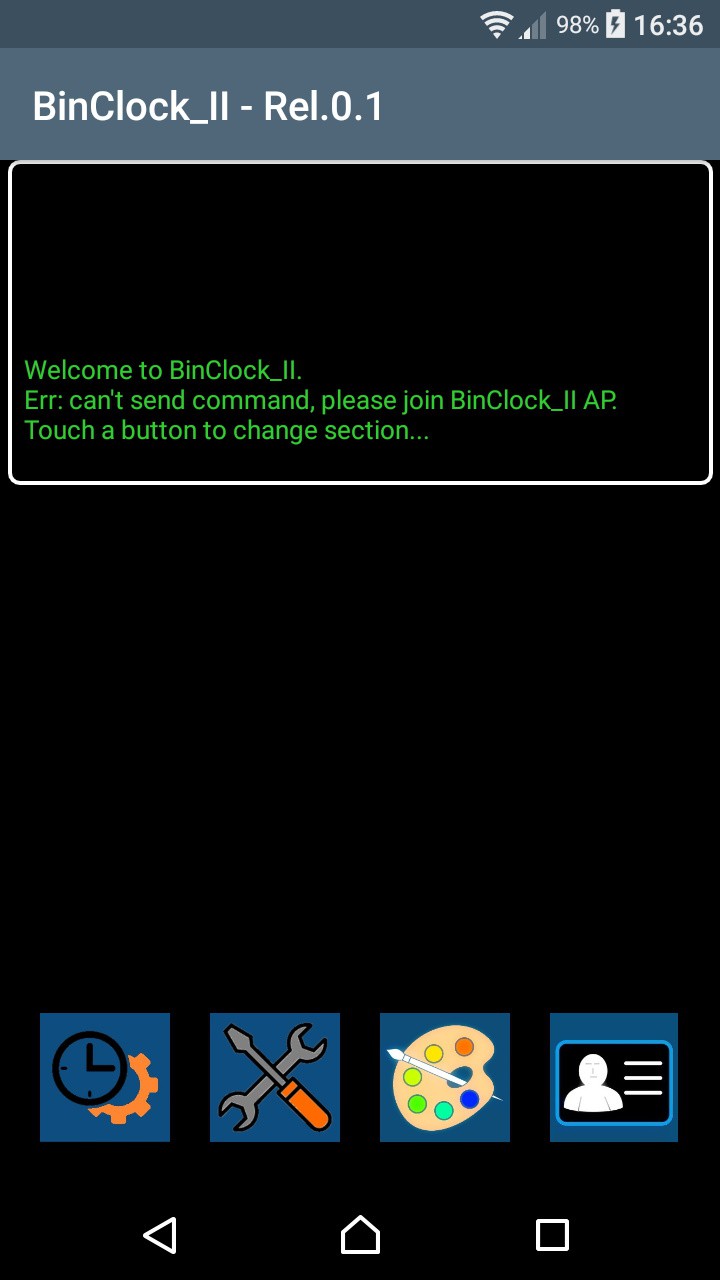
At the top there is the message window, where we read the various operations and the answers coming from the clock. Note the error highlighted in the second line of messages: this is shown if you launch the App without first being connected to the AP BinClock_II. At the bottom we find the buttons that send us to the four sections for the various settings. Read the previous part, where the use of each input is explained in detail. Let's start by clicking the first icon on the left and go to the Real-Time-Clock section:
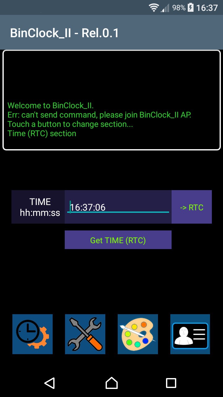
Here is a little trick that doesn't exist in the PC app. If you hold down the time entry field for a long time, it is automatically filled with the current smartphone time. You do it quicker than to insert it by hand! Now click the second icon on the left and the new section (Hardware) appears on the screen:
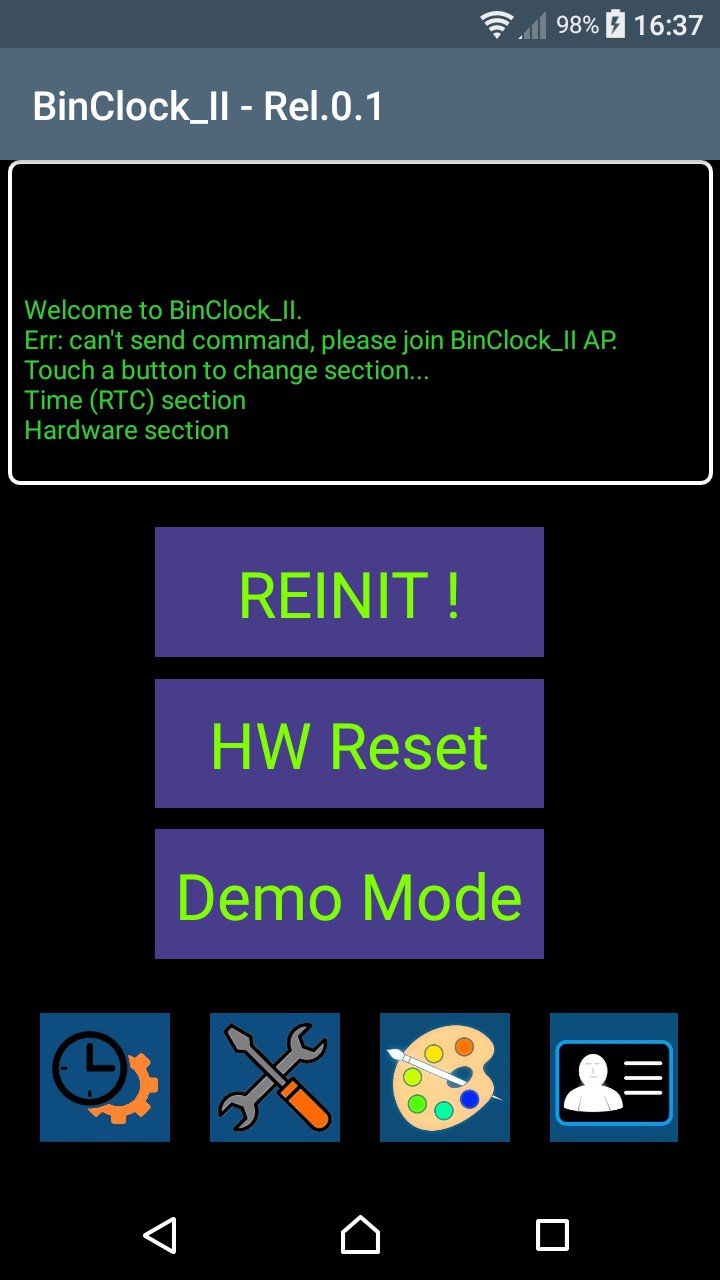
Here there are no differences from the PC, the controls are identical. Now click the third button from the left and here is the new section (Palette & LedMap):
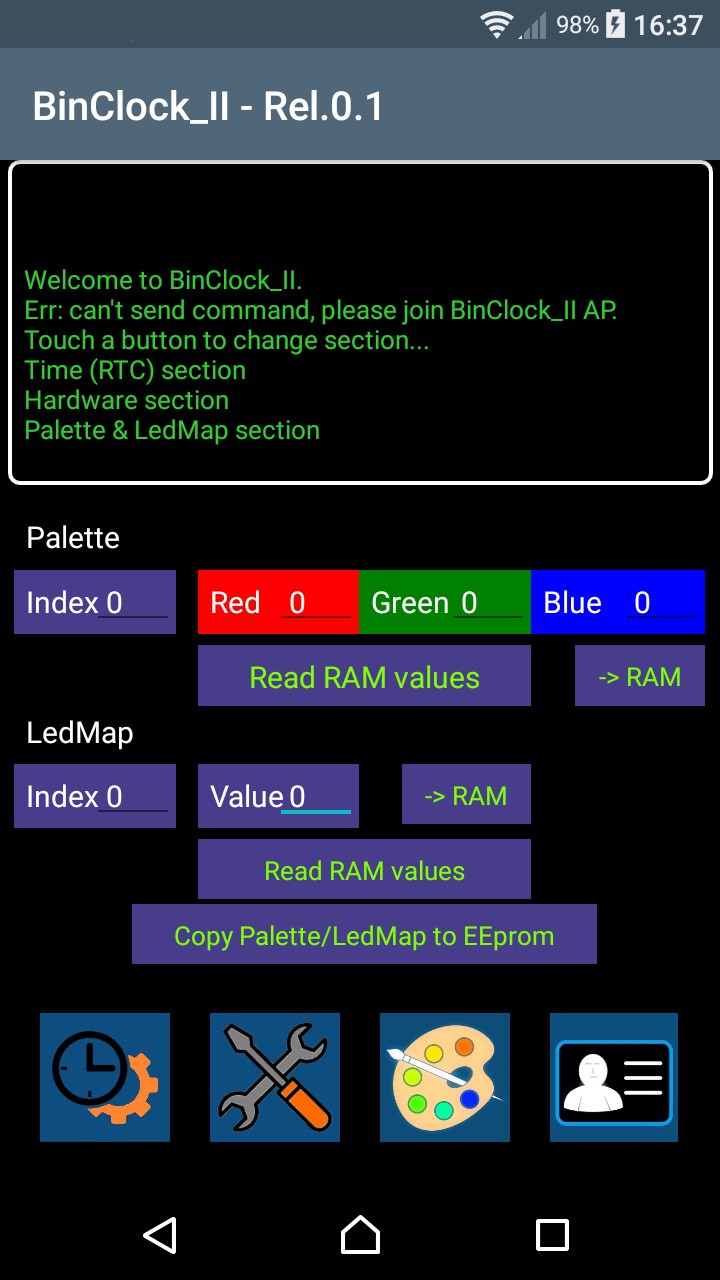
Here the sections of Palette and LedMap are grouped. Compared to the PC version it is easier to enter data, because some input errors are corrected. For example, while in the app on a PC it is mandatory to write 040 to give the value 40, here it is enough to write 40. There is however a control of the inputs to avoid "impossible" values. Finally, by clicking the last button from the left, we go to the new section (Credentials):
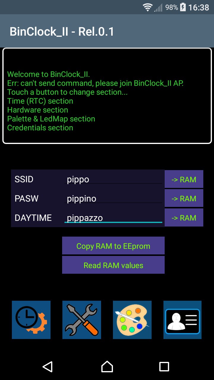
Here there is no verification on the data entered, so put the right ones in!
Before launching the App, you need to do two things:
1) on the watch, press and hold the "service-pin" button for 5 seconds. Doing so activates the ESP8266 in AP (Access Point) mode with the SSID BinClock_II and password 88888888 (eight times eight). When the watch is in this condition, it can be controlled with the App. To warn us that we are in this condition, the blue LED next to the service-pin button lights up twice per second, instead of once a minute. This condition ends automatically after 5 minutes without a connection being made (or with a hard reset).
2) on the smartphone you have to access the WiFi settings and connect to the Access Point BinClock_II and provide the password. The phone will tell you that you cannot go to the Internet and rightly so, because you are connected to the watch, which is not connected to the Internet.
3) launch the App and have fun. Keep in mind that a couple of commands (HW Reset and REINIT) cause the reset of the micro and consequently the shutdown of the Access Point. For all the rest, what was said previously applies.
Conclusions and annexes
That's all. In the “files” section you will find, zipped together, both the .bin file to program the micro, and the .apk for the smartphone (Android). The binclock2_210327.zip file has a password which is: eficara. Before any unzip / exec operation on files downloaded from the Internet, check the SHA-1 code to be sure that the file is intact and not manipulated by others. In this case the hash must be: 0875DEECF534821343946D267F9EA33386BF24B0
Disclaimer :
I remind you that I take no responsibility for errors / mistakes or for any problems that
may arise with the download and / or installation of the material made available. It is material of a hobby nature and made available free of charge, so you, by using it, take full responsibility. I am not an expert on "legal terms", but I hope the concept is clear enough.