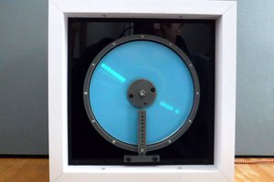
This project makes use of Photo Luminescence using paper layered with Strontium Aluminate which has a green glow although different mixes can result in different colours and persistence.
Once charged, light from the paper will continue to be emitted after the charging light has been remove. The charging light in this case comes from UVA LEDs.
The light emitted after charging is initially very bright but quickly decays to a lower intensity becoming further deminished over time, this persistance can last for several hours. if the paper is exposed multiple times in relatively quick succession then multiple ghost images will be present. Therefore, to minimise this effect a delay is applied between successive exposures.
Consequently, this project is best viewed in a low light environment.
UV LED's are used to illuminate luminous paper but require some means of moving the LED's over the paper to create the numbers.
This is achieved by using a single (x axis), leadscrew.
The leadscrew is directly driven by a DC motor which can rotate clockwise and anti-clockwise.
Fitted to the leadscrew is an arm and to this 8 LED's are attached to form one column.
Although 8 LED's are available to form characters, only 5 will be used at this time to retain compatibility with the Microbit display.
As the leadscrew rotates the arm moves across the paper pausing momentarily to turn on the required number of LED's this continues until all the required numbers are displayed.
The leadscrew supports the LED arm and is 3D printed.
Each character is stored as an array element in a string of five 2 character decimal numbers, one number per column
When converted to binary the character is formed in a 5 x 5 matrix
Each array element from 0 to 9 corresponds to the numbers 0 to 9
0 = "1417211714" ... 9 = "0221130502"
All elements are connected to the Robotics Board, this can control 4 motors and 8 servos and allows connection to MicroBit pins.
In this application only one motor will be used which will drive the leadscrew.
No servos will be used but instead these 8 outputs will be utilised to control 8 UV LED's
Hall sensors will be connected to the MicroBit on P1 and P2 for endstop detection. Both active low.
Buffer enable (active low), is on P8
Time setting is enabled and disabled with a switch connected to P0.
Button A is used to set the Hours and this is connected to an external switch connected to P5
Button B is used to set the Minutes and this is connected to an external switch connected to P11.
Some soldering is required for the IC buffer, Hall sensor circuits, pin headers on Microbit and LED board.
Short 100mm jumpers are used to connect the RTC and Micro USB breakout.
A combination of 185mm jumpers and custom leads are made for the longer cables runs to the Buffer Board, LED's, Hall sensors, switches and motor.
The Hall effect sensors are omnipolar, meaning they will respond to either magnetic polarity.
They are open collector output, meaning that a pull up resistor is required, in this case 2K2R.
The 100nF capacitor is for noise decoupling.
For ease of insertion or removal the sensor is screw fitted to a 3pin terminal block whilst the resistor, capacitor and flying leads are soldered to the pins.
When powered and in the abscence of a magnetic field the output is High when a magnetic field is detected the output goes Low.
Ensure that is sufficient cable length from the right hand motor support to the Robotics board.
The UV LED's are not driven directly by the microcontroller.
We will make use of the Robotics board which has 8 servo outputs allowing us to control each LED individually with PWM.
But due to low drive capability a buffer IC rated up to 7.8mA per output is used to drive the LED's from a 5V supply.
The IC is a Non Inverting Octal Buffer with TriState outputs. In this case the IC is mounted on a piece of stripboard in a IC socket.
Right angle pin headers are used to make the connections for inputs, outputs and power.
... Read more »
 Tinkers Projects
 Sander van de Bor