 JP Gleyzes
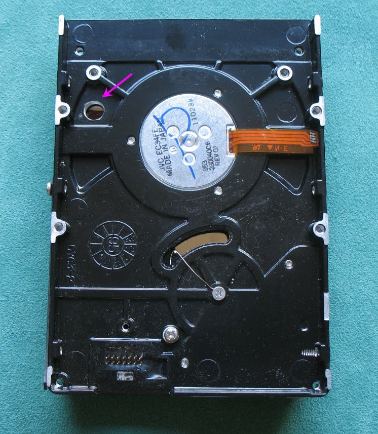
RPR220 phototransistor is soldered on the PCB and its led focusses IR beam on the bottom platter of the disk. A hole is drilled in the disk enclosure for that. A dark spot is painted on the disk to be detected easily by the sensor.
It is highly recommended to position the PCB on the disk before soldering the RPR220 sensor. Doing so will allow you to use the 4 pins holes to mark the disk enclosure and so to easily position the hole on the enclosure.
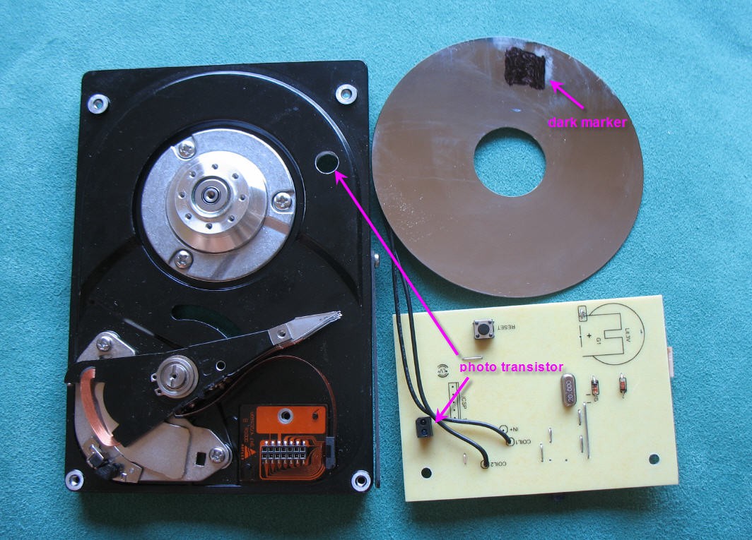
Idealy the phototransistor should fly at 6mm of the dark mark. Fine tune the pins lenghts if necessary before soldering.
However it is not that critical, a calibration procedure exists and will be described later. Provided that the phototransistor sees the dark mark, everything will be fine!
Similarly the dark mark do not has to be recise at all. Paint it manually on the disk using a permament marker.
You can remove the original PCB, but take care to unsolder the HHD motor ribbon connector. It will be reuse on our new PCB.
Do not damage the motor ribbon!
Discussions
Become a Hackaday.io Member
Create an account to leave a comment. Already have an account? Log In.