Emilio P.G. Ficara
Oscilloscope as display: “Oscillogio”
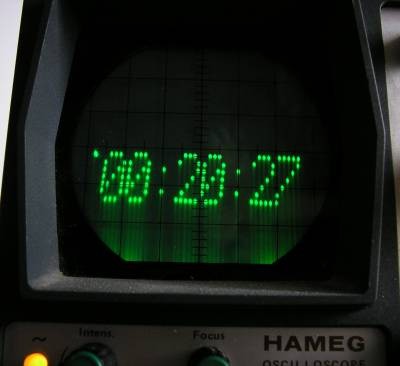
This is a digital clock that uses a single channel oscilloscope as display. Only the ‘Y’ axis modulation is used, so every old (and tired) oscilloscope can be used (note: it will not work with digital oscilloscopes).
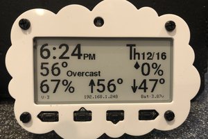
How the time will be presented:
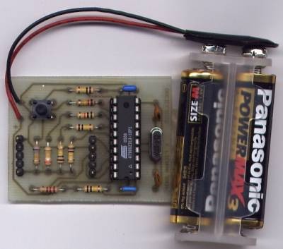
The circuit realized on single side PCB:
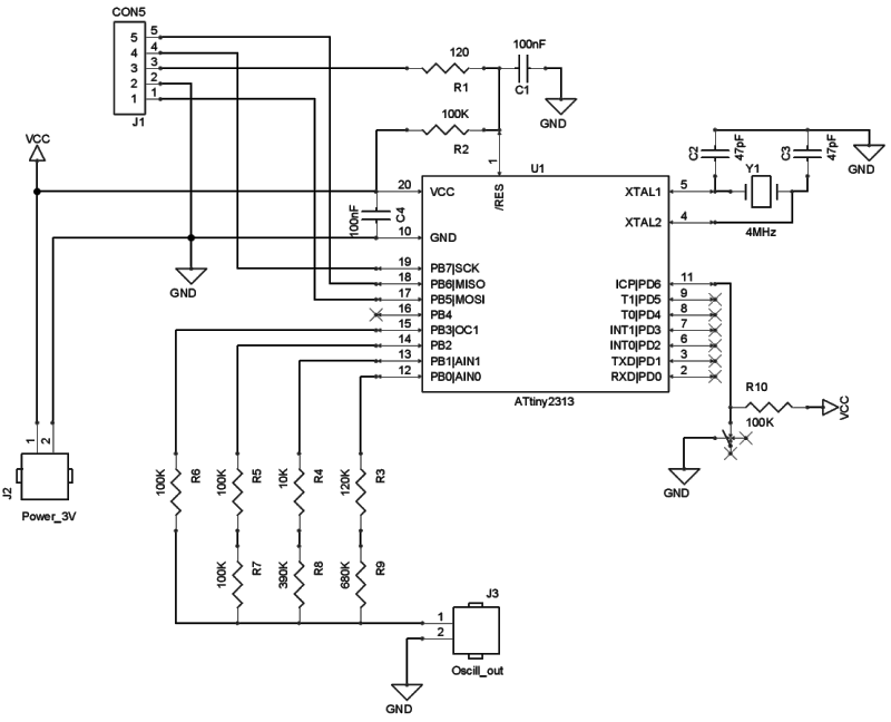
This project was published (by me, of course !) on the 2007 June issue of italian magazine “CQ Elettronica”. The circuit is based on popular ATtiny2313 or AT90S2313 microcontroller. If you plan to use the first one (the ATtiny2313) please remember to program the fuses for external xtal oscillator. In the “files” section you can find the file ef126-oscillogio.zip (password: eficara) that contains also the batch files to program the memory and the fuses of the microcontroller using the "SP12" free tool.
This is the schematic (in the zip you will find it also in PDF format):
And finally the contents of file ef126-oscillogio.zip:
main.c – the C source file
schema.pdf – the electric schematic in PDF format
stampato.pdf – the PCB layout in 1:1 scale
lista_materiali.txt – the bill of materials
montaggio.jpg – the components mounting map
ckscope.hex – the HEX file to burn the micro
tinySetClock.bat – the batch file for micro’s fuses programming
wrProg.bat – the batch file for micro’s memory programming
Oscilloscope as display: "Scrolling text"
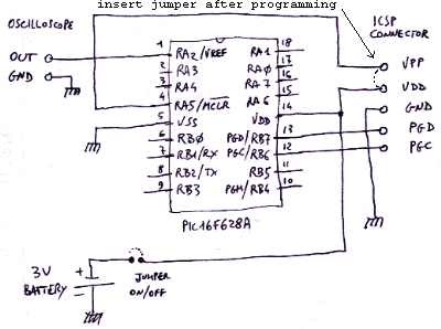
Scrolling text on oscilloscope, built with only one component: the Microchip PIC16F628A. The characters to be displayed are stored in EEPROM (ascii codes from 0x20 to 0x5f so numbers, capital letters and special characters). The first Eeprom location with 0xFF value is considered as end of text. The last Eeprom location (addr 0x7F) contains the scrolling speed in 20mS steps. The configuration word for this application (address 0x2007) is 0x3F34. After programming the micro via the ICSP connector, place a jumper between the pins VDD and VPP (reset input tied to Vdd). The oscilloscope will be set for 2mS/div on X axis and 1V/div on Y axis. One full screen contains 10 characters.
In the “files” section you will find the file ef140-scrolling-text.zip (password: eficara) that contains the .hex file to program the micro and the C source.
Note: When programming the micro, verify that the configuration word is 0x3F34 and remember that you MUST write some character to earom memory; if in doubt, try with this data starting from earom address 0x00:
0x49 0x54 0x20 0x57 0x4F 0x52 0x4B 0x53 0x20 0x41 0x54 0x20 0x45 0x4E 0x44 0xFF
then write at address 0x7F: 0x0A (that’s decimal 10 * 20 mS scrolling speed).
If the scrolling speed is too fast, increment the number in location 0x7F.
Maybe trigger level adjustment will be needed on the oscilloscope, in order to synchronize the scrolling text. The text field is preceded by a single sync pulse. Adjust the trigger level to make the text field stable. In many oscilloscopes, this will be done automatically, but some old one (like mine) will require a manual level adjust. Note that this circuit DOESN’T WORK with digital oscilloscopes, due to the dots visualization method.
The full schematic:
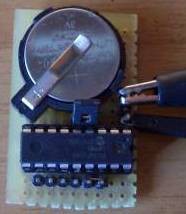
The prototype:
That's all (for now)...
 James Fossey
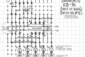
 sbi.gaijin
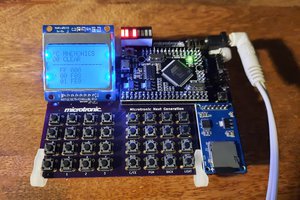
 Michael Wessel