 Collin Matthews
General Stuff:
The circuit design was fairly simple, given the electronic shortage, there was not a ton of options as far as IC chips went. I used a fairly common Lipo charging IC, along with a TI amplifier chip good for 120mW per channel (Way more then I needed, but it led to a simpler design vs op-amps etc.)
I then scaled the resistance down for a typical Baxandall tone control from 500k to ~50k impedance, since the source is the power amplifier output which is very low, and the lowered resistance would reduce any noise. Although given a 1V/V amplification scheme and the large initial voltage, noise is not really a concern here.
Worth noting the THD was also considered, the TI chip quotes 0.02%, but in practice is worse given my low load. An op-amp could do much better, but again as a tube guitar amplifier is the sound source, the small amount of THD added here is insignificant.
|
|
 |

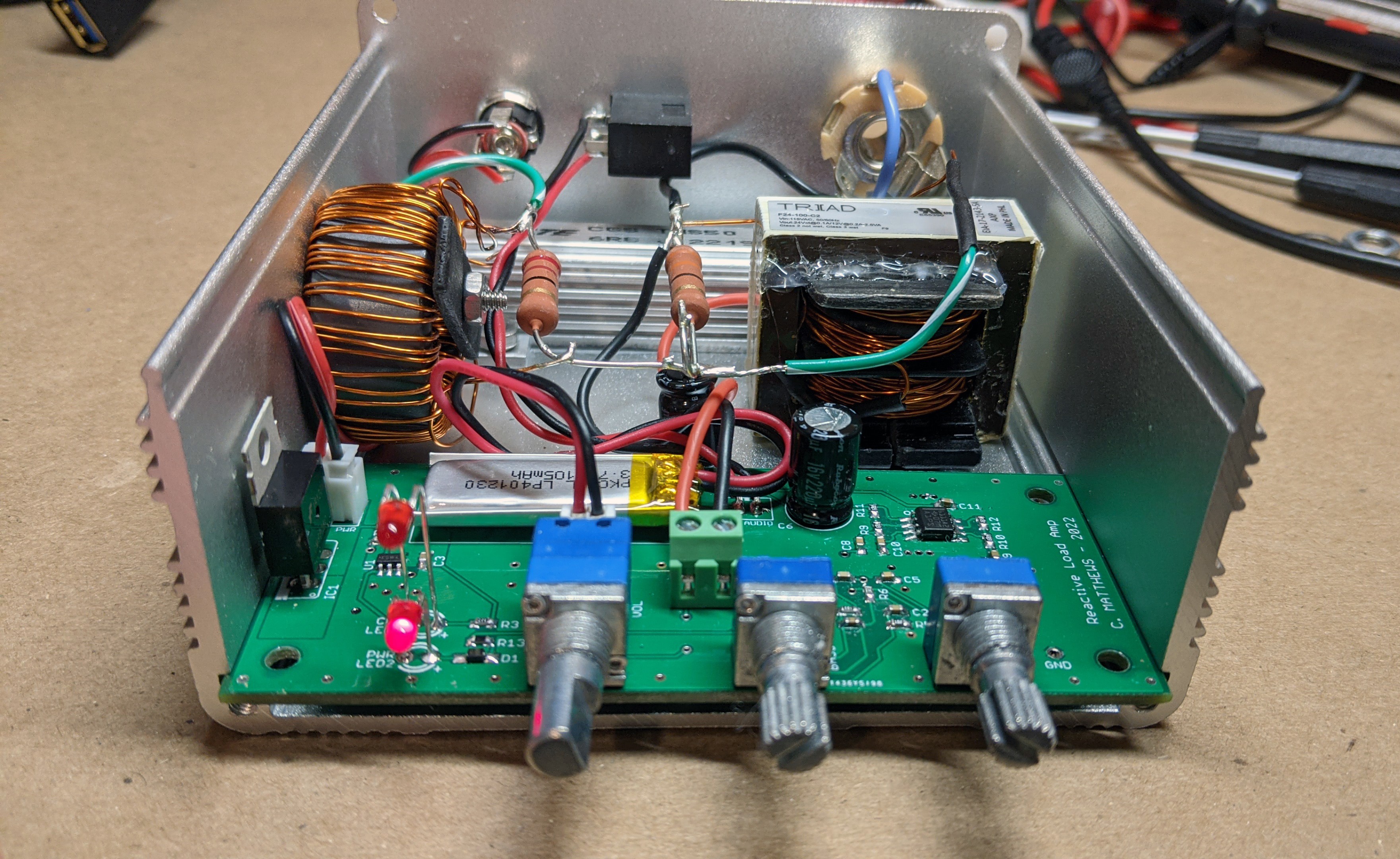
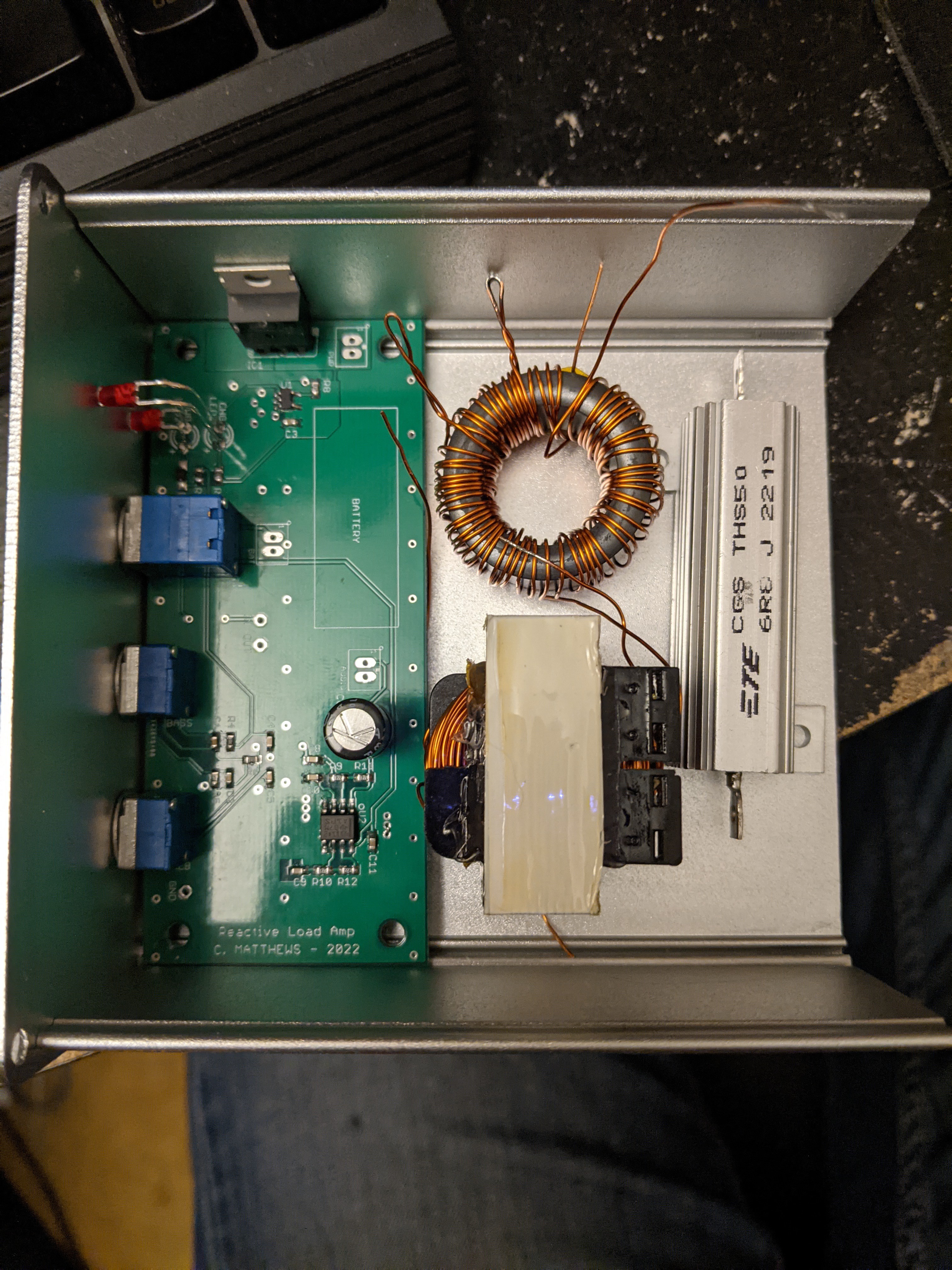
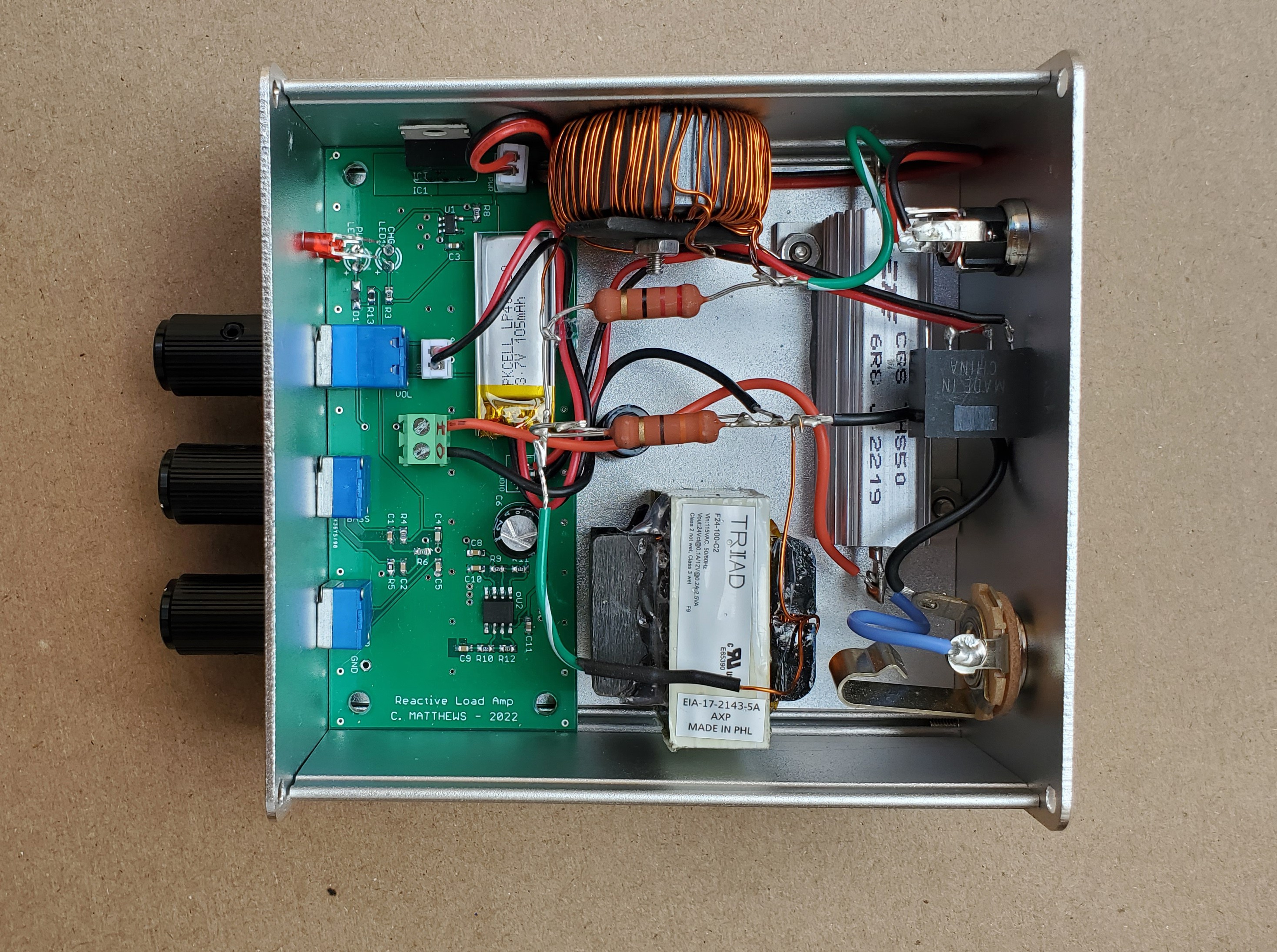
I ordered a cheap aluminum box off Amazon that had slots for a circuit board to slide into it. I used 40mm of the 100mm length for the board, and figured the rest would be mounting locations for a power resistor and inductors etc.
Being aluminum, it will act as a heatsink, so no internal fan is needed.
Also worth noting, Ideally this would have been charged via USB, but I lack the tools to make a clean looking cutout for a USB port. So i instead opted to just power it from 9-12V DC. Future mods may include 2 power jacks, one for normal 9-12V, one wired to support the typical -9V pedal power used for most pedal boards (-9V due to center being negative, as opposed to most general devices and power supplies being center positive.
Simulation Results:
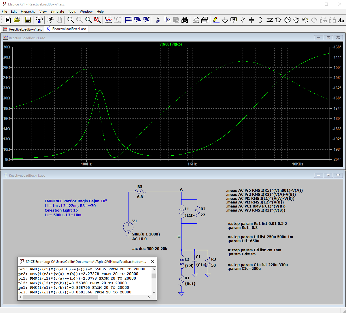
Ran a simulation of approximate component values I was planning on using. The circuit idea here is from here. It is worth noting this site has a lot of good explanation around guitar amps and tube amps. If you want to build your own, it is a nice reference. The first trough is a high impedance designed to mimic the resonant point of the mechanical speaker, and the high frequency roll-off is again mimicking the increasing impedance to higher frequency due to the inductance of the speaker coil and mechanics.
Inductor Design:
Modern inductors are designed for high frequency power supplies. It is harder to buy an off the shelf inductor designed for low frequency like audio that can handle large currents on the order of a few amps.
From my simulation, I could tell for a 10W load, I needed to handle peaks of 1.5A at least... In reality more was probably needed, but I also figure if my inductor saturates at higher power levels, that might just be something I live with here. Unlike a power supply, saturation here would just lead to more THD and not catastrophic failures.
Here is a good online calculator I found for this, that makes things very easy due to the large amount of unit options, there is less messing around in excel or on paper to balance everything out
here
There are 2 options for low frequency inductors:
- Historically accurate iron core inductor (Basically a transformer with a single winding since Iron cores are much better for lower frequency inductors.)
- Find a large low permeability torrid that can handle enough windings to meet the inductance needed (25mH in this case is my worst one).
I initially chose to go with option 2 since it seemed easier, and my inductance was low enough it can be achieved without thousands of turns of wire (Or so I thought). I then spent way to long searching Digikey and manufacturer web pages to find something that was not huge, but met the current and reasonable amount of turns requirements. Turns out the 500uH inductor was doable with a modest torrid. The 25mH inductor on the other hand really needed to be silicon steel like a transformer or choke design. There was no readily available ferrite that met my needs.
The 500uH Inductor:
I bought a 30mm torrid and wound #24 magnetic wire around it, I wound something like 60 turns with taps at 45, 55, and 60 because I was unsure exactly how much inductance I wanted. I also knew based on my calculations the core might realistically saturate below my goal, and I could trade off less inductance for more current handling if needed.
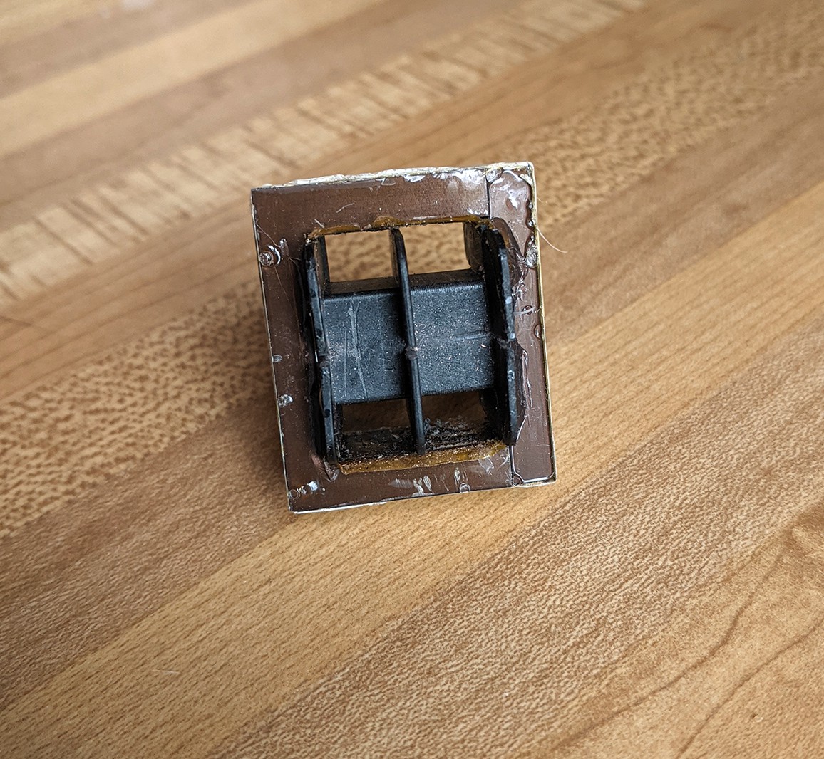
The 25mH Inductor:
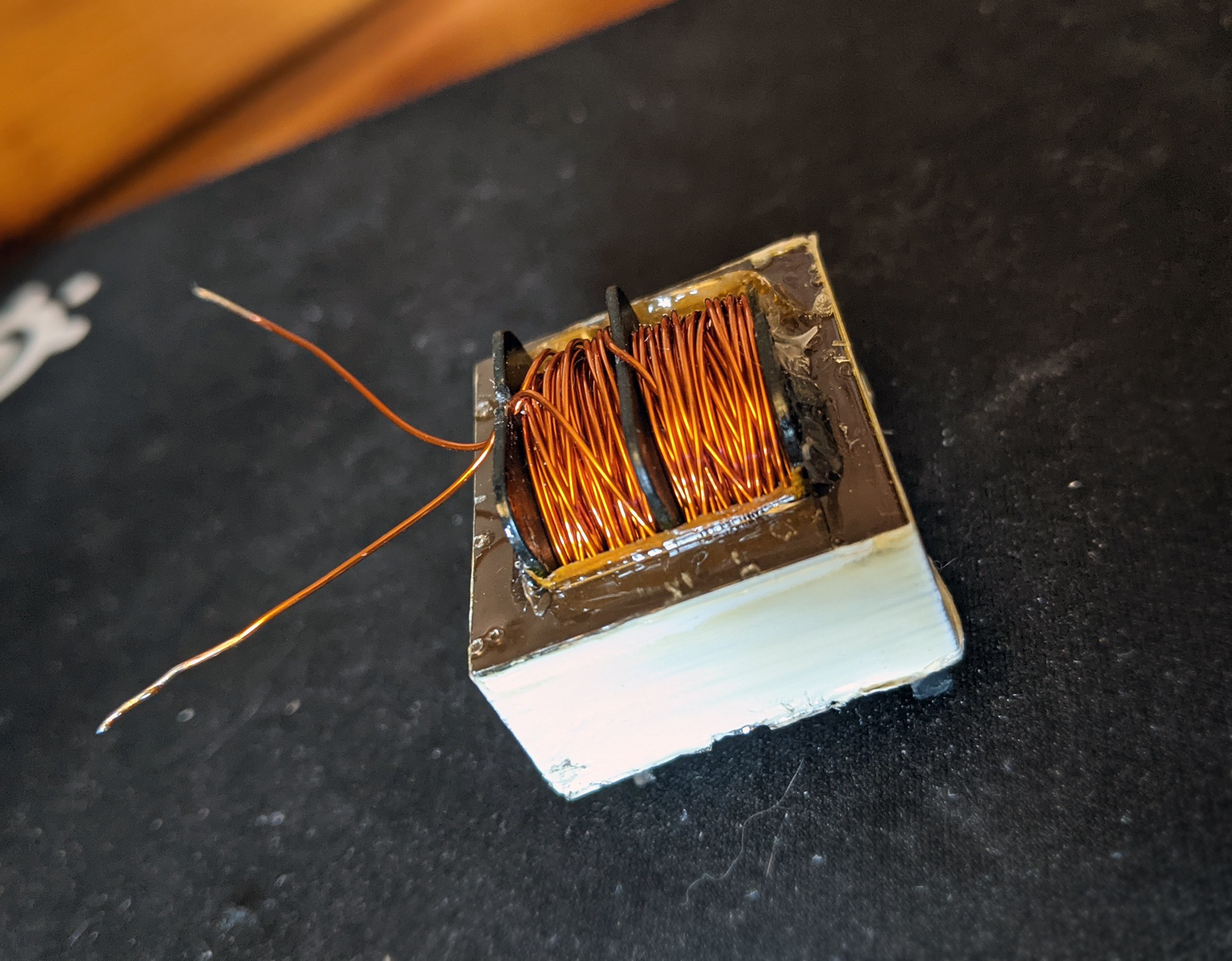
After not finding the right torrid available, I decided to buy a small 2VA transformer that looked easy to rip the windings out of, and based on some calculations though I could rewind it with ~50 turns of wire to get the needed inductance. It would be a pain, but cheap and quickly available. I used a hack saw to cut to the bobbin on both sides, and a need noes pliers to grab bunches of wire and pull it out. Surprisingly it only took 20 minutes to remove all the copper and clean it up.
Unfortunately after measuring a few loops and back calculating the AL value, I found the assumptions I had made about relative permeability of the core was off, and I needed closer to 150 turns to get my inductance. That would also lead to a larger copper loss / internal resistance... At this point I looked at some speaker models and found that I could get away with closer to 10uH and still model a realistic 8in guitar speaker. Which one of my tube amps has.
I then used again #24 magnetic wire, and took the painful process of winding two sets of coils on the bobbin with as many turns as I could fit. Since it was challenging to wind, the winding was not clean and thus a fair amount of space for copper was wasted, but I eventually ended up with 7mH (According to my cheap LRC meter). Not great, but I was going to work.
 |
 |
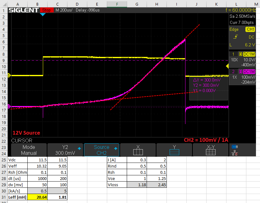
Saturation Testing:
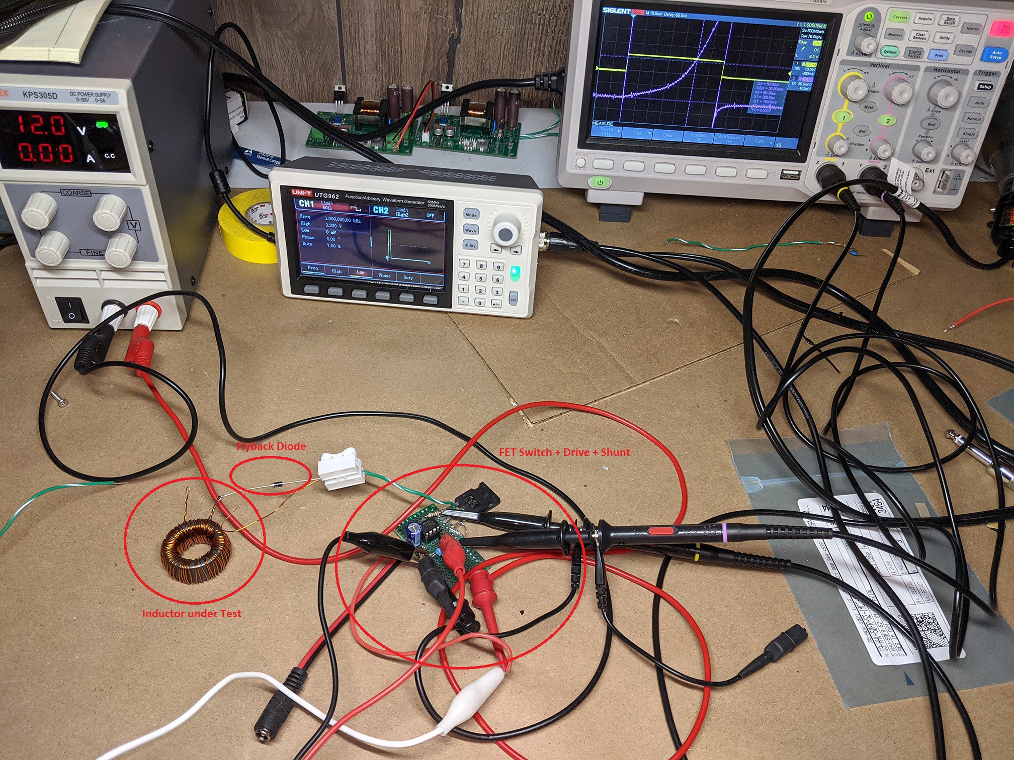
Testing the current handling abilities of inductors can be done with a fairly crude setup. You just need some form of an electric switch driven from a signal generator, a shunt resistor and an oscilloscope. You are also going to want some sort of diode to handle the inductor current when the switch is turned off, otherwise the energy generated by the inductor current has no path and you will get a voltage spike on your switch until it breaks down.
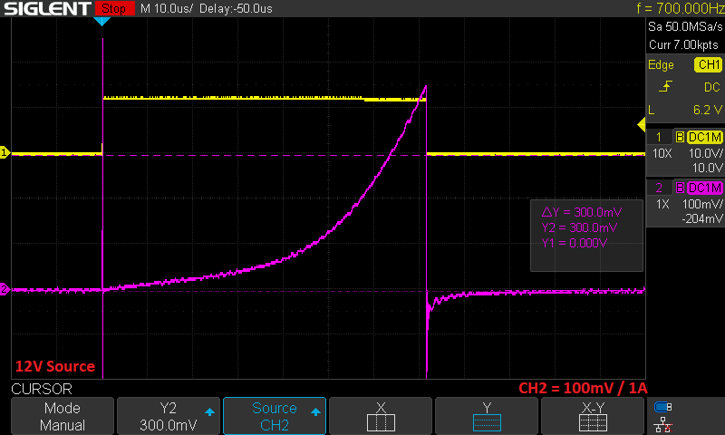
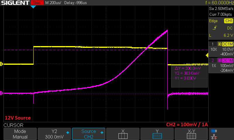
Unfortunately during this testing, I realized for larger inductors with significant internal resistance, my LRC meter might not be as accurate as I assumed. I was surprised by the low saturation current on the 25mH inductor I wound. I was also surprised how I had to add more windings then expected from calculations.
Back calculating the inductance showed me why, based on this data it appears that my inductor is not 7mH but instead closer to 20mH, which would also explain the lower saturation limit, since increasing inductance on a given core will reduce the saturation point.
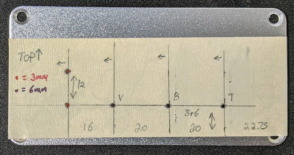
Fabrication:
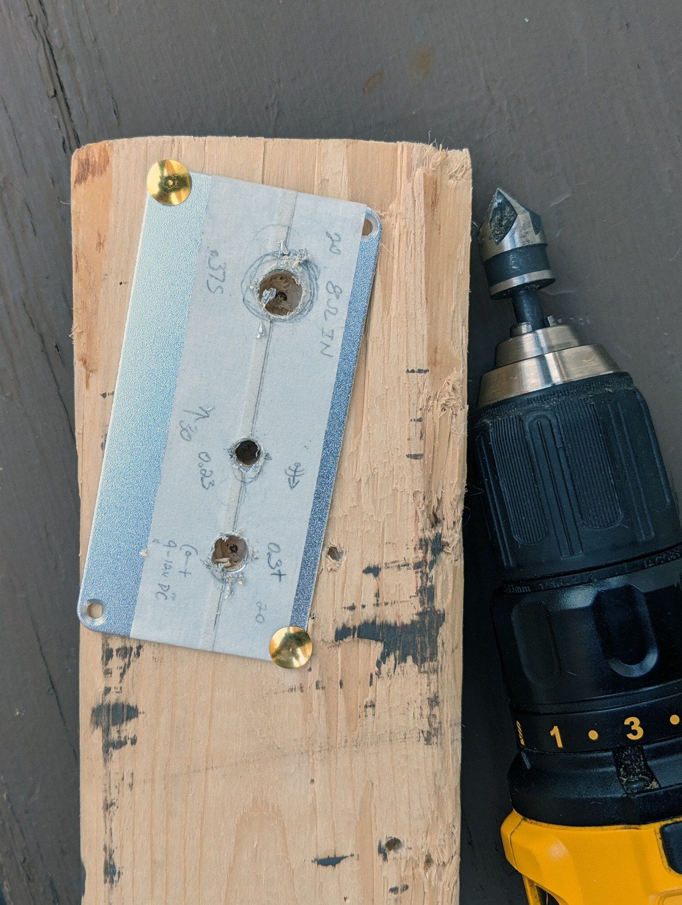
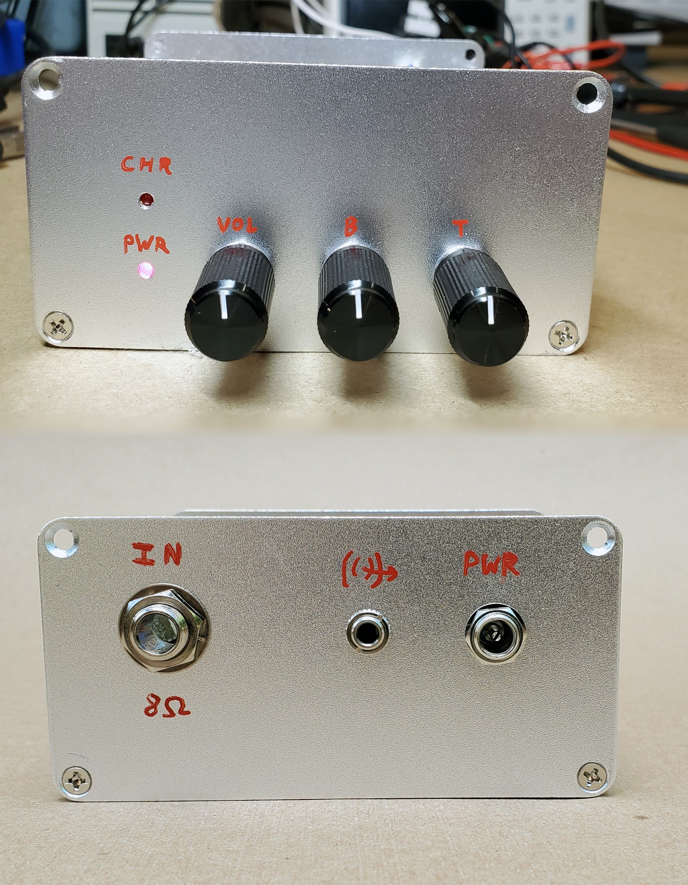
Marked the holes with respect to the PCB layout and just what seemed aesthetically pleasing on the rear panel.
 |
 |
 |
 |
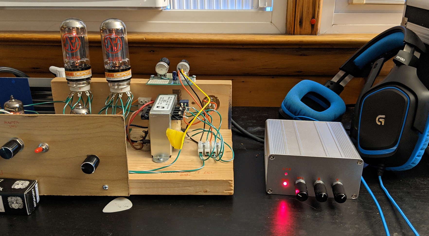
Final Results:
Future Enhancement Opportunities:
- There currently is no over voltage/polarity protection on the power jack, a simple diode would fix this, as well as eat some of the excess incoming voltage. Again USB power would fix this concern.
- Over voltage protection on the headphone amp input. If you were to plug this into a larger amplifier (50W) cranked up, the audio signal going to the TI amplifier chip would be outside of the acceptable max range. Although it is current limited and AC coupled, so I'm not sure actual damage would be caused. This could easily be achieved with diodes on the audio line entering the TI chip to both supply lines.
- Additional tone shaping circuit, maybe utilizing the unused 2nd amplifier channel. While this box emulates a speaker load, it does not emulate the sound.
- Additional dynamic range above the 4.2V offered by the battery would be nice for less sensitive headphones, I'm finding I'm often driving the amplifier near the rails.