Jithin Sanal
Voice Controlled Door Lock: An Overview
Hey, everyone! Welcome back. In this video, we'll make an Alexa-controlled door locking system that lets us lock and unlock a door with our voices. This lock is easy to design, make, install, and use. Not only do they make your home safer and more convenient, but they also make it easier to install and use locks in general.
Let's get started! So let's begin with the circuit! I drew the circuit and made the PCB with the help of the Altium designer. Here we are in Altium designer. Here, I'll be using a Solenoid door lock that works on 12 V, so I'll connect a 12 V DC adapter. A 7805 regulator is linked to the power source. The 7805 is a 5V regulator that can turn a 7-32V input voltage into a steady 5V DC supply. There are LEDs at different places to help you figure out what's wrong.
Alexa Door Lock Circuit
There are two switches here. One is a Relay that is turned on by a transistor BC547, whose base is connected to Digital Pin 3, and then there is a MOSFET that is connected to digital pin 5 of the Arduino. Here, you should also see a buzzer that this transistor turns on and off. The digital pin 6 of the Arduino is linked to this transistor.
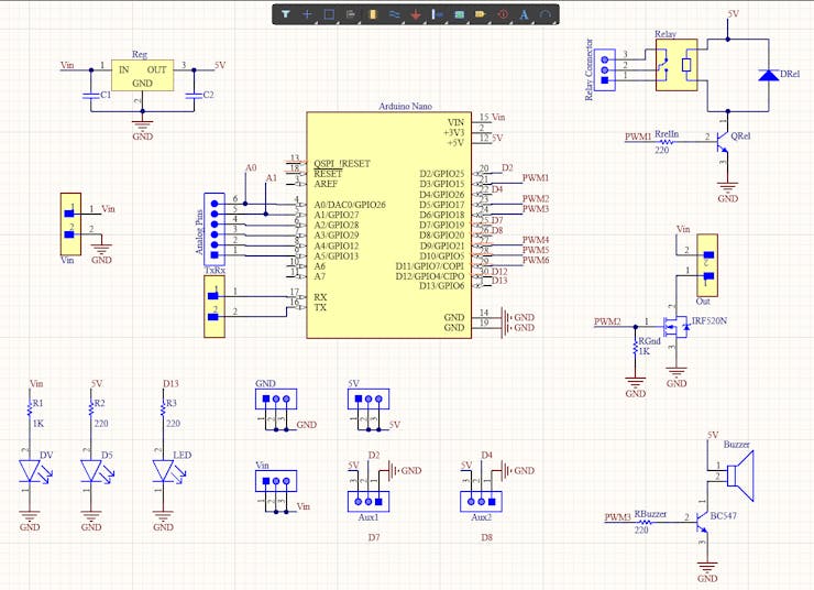
You can connect the lock to either the MOSFET or the Relay, both of which can be programmed to turn on and off. I decide to connect the Lock to the MOSFET so that I can use the relay to connect something else, like a light bulb. You can connect extra things, like a lamp or a motor, to the other switch to open the door, like a motor or a lamp.
This is just my idea. As I said before, I'll put the plans in the description so you can redesign the whole thing, change it, and then make your own version. Or you can make it like my version. Before you do anything else, you should try it out on a breadboard. Once you have the output, you can either use it as is or use it to make your PCB.
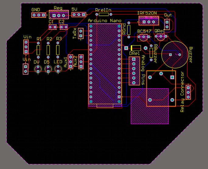
I made the decision to go with the PCB. I made a PCB layout where you can easily mount your Arduino Nano RP 2040, relays, MOSFETs, and other components. This way, you don't have to use wires and cables that are all over the place. And making your own PCBs for your project is cool, right? The board is small and easy to carry. Depending on the Solenoid Lock voltage, it can be powered by a 9V battery or a 9–12 V power adapter.
Getting the PCBs Done
I ordered PCB from PCBWay. PCBWay is a PCB manufacturer specializing in PCB prototyping, low-volume production, and neat and tidy PCB assembly. If you are interested in making your own PCBs for your project, check out the link below. You can get a 5-dollar discount when you sign up using the link below and get an additional 5-dollar discount at the checkout by providing the coupon code PCBWayLab.
To order your PCB from PCBWay, go to the PCBWay website and fill in the basic board details in the instant order form. From there you will be directed to a form where you can provide more elaborate board details. Update your board information in the PCB specification screen. On the next screen, you should be able to upload your Gerber file and submit it for review. Once the review is completed, all that is left is to add to the cart, make payment, and wait for your PCBs to arrive.
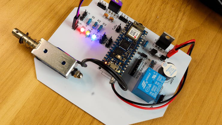
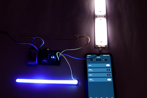
Once you get all the components and the PCB, it’s time for you to solder them together. Solder all the components onto the board and make sure to check the polarity of the components. After soldering the PCB looks like this.
Using the Arduino Cloud to program a door lock
Let's talk about the software now. Here, I'll use Arduino IoT Cloud to write code for the board. Here, we've made a new project or "thing" for our voice door lock and made a switching variable that works with Alexa devices. Then, an Arduino Nano RP2040 Board was added.
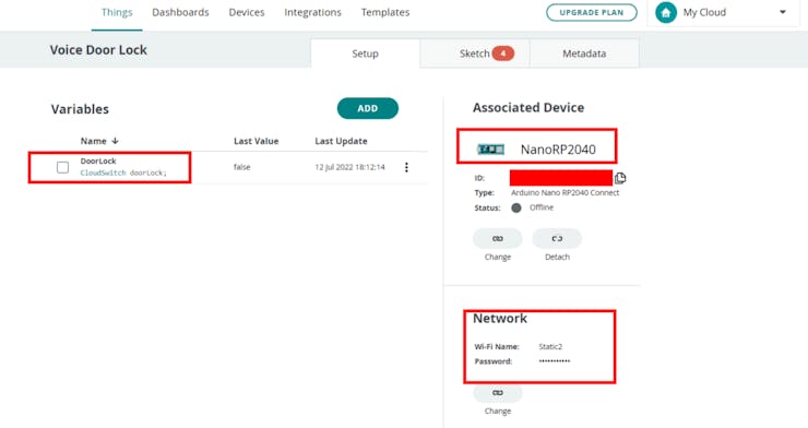
This page will show you everything you need to know about your project. Here, you'll find all the information about your project, such as the attached board, variables, network, sketch, etc....
Read more »