 Evan
EvanApple sold millions of iPads the year they were introduced. These devices were capable of browsing the web, watching movies, and playing games, with up to 10 hours of battery life and an intuitive touchscreen display. Apple essentially defined what a tablet should look like, and competitors are still playing catch-up.
However, all the original iPads are many years out of date. While some apps still work, and some can be made to work by jailbreaking the device, due to a lack of software support by Apple, these tablets are unable to do many of the things they used to be capable of.
The hardware isn't terrible, though! The iPad has a nice touchscreen, an okay LCD, a beefy battery, and enough buttons and ports to make it still useful as a computing device.
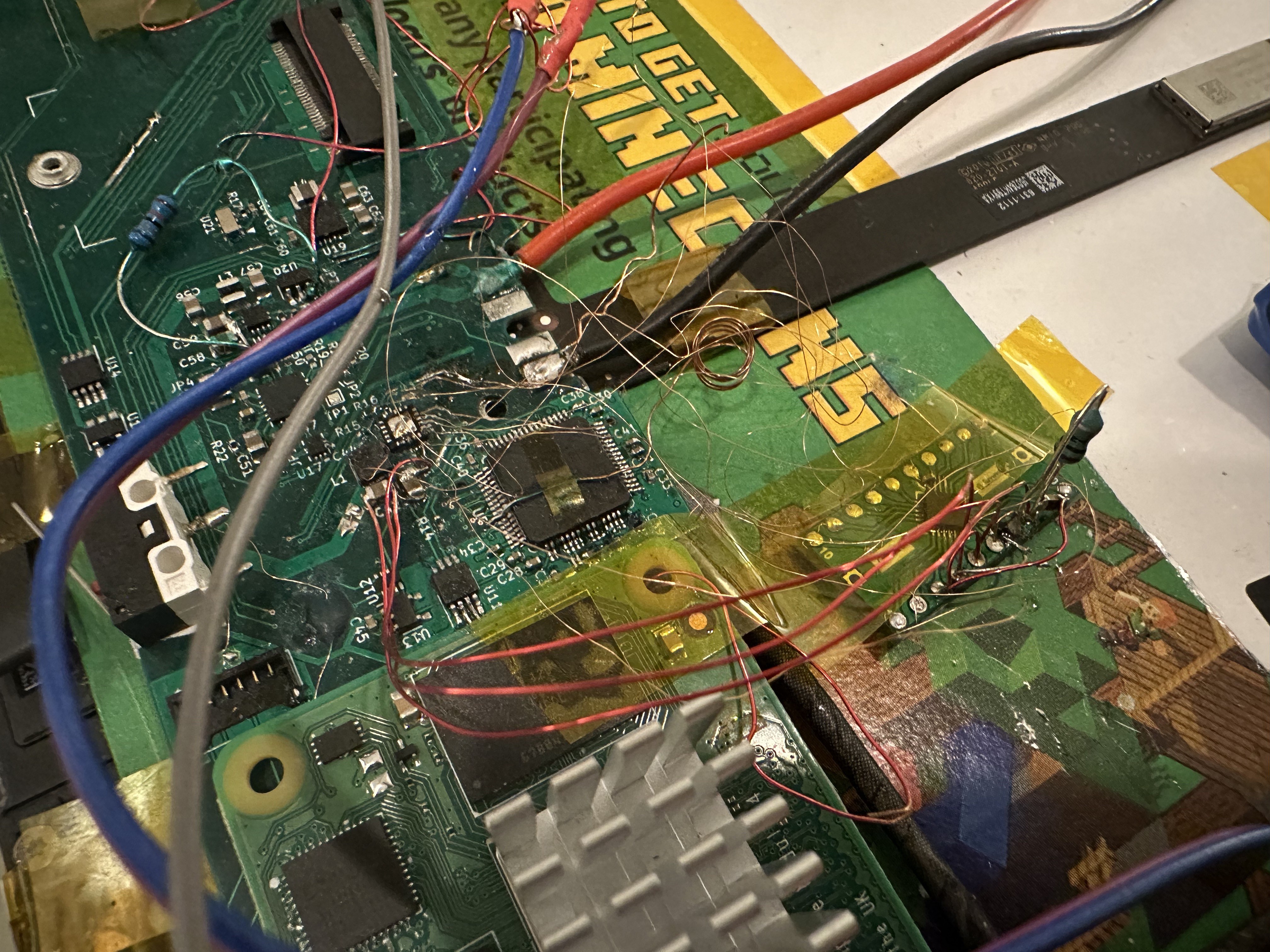
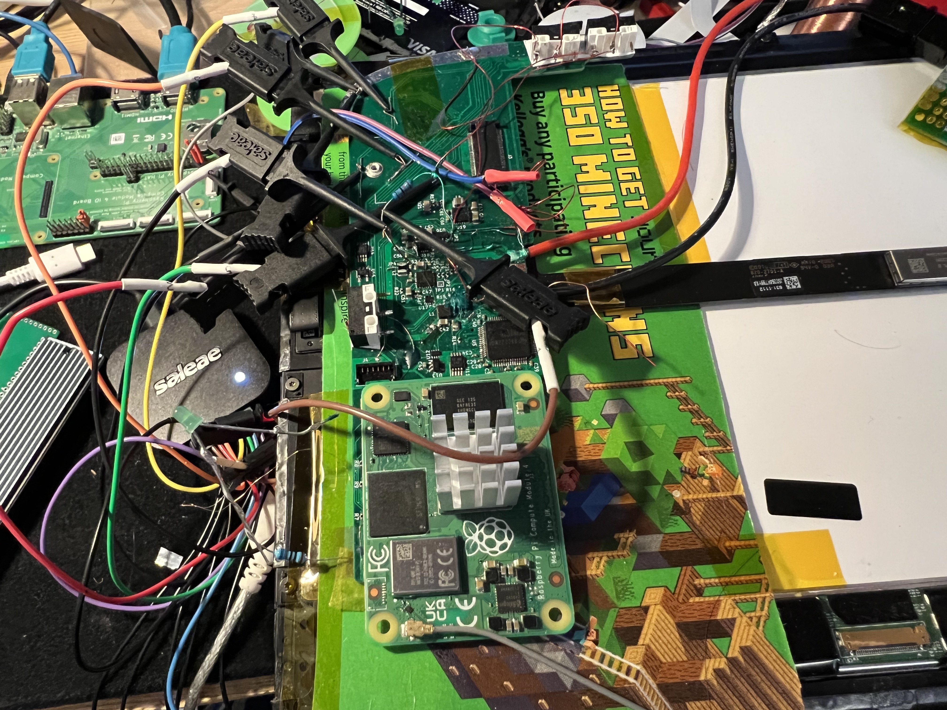
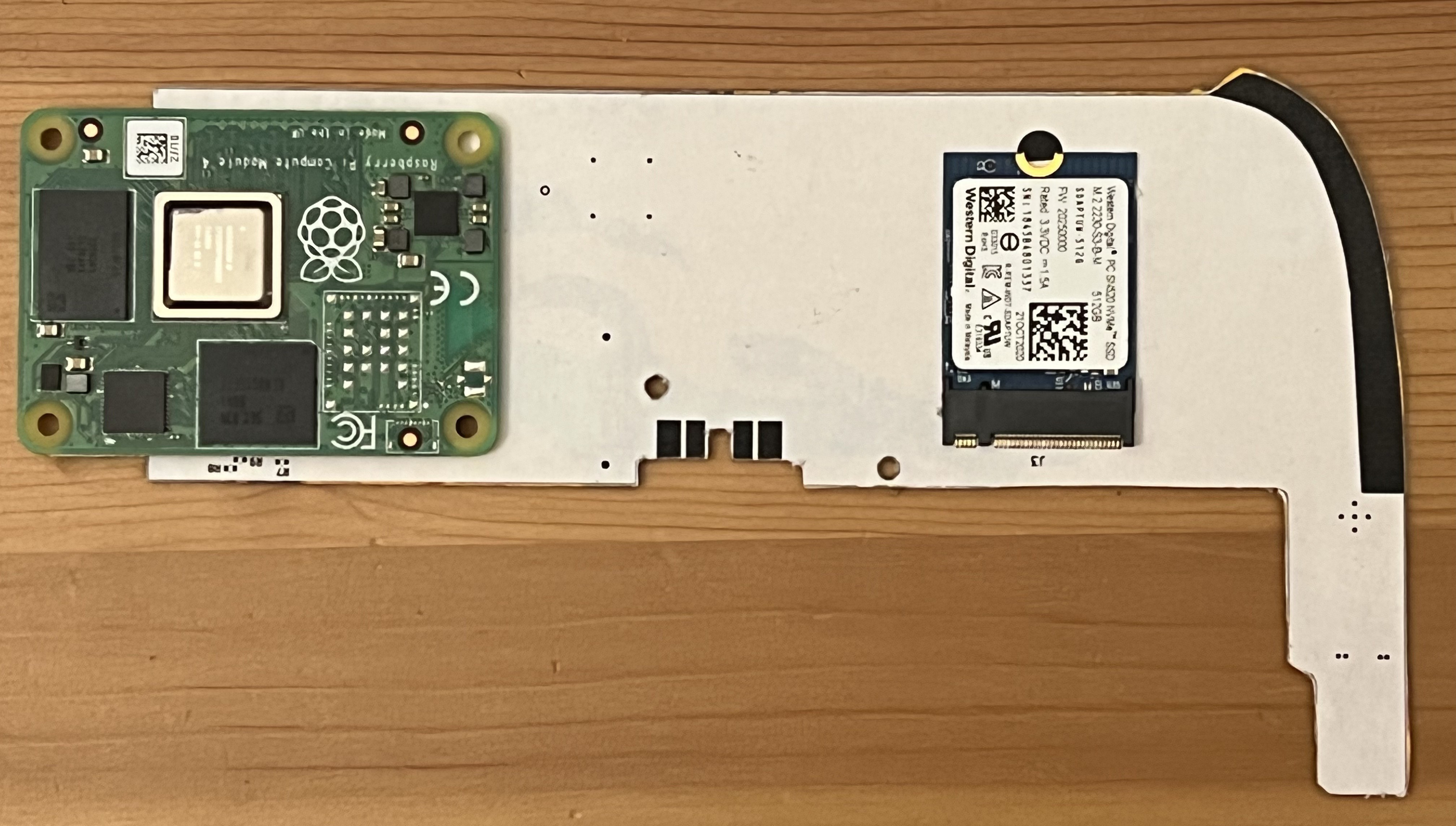
With this project, I intend to make a logic board for the original iPad based around the Raspberry Pi CM4 or another similar SoM. This will allow people to upcycle their obsolete iPads into fully-functioning tablets, which should be able to run Linux and Android.
Hopefully by giving these venerable devices a new lease on life, we can keep some of them out of landfills.
Feature status
| Feature | Progress | Notes |
|---|---|---|
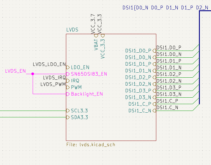
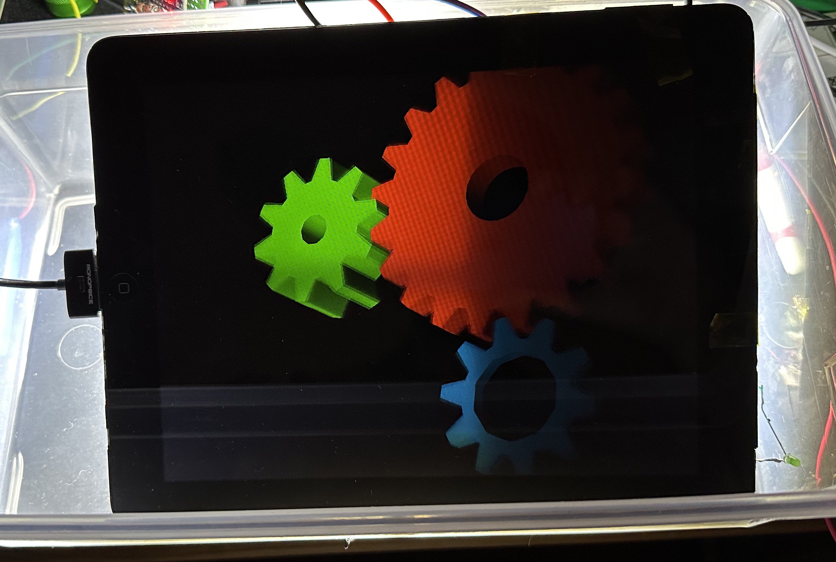
| LCD | 90% | Occasional video glitches (image ghosting, palette gets messed up), but works fine most of the time. |
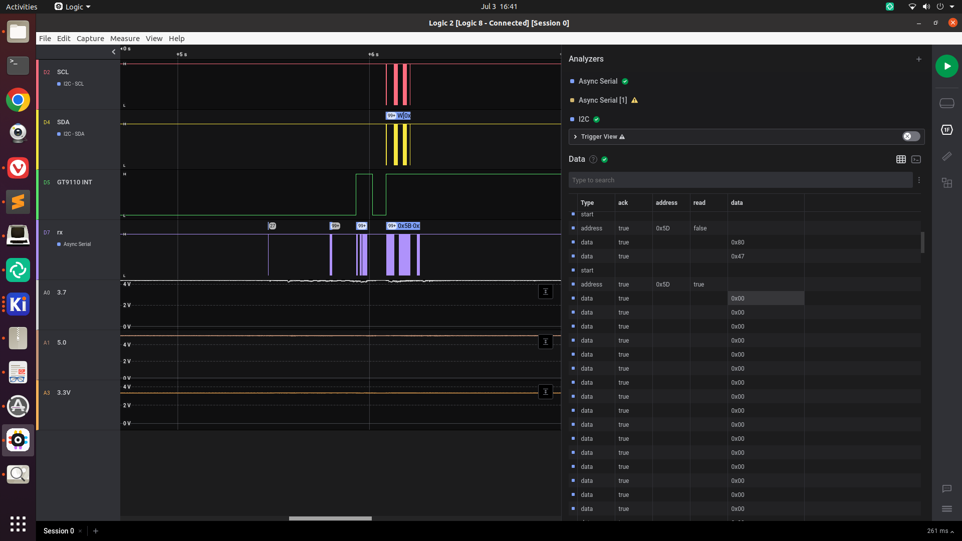
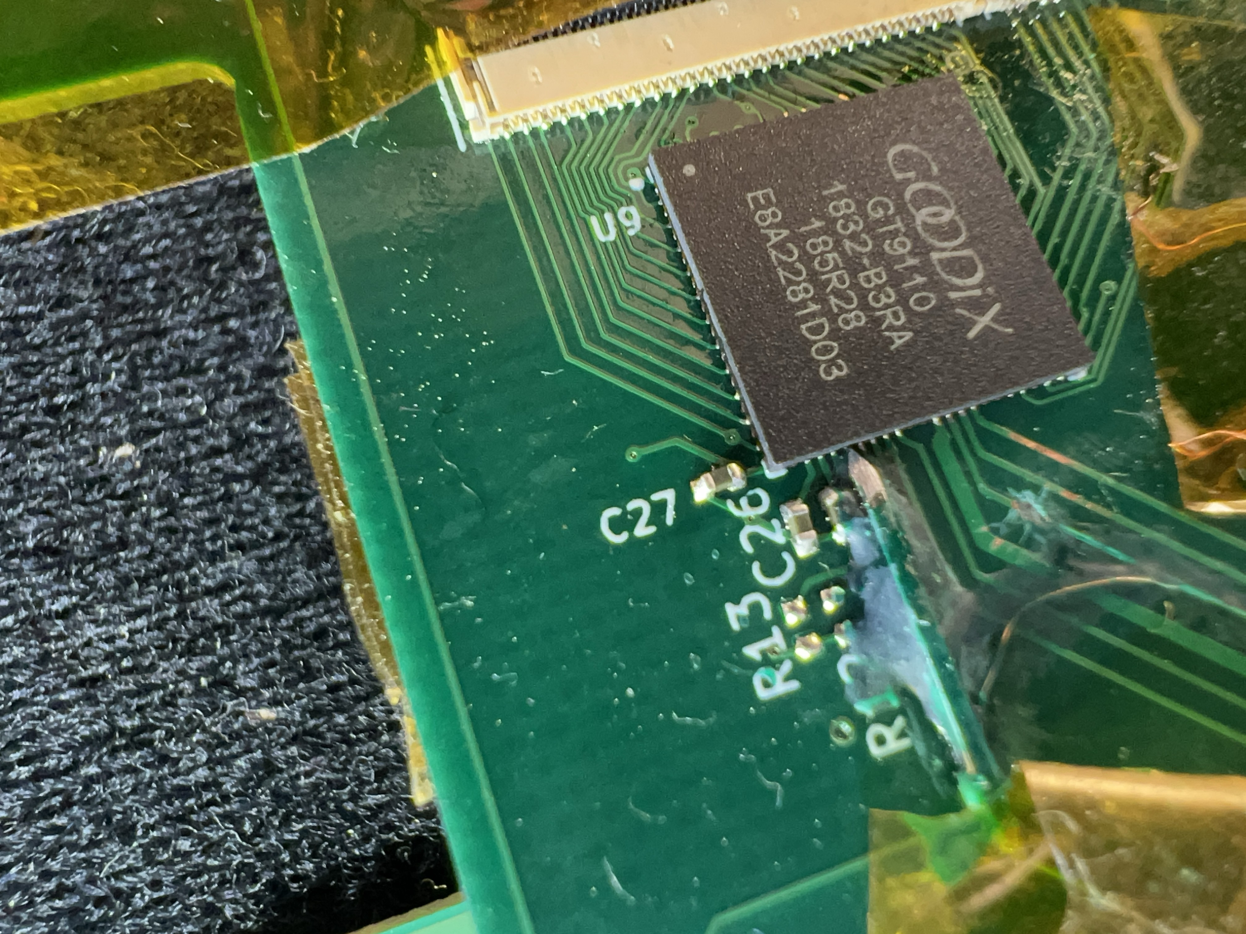
| Touch screen | 70% | Frequent phantom touches, general poor performance. |
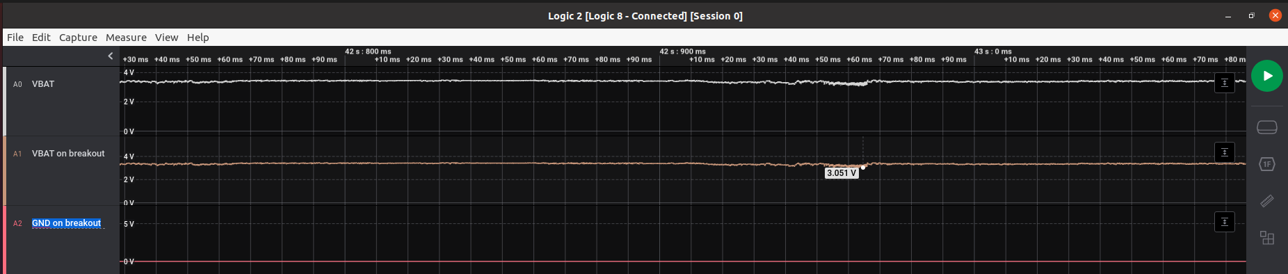
| Power management | 90% | Charging works, 5V boost works. Some circuitry changes changes needed to handle power-off correctly. At some point I'd like to get communication with the iPad battery's gas gauge. |
| Audio | 70% | Audio functions but quality is poor. Speaker amplifiers still need to be tested. |
| Wifi | 10% | Need to do one of:
With the case open, I can just use the CM4's built-in antenna or an external antenna. |
| Buttons | 70% | I need to remap one of the buttons to use nRPIBOOT instead of (or in addition to?) a GPIO pin, to support USB boot mode. |
| Nice to haves | ||
| NVMe | 50% | Circuit is designed and built on the current PCB, but needs to be tested. |
| RTC | 100% | Hardware and software side are both done, seems to work fine. |
| Ambient light sensor + Compass | 10% | Circuit is designed and wired (i2c + power) but I haven't started on the software side. |
| USB Host mode | 30% | Device mode seems to work well enough for USB booting, but I haven't done anything with USB in Linux. |
| Composite video out | 10% | Trace is wired up, but untested. |
| 30-pin accessories | ||
| Ideas for future revisions | ||
| Camera | Might require fairly little board space (just a FFC) if I can find a suitable place to mount a Raspberry Pi camera in the iPad case. | |
| DisplayPort on the 30-pin connector | This would enable the 30-pin to HDMI adapter, but would ironically require an onboard HDMI to DisplayPort converter. | |
 darkspr1te
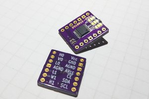
 J. Ian Lindsay
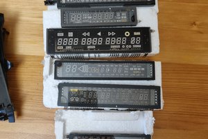
 SUF
SUF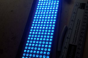
 e.potis