 Emilio P.G. Ficara
Smartphone controlled charging
I have an older smartphone that I use exclusively as a hotspot for my private wifi network. This means that I should always leave the phone connected to its charger, but I don't like that. So I decided to add a circuit that automatically connects the charger when the charge level drops below 30% and instead disconnects it when the charge exceeds 70%. Here is a photo of the device in operation:
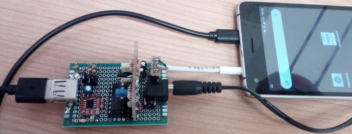
The circuit is connected, as seen in the photo, to the audio output of the phone. Why? The reason is simple. I have programmed an App for Android that runs "in the background", that is, even when it does not appear on the video. Every 3 minutes the App performs a “service” which simply consists of reading the battery charge level and the “plugged” condition ( charging ). If the level is lower than 30% and the operating status is - not charging - then it plays an audio file with the DTMF telephone tone relative to the digit “4” which starts the charge; if, on the other hand, the level is higher than 70% and the operating status is - charging - then the DTMF tone that is reproduced is that of the digit “8” which interrupts the charge in progress.
Let's see the wiring diagram, divided into sections; the first part is the circuit that interfaces with the phone's audio jack output:
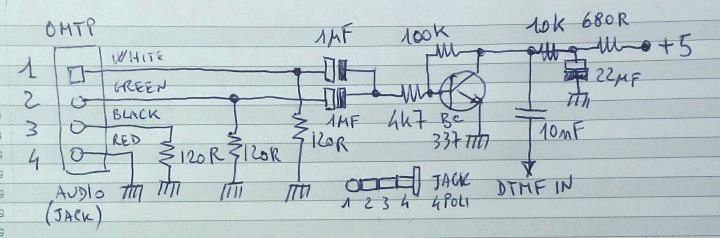
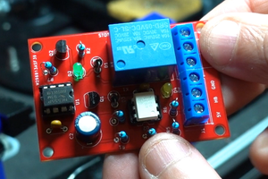
I bought a pair of 3.5mm 4-pin jacks with wired wires and USB-A output. Once disassembled, I saw that the USB plug contained a small CS with some components, so I cut the wires and connected a connector, as seen in the figure. The colors written on the diagram correspond to my jack, but they are NOT necessarily the same as those of another plug. Check the correspondence of the 4 contacts with a tester. This circuit mixes the two left-right channels and amplifies the signal. The 120 Ohm resistors at the input are used to charge the smartphone output. Without them, the phone does not notice that it has a connected circuit. To tell the truth, in an A5000 smartphone (year 2011) any jack is inserted activated the audio output. Well, you see the circuit output connects, via a capacitor, to the next DTMF tone decoding module. Here it is below:
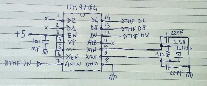
The UM9204 chip is very common (and very old) and I got it from a circuit presented on an old page of mine . The operation is simple: the audio signal present on pin 7 (dtmf in) is analyzed and if it corresponds to one of the DTMF tones used in telephony (mix of precise frequency pairs) the DV line (data valid) is brought to a high level and on the lines D1..D8 the combination in binary relative to the digit appears. Note: the "0" comes out as ten (binary 1010). Now, we will use the DV, D8 and D4 lines for our purpose. Obviously, the D8 line will not be high only when the tone relating to the digit "8" is present, but also for the "9" and "0", as well as the D4 line will be high with the digits "4", "5”, “6” and “7”, but for this application there is no problem.
The DTMF tone emitted by the phone lasts about 200mS (the .ogg files I generated with Audacity , an excellent open-source software for processing audio files) and therefore the DV, D8 and D4 signals are temporary, while we need a stable command signal, both for the on and off conditions. So, we need a flip-flop and we make it with the most classic of logic gates: NAND. Here is the circuit:
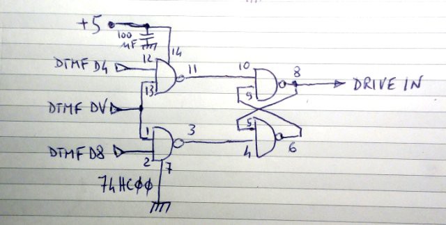
A classic Flip-Flop set / reset. The section on the right is the actual flip-flop, the one on the left we need because the set-reset needs a low level to activate and instead D8 and D4 go to a high level, as well as DV. So, the section on the left behaves like this: on pin 11 and on pin 3 in idle conditions we have a high level and the output - drive in- is in a stable state (it can be high or low, it depends on the previous condition). When the dtmf decoder receives a tone “4”, the DV and D4 lines become high and remain there for...
Read more »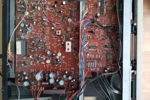
 Entunassa
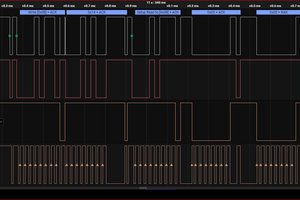
 Sergio Ghirardelli
 Electroniclovers123