Nelson Phillips
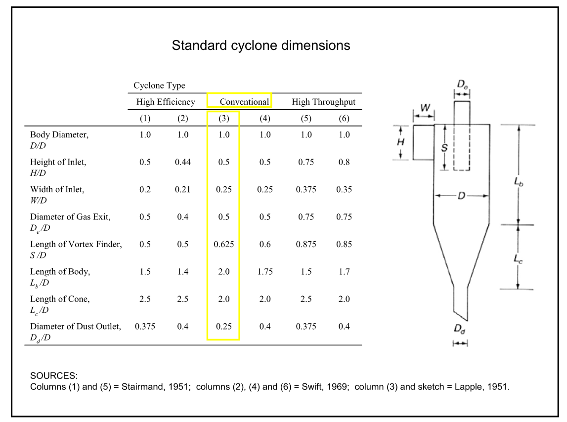
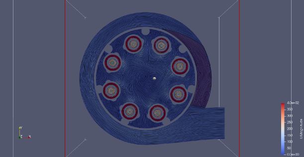
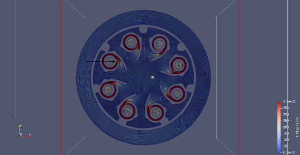
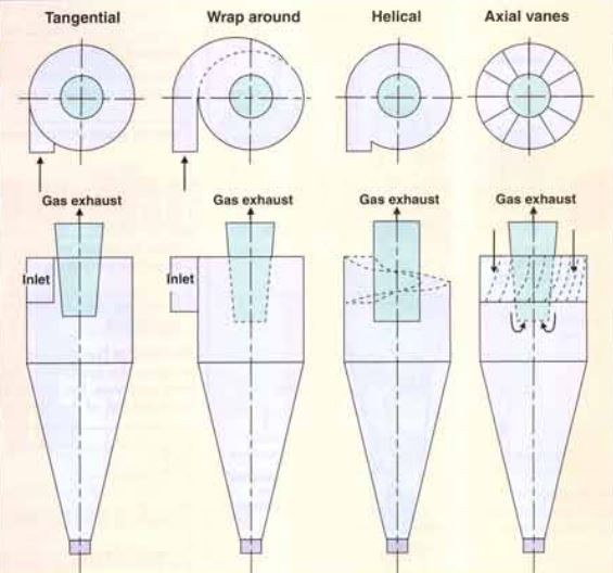
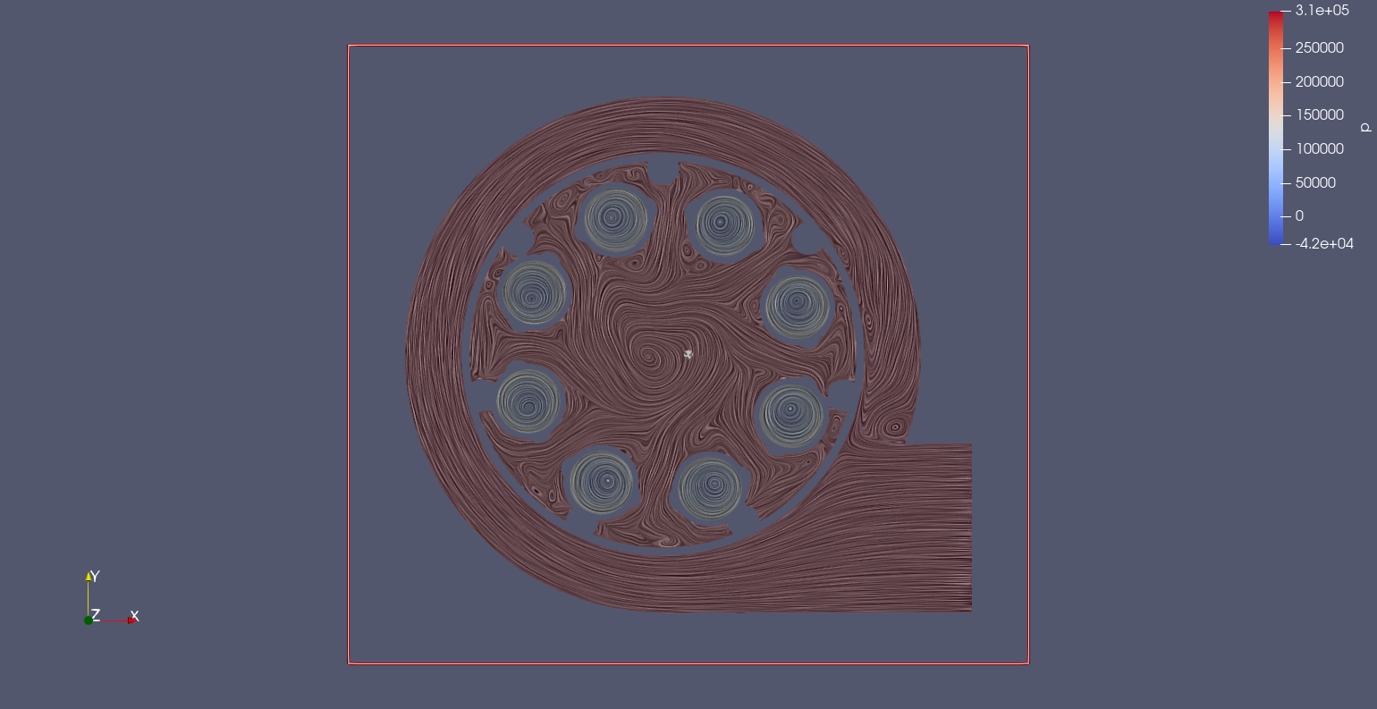
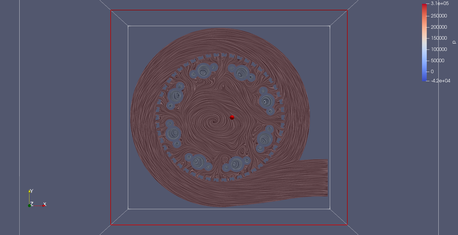
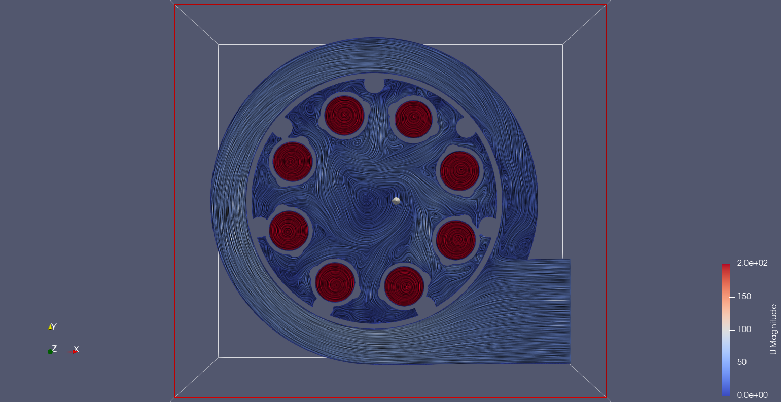
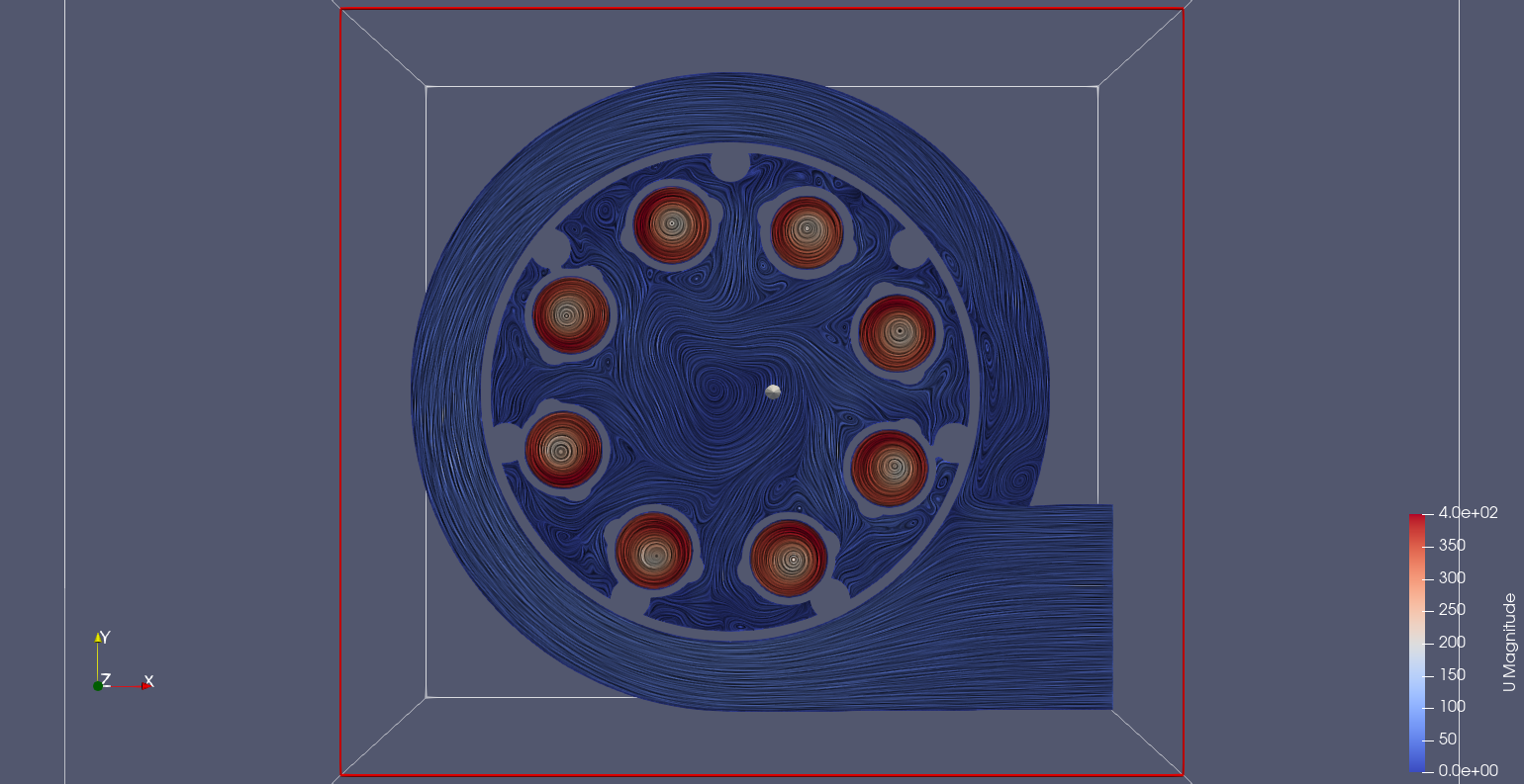
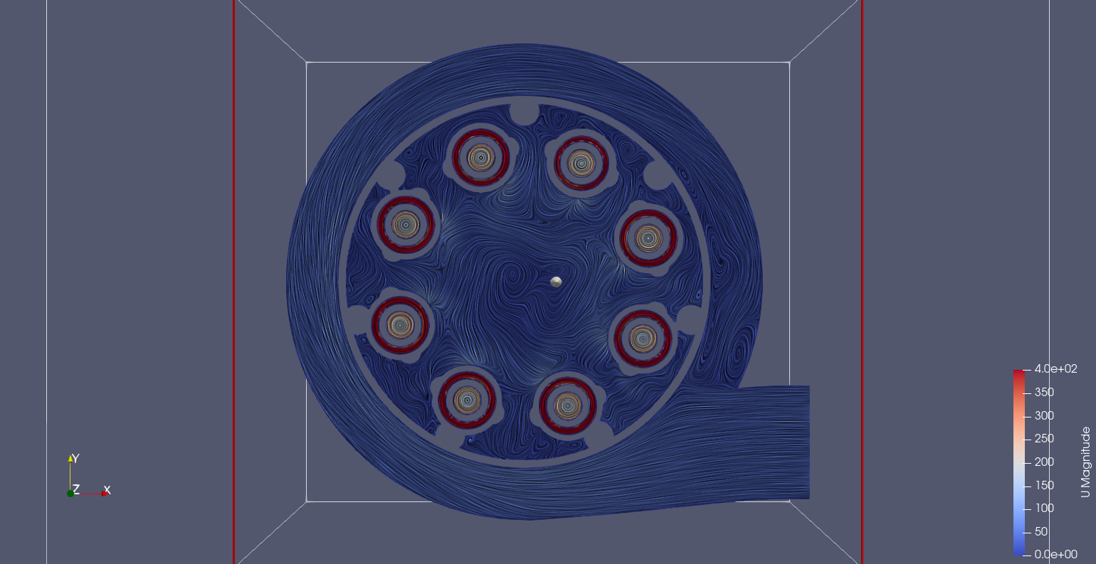
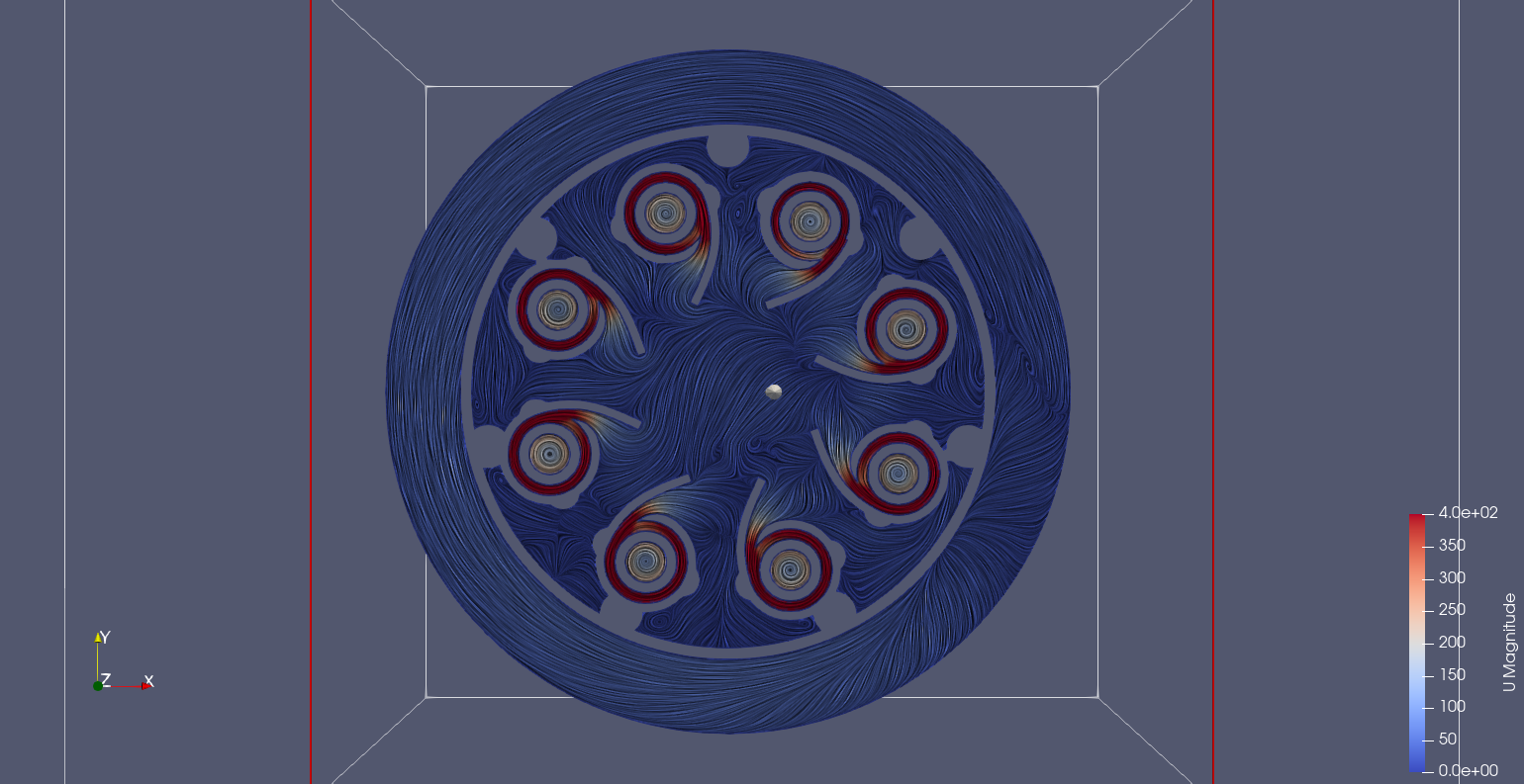
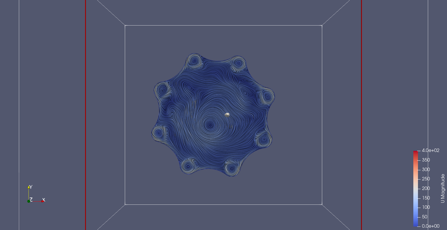
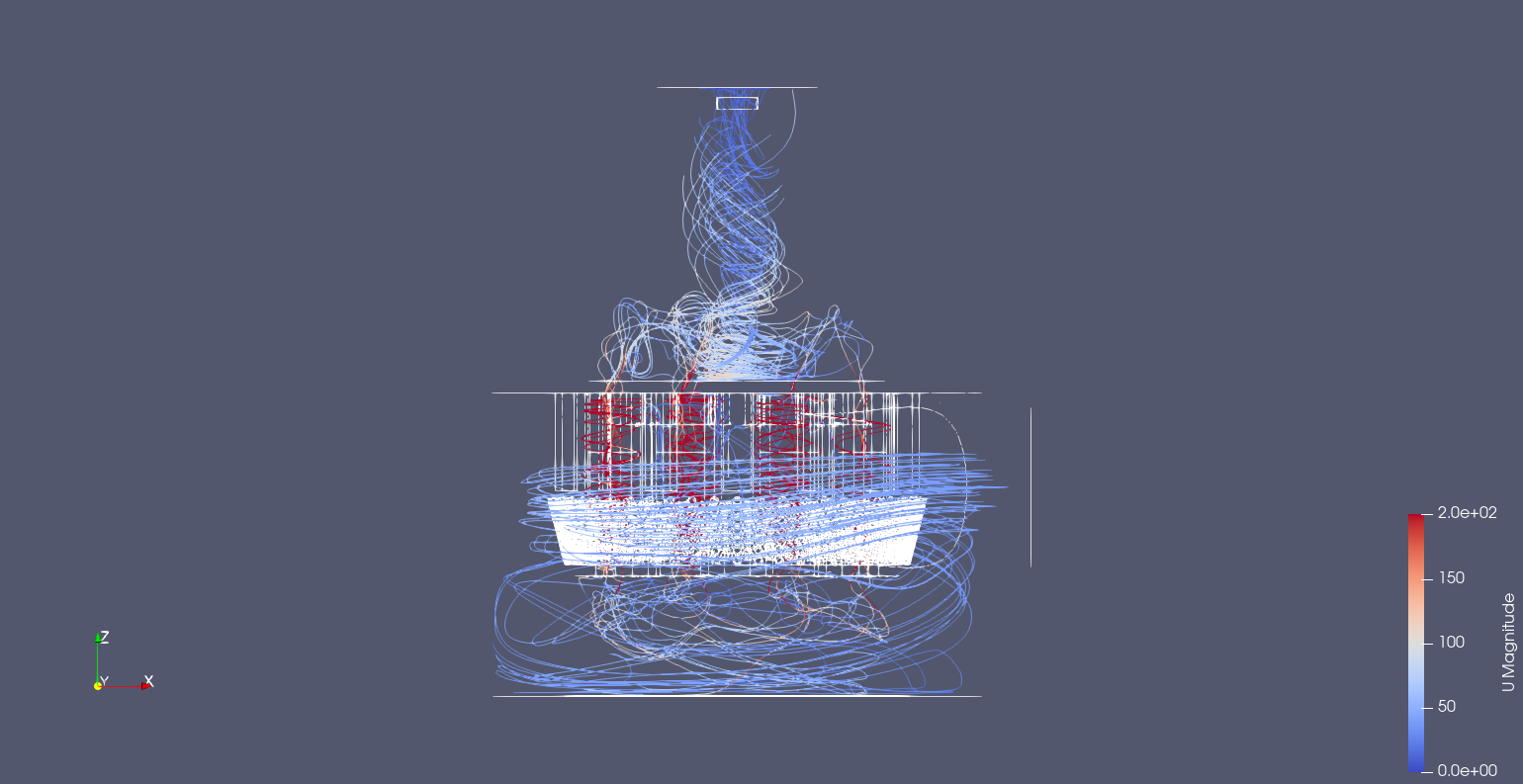
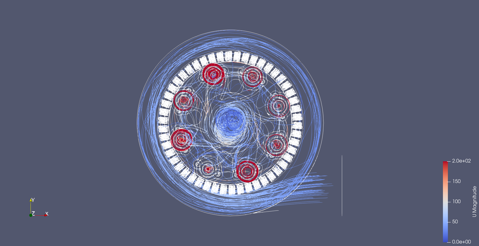
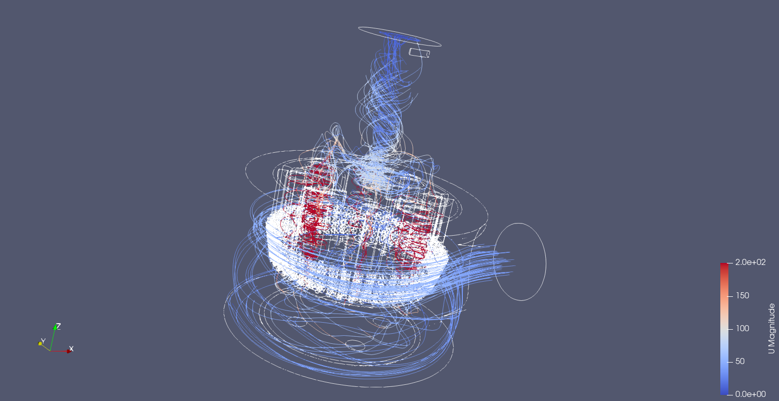
There are a number of parameters that I am working with for the design of the cyclone module. If you use the available literature that is easily find they are work from a geometric perspective where there is suggested dimensions of the features according to expected performance. This seems to be based on experimental data or at least someones experience, which is good, but I have access to CFD (computational fluid dynamics) that will help me understand the internal flow. It also means that performance characteristics of the air the vacuum pulls is now require and will determine the justification of the designs.
One of the key design parameters is the Air Watts.
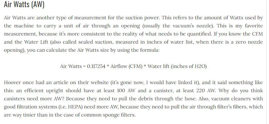
Using 200AW this equates to a CFM of
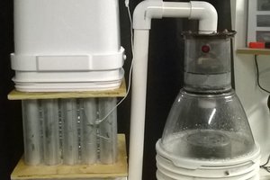
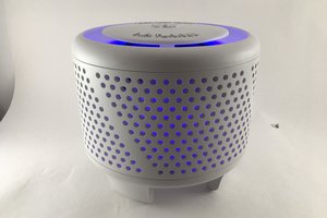
Early iterations of the dust extractor was based on the geometrical guides
 From the initial three version created the conclusion is that filtering large materials is not difficult and can be done in a crude way. Such a cavalier attitude is not possible from small particles. Then the smallest particles really need a comercial solution like a HEPA filter.
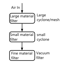
This therefore is the reason for the focus on the small sized extractors.


 Josh Starnes
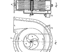

 Anteneh Gashaw