 John Anderson
This project explores a simple concept and takes it in many different directions. It combines art and engineering with nostalgia. It even took a turn I had never anticipated when fans of my pieces asked if they were available for their vision impaired significant others that play table top roll play games. Thus several display-less pieces were built and given away.
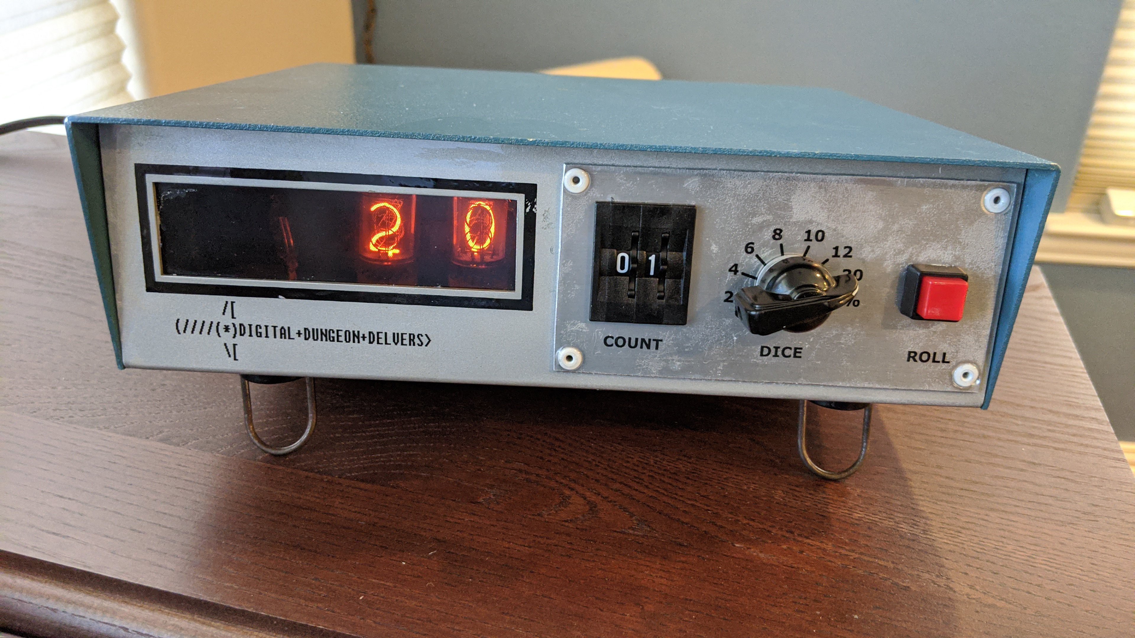
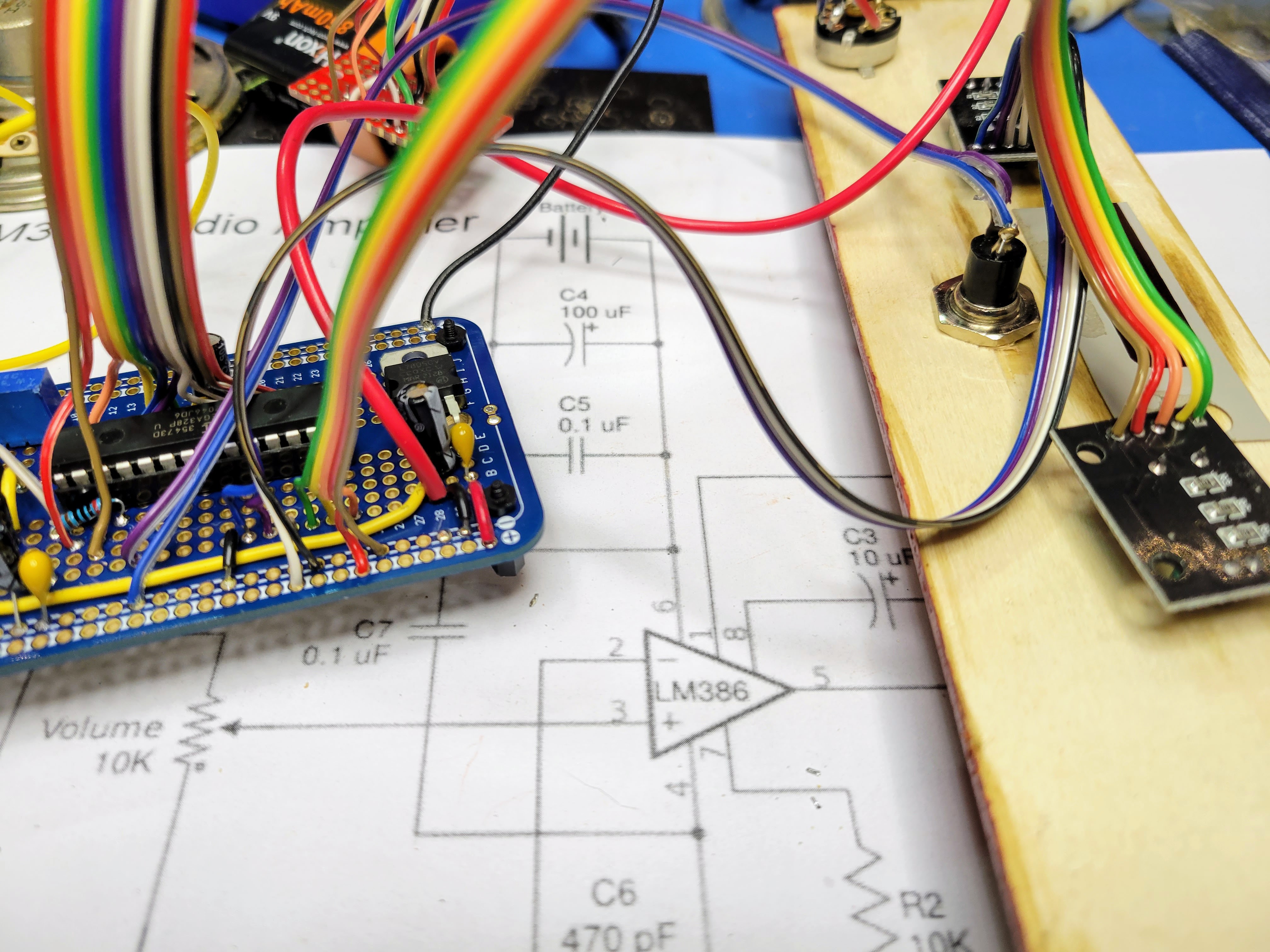
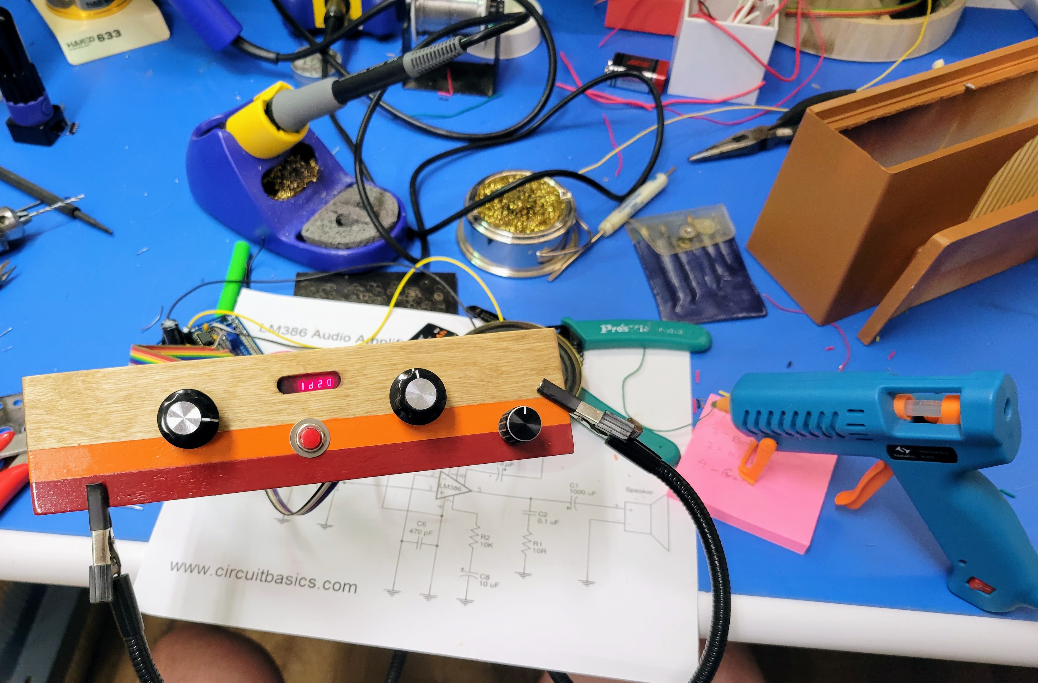
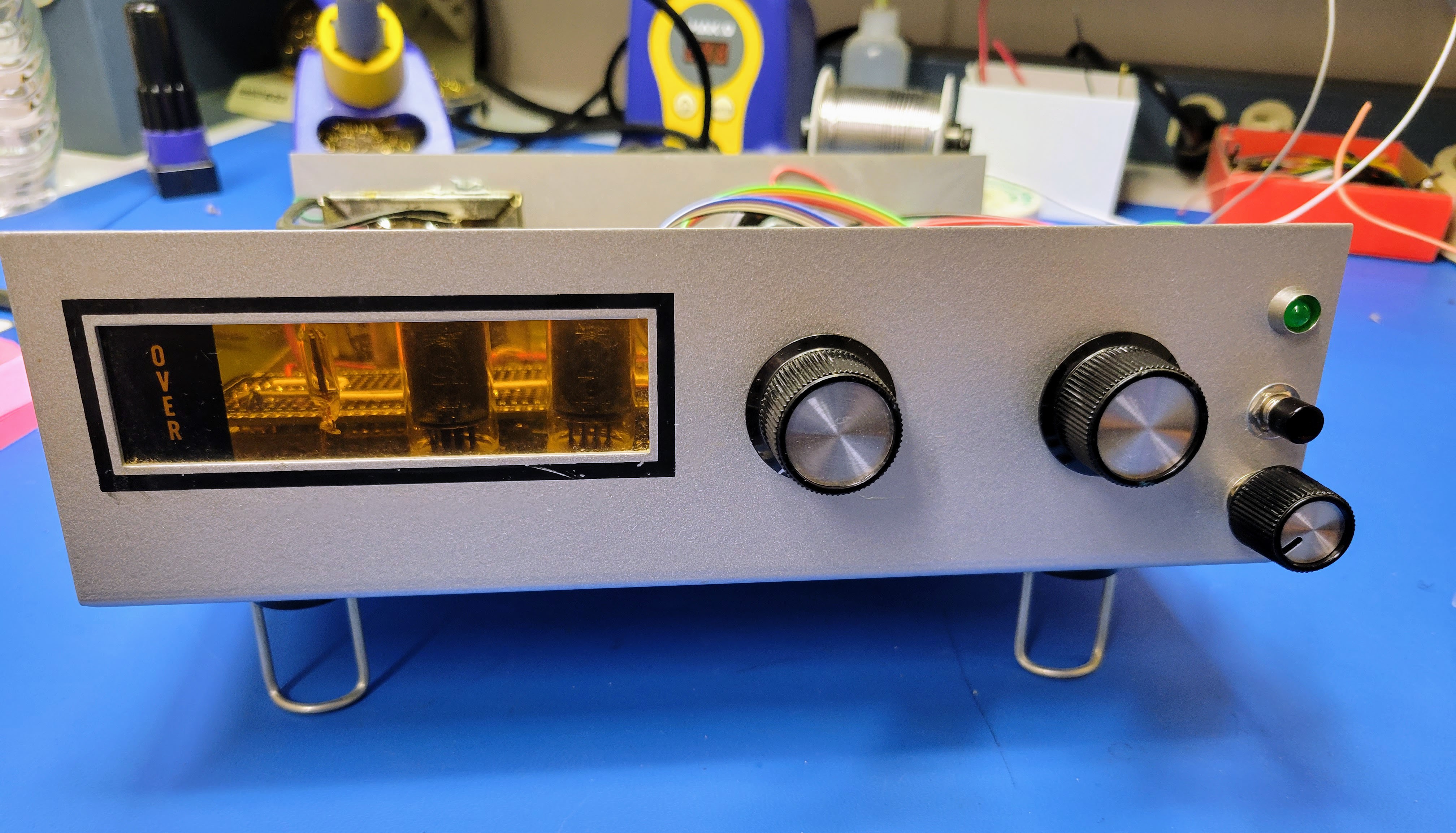
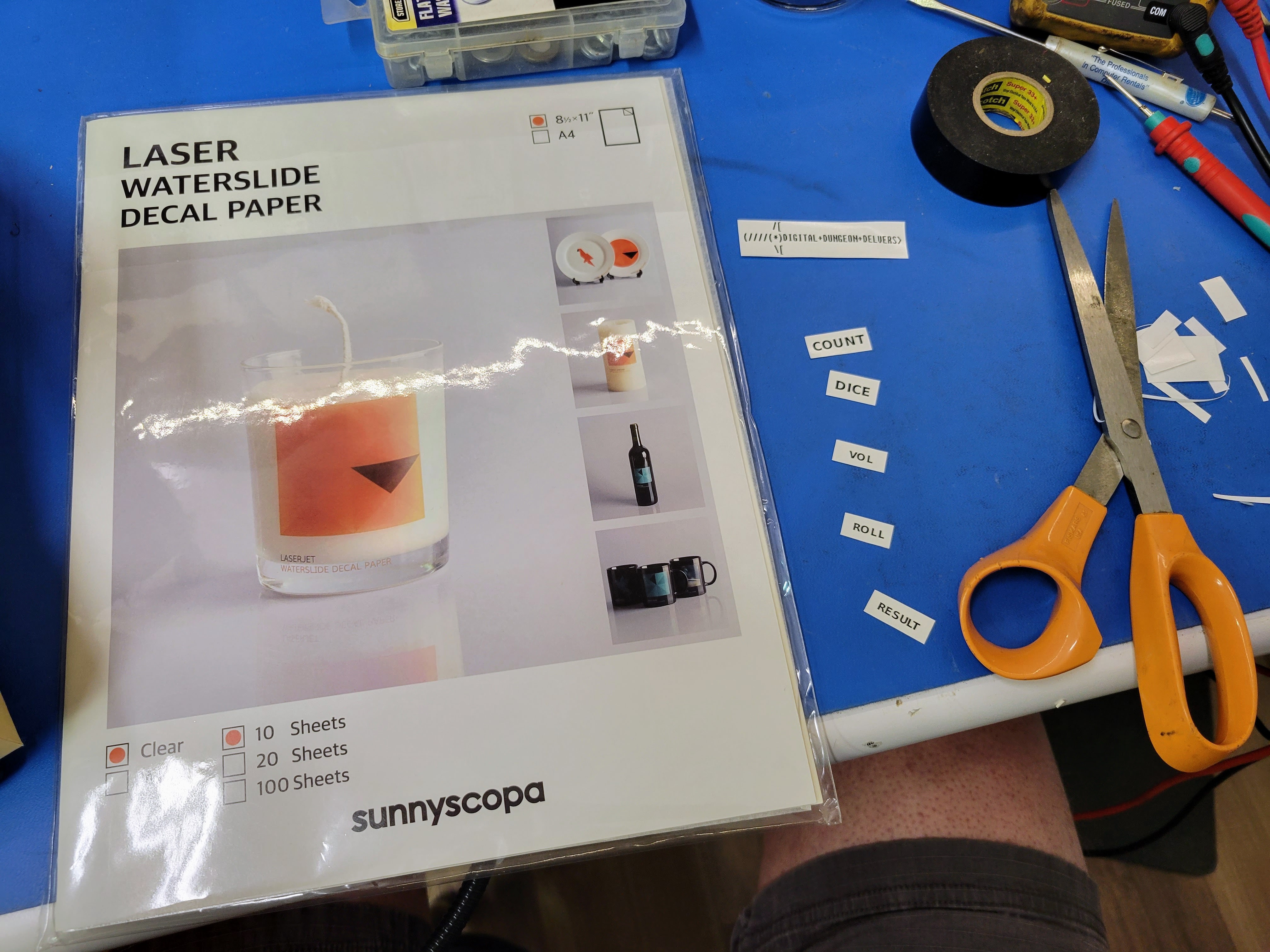
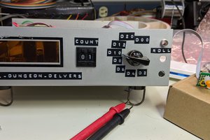
Each piece implements the function of a Dungeons and Dragons dice tower and dice using retro cases, input switches, and displays. The user selects a number of dice, then selects the dice type (2 sided, 4 sided, 6 sided, 8 sided, 10 sided, 12 sided, 20 sided, or 100 sided), and finally presses the roll button to get a die roll result. The device calculates the result then displays it and/or speaks it. The user can then re-roll by pressing the roll button again, or change the count and/or dice and roll a different set of die.
This project represents several things l love.
- It's Dungeon & Dragons: I've been playing D&D since 1978. Thus, it's a resto-mod build based on user interface technology from that same time frame
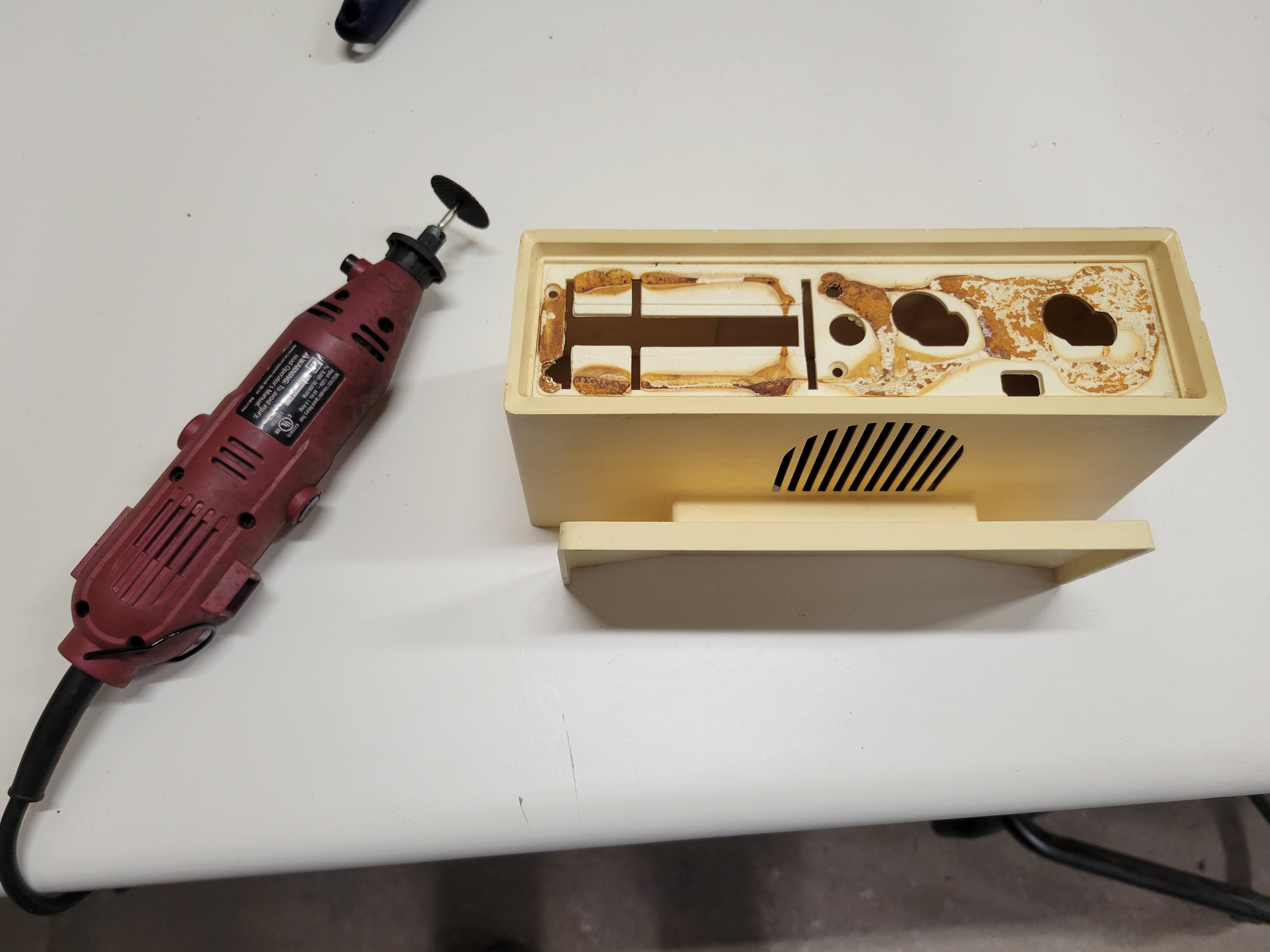
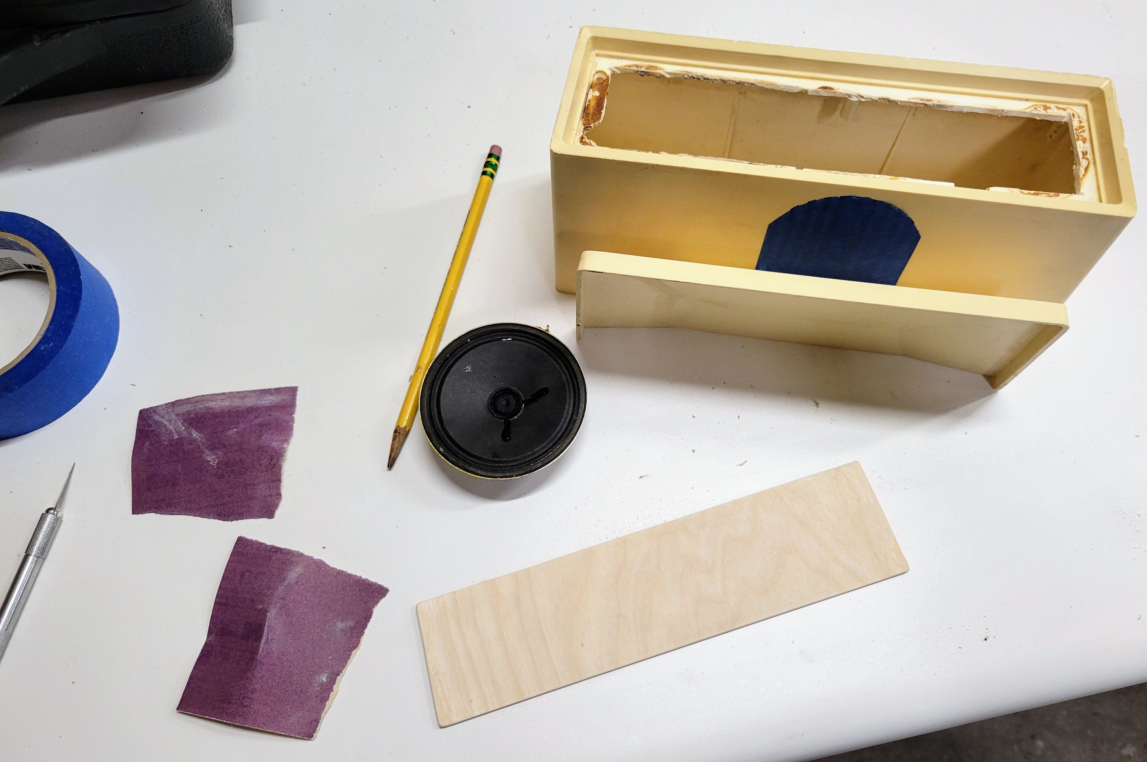
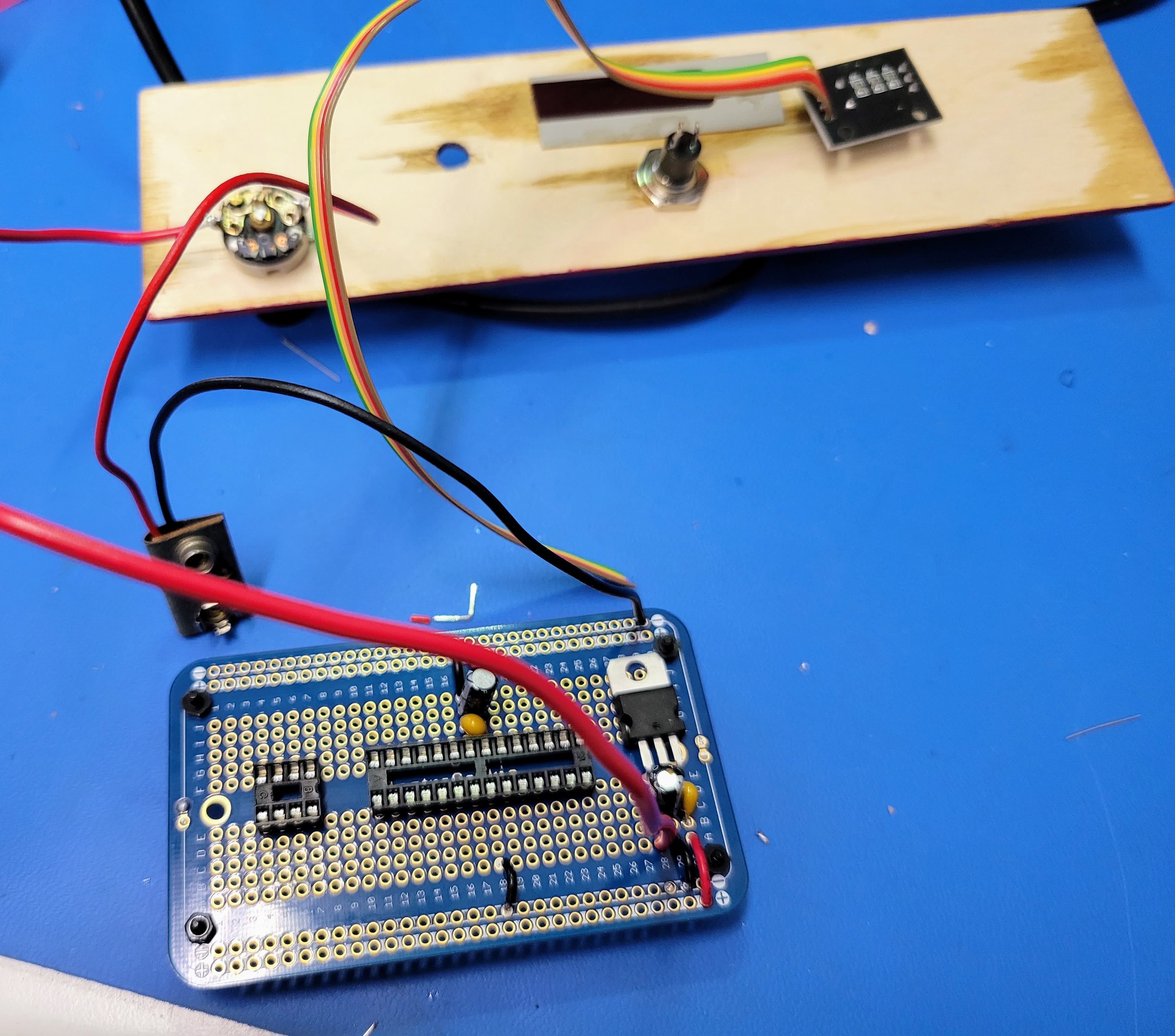
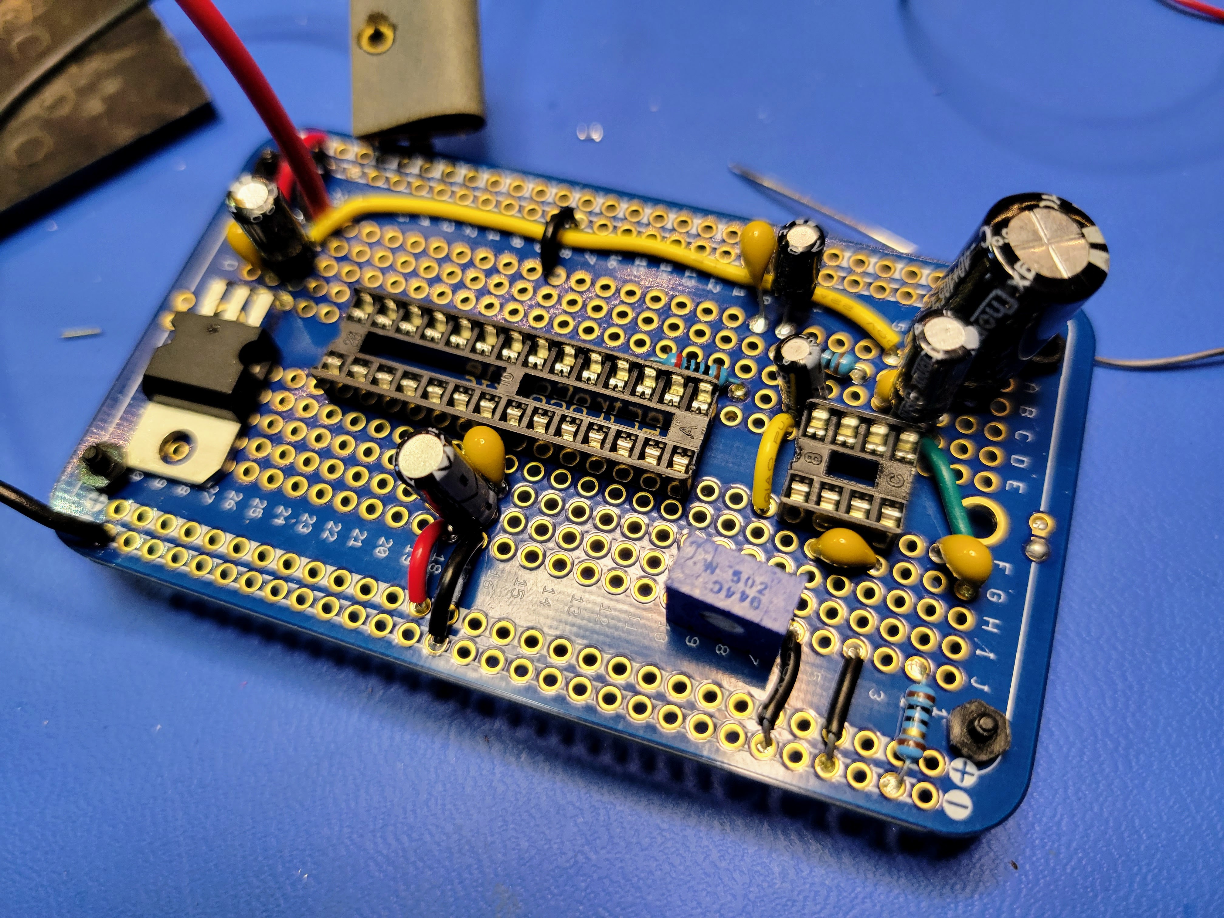
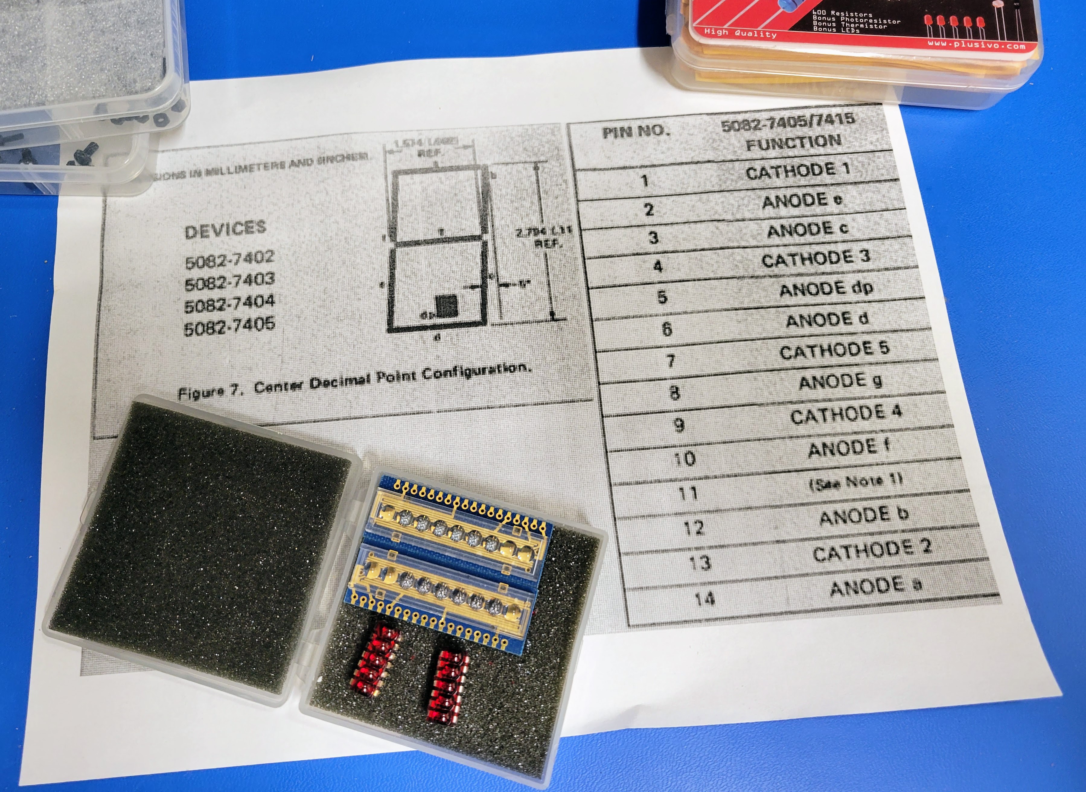
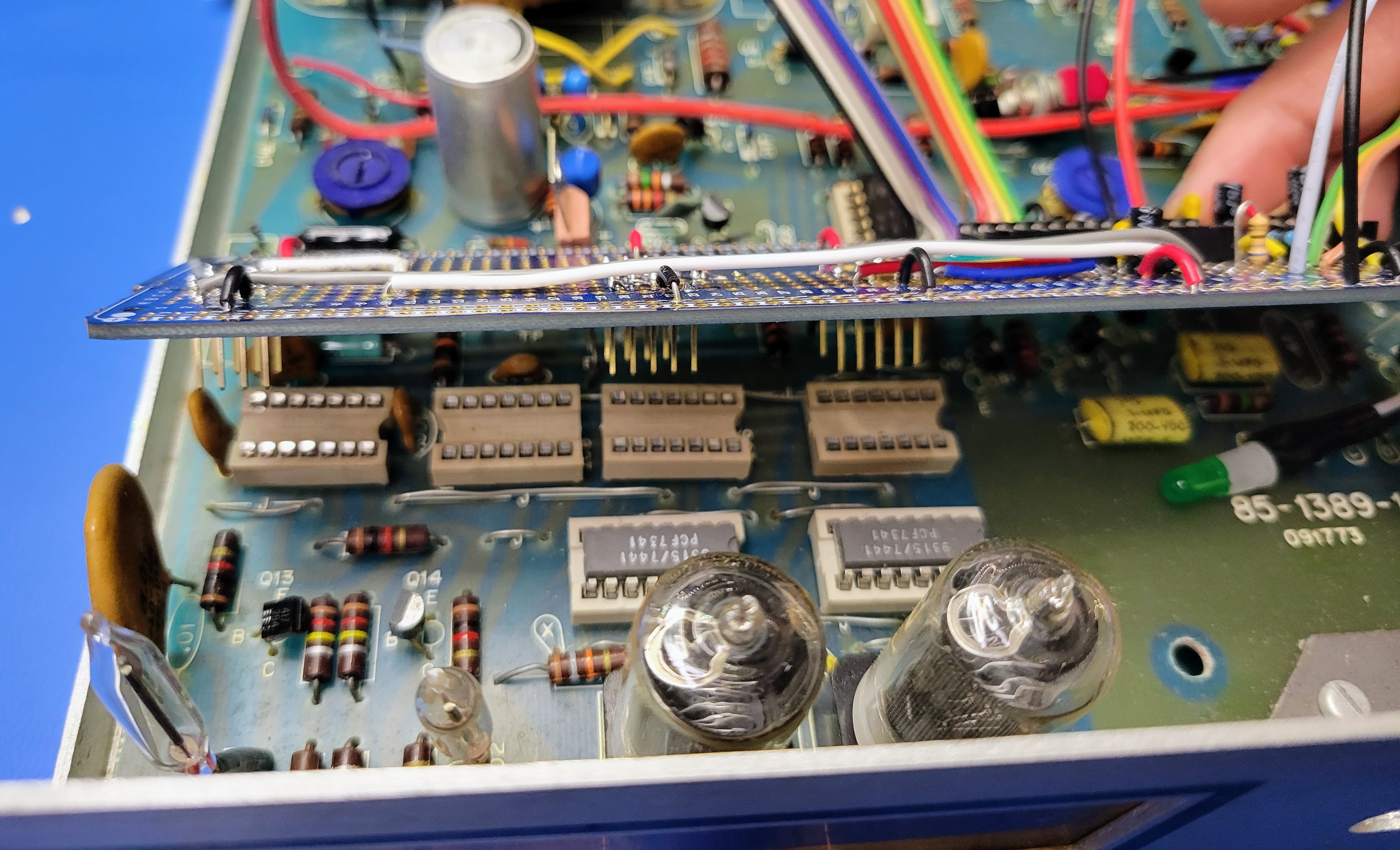
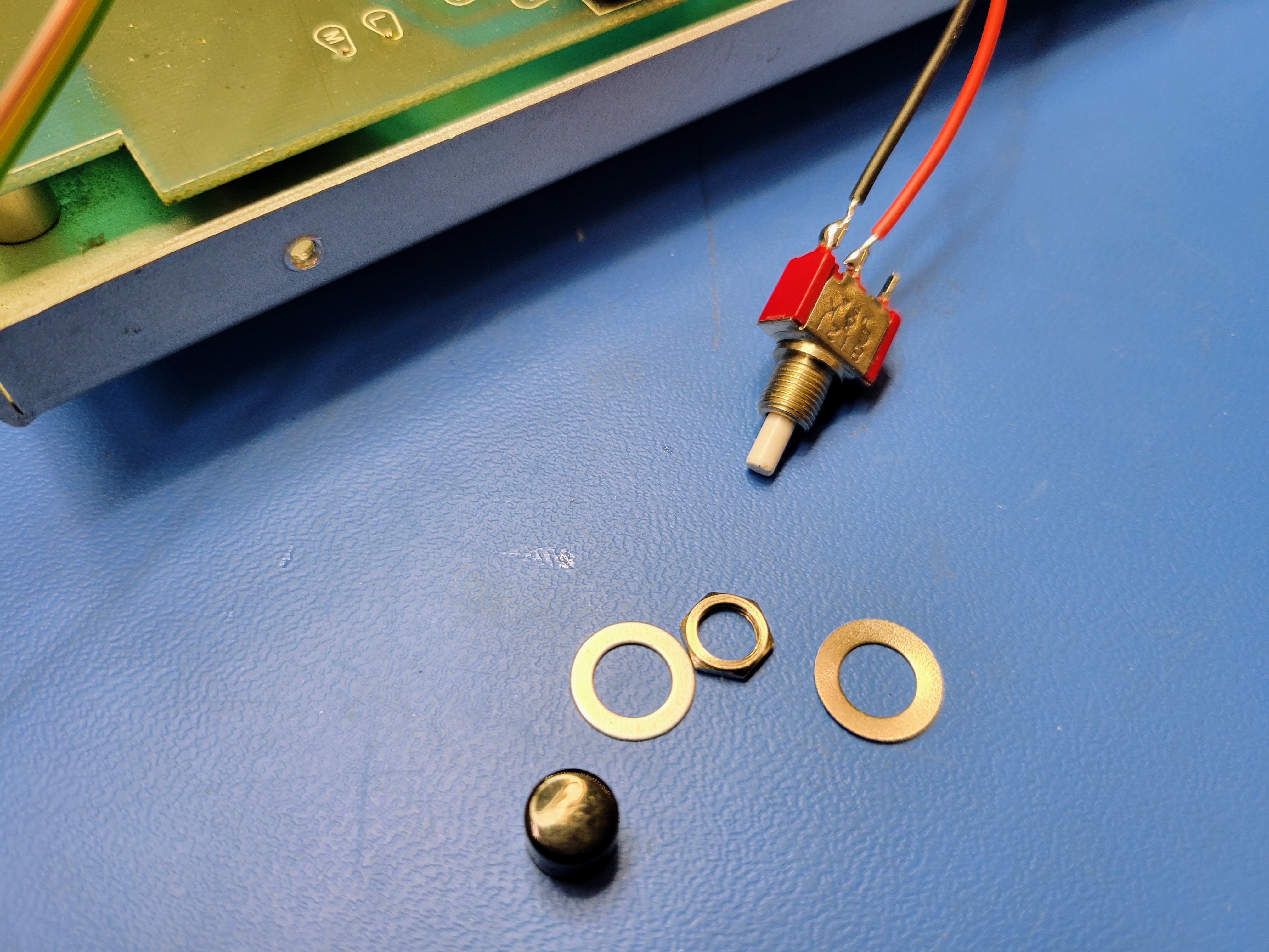
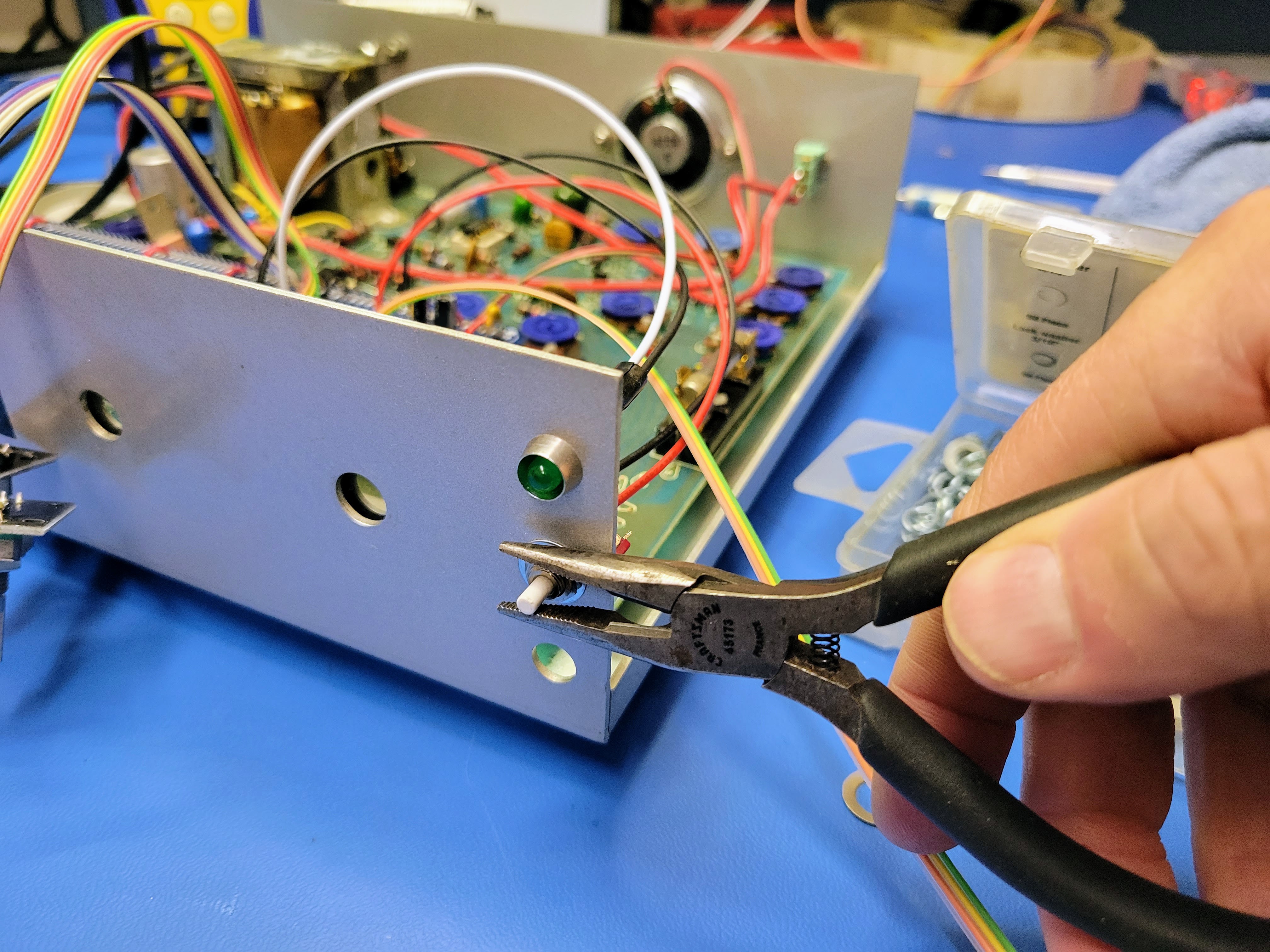
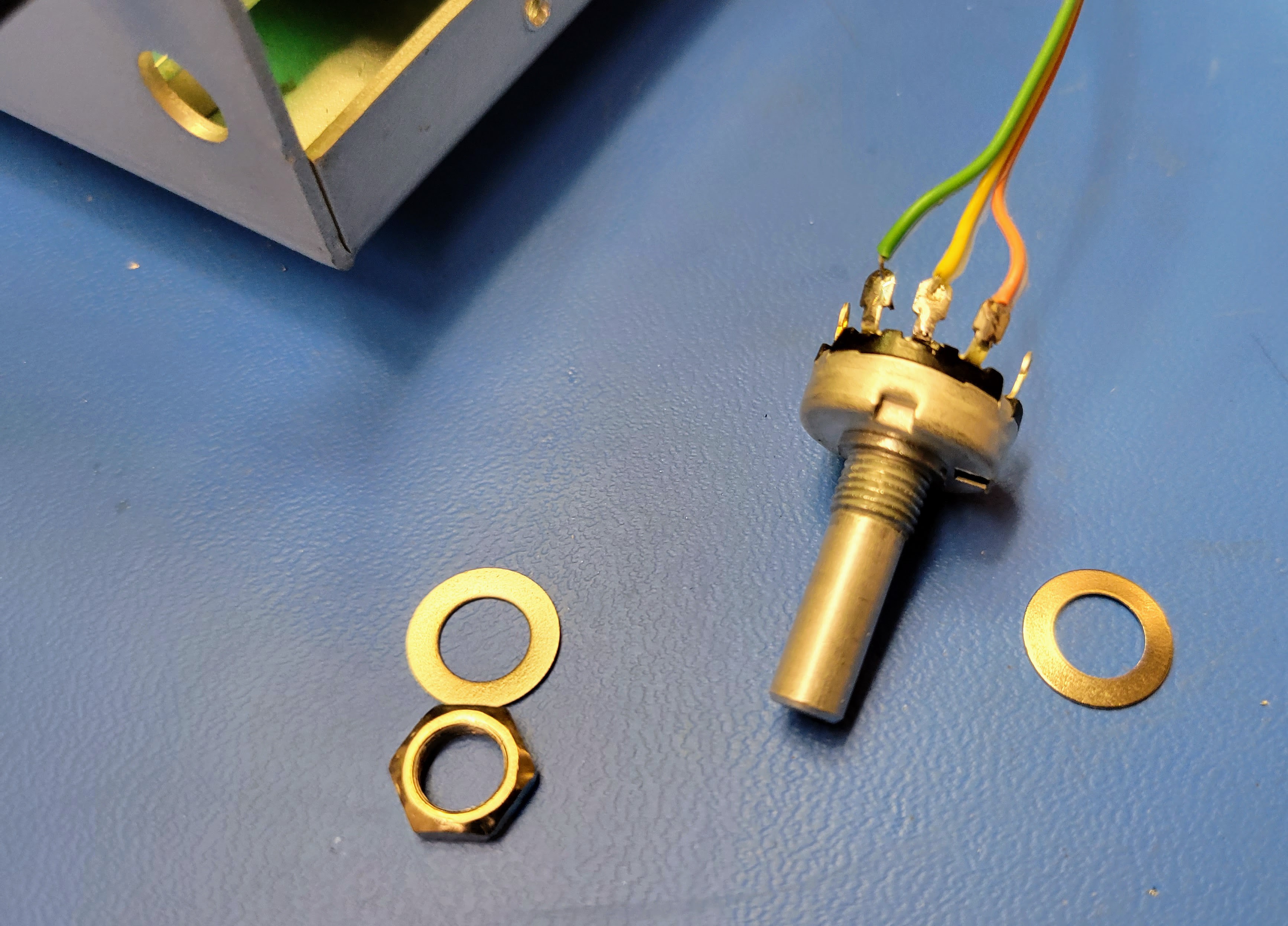
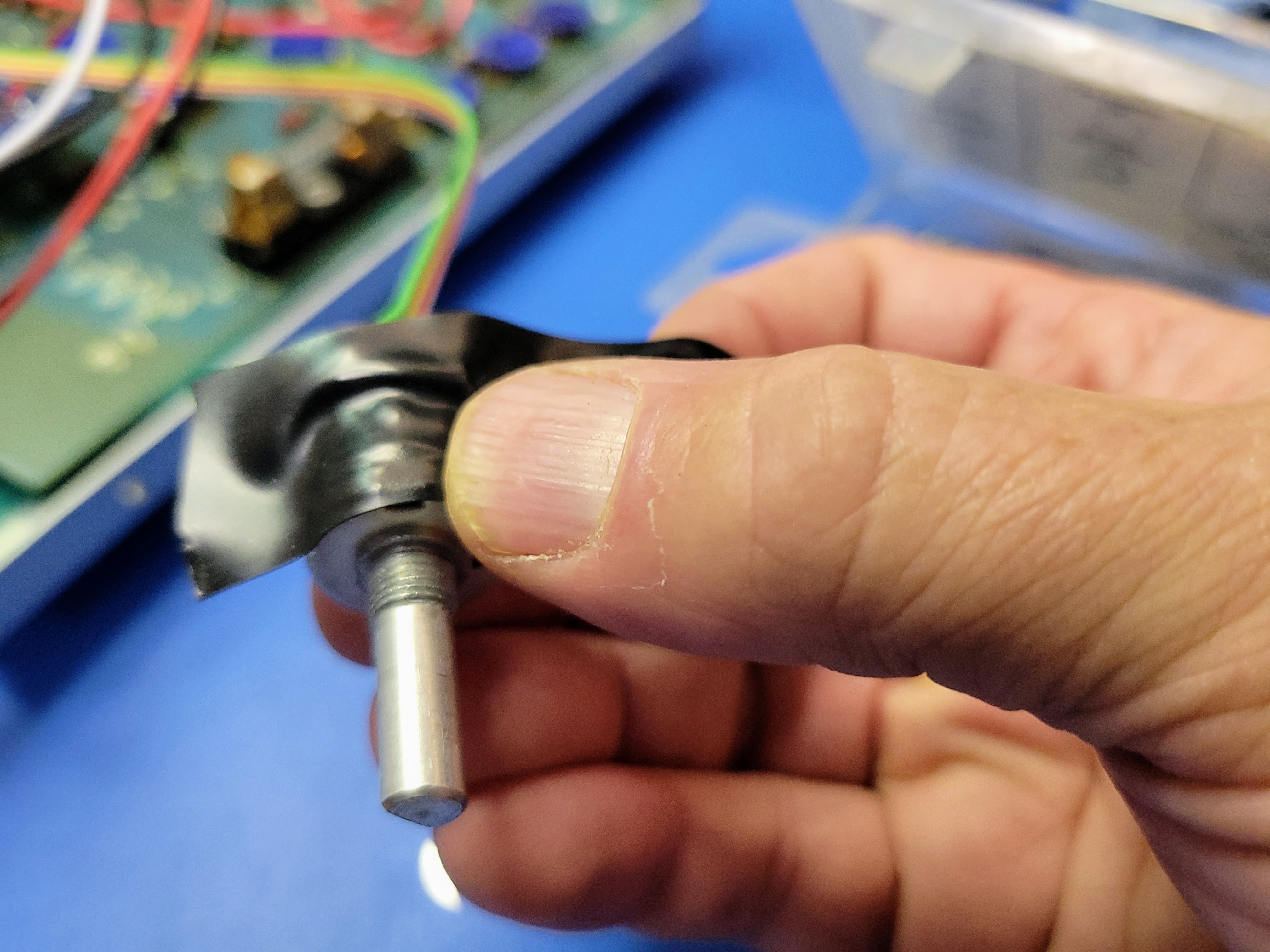
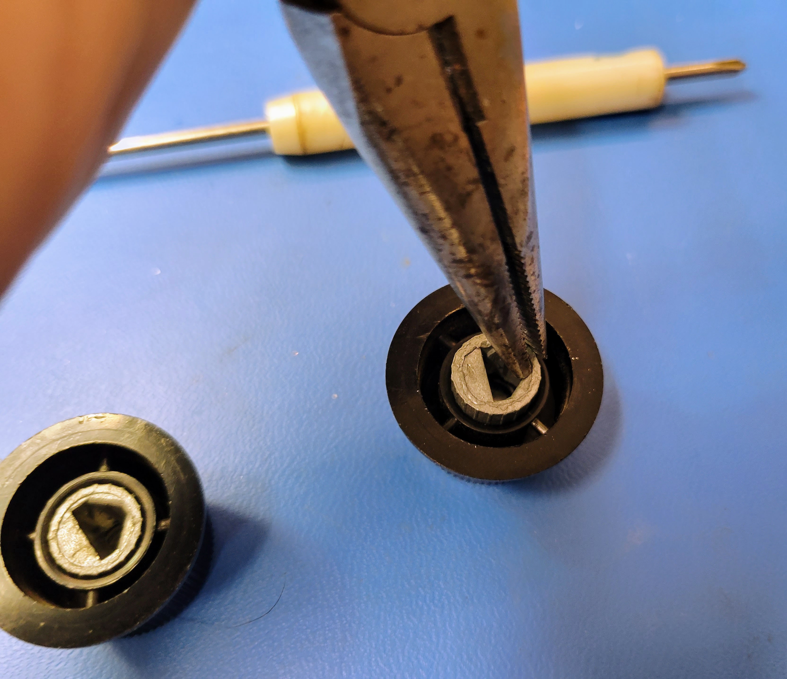
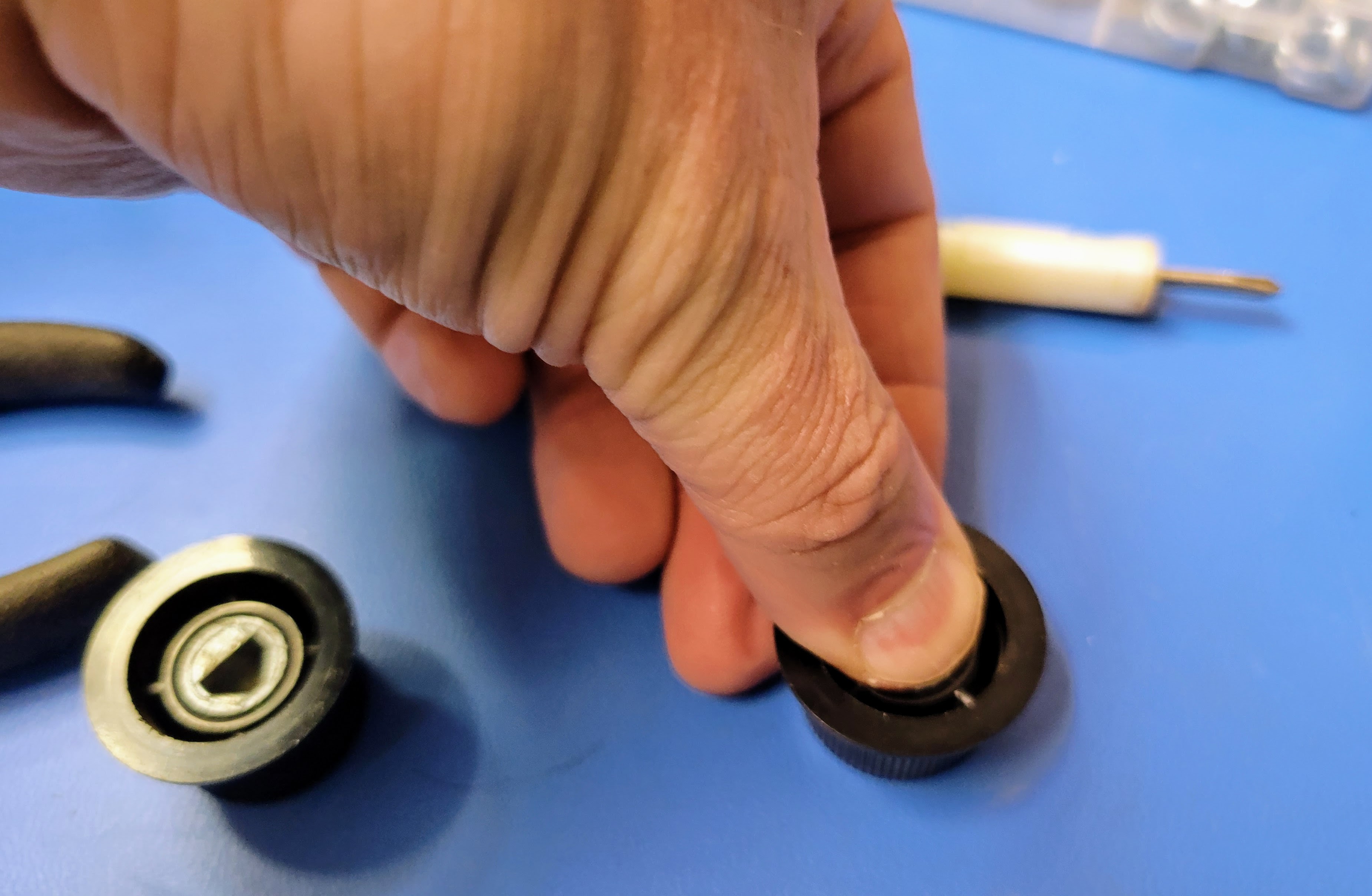
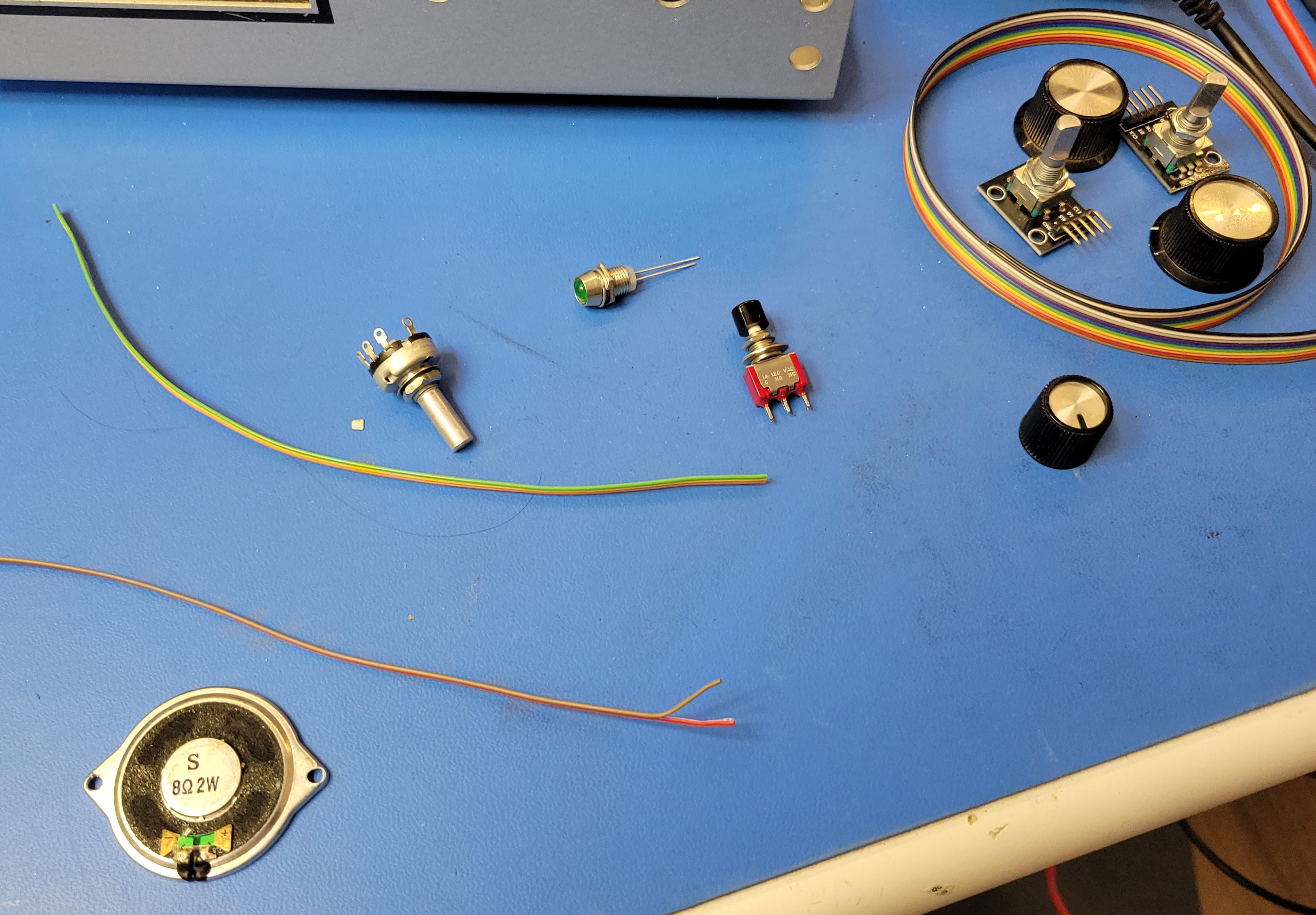
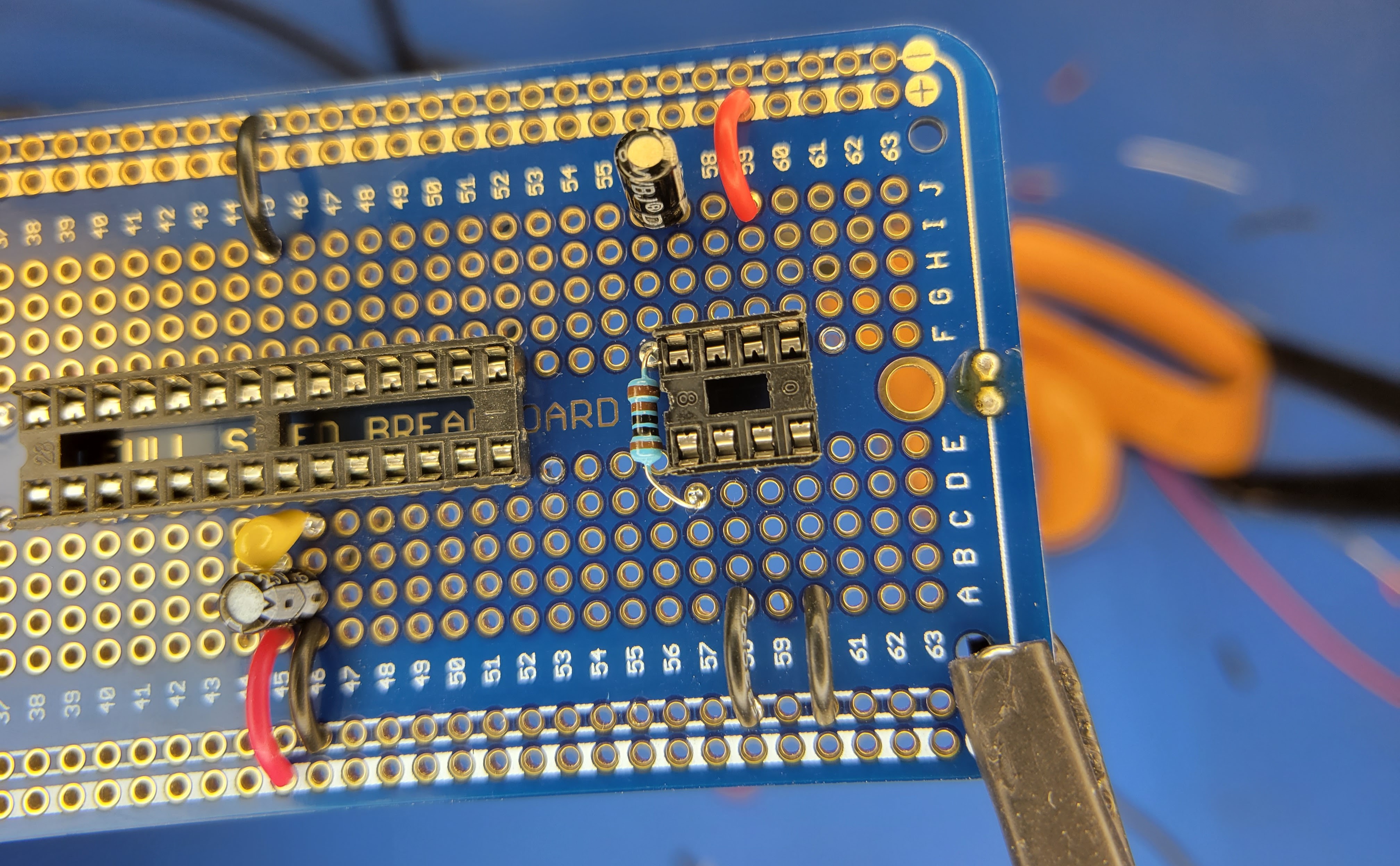
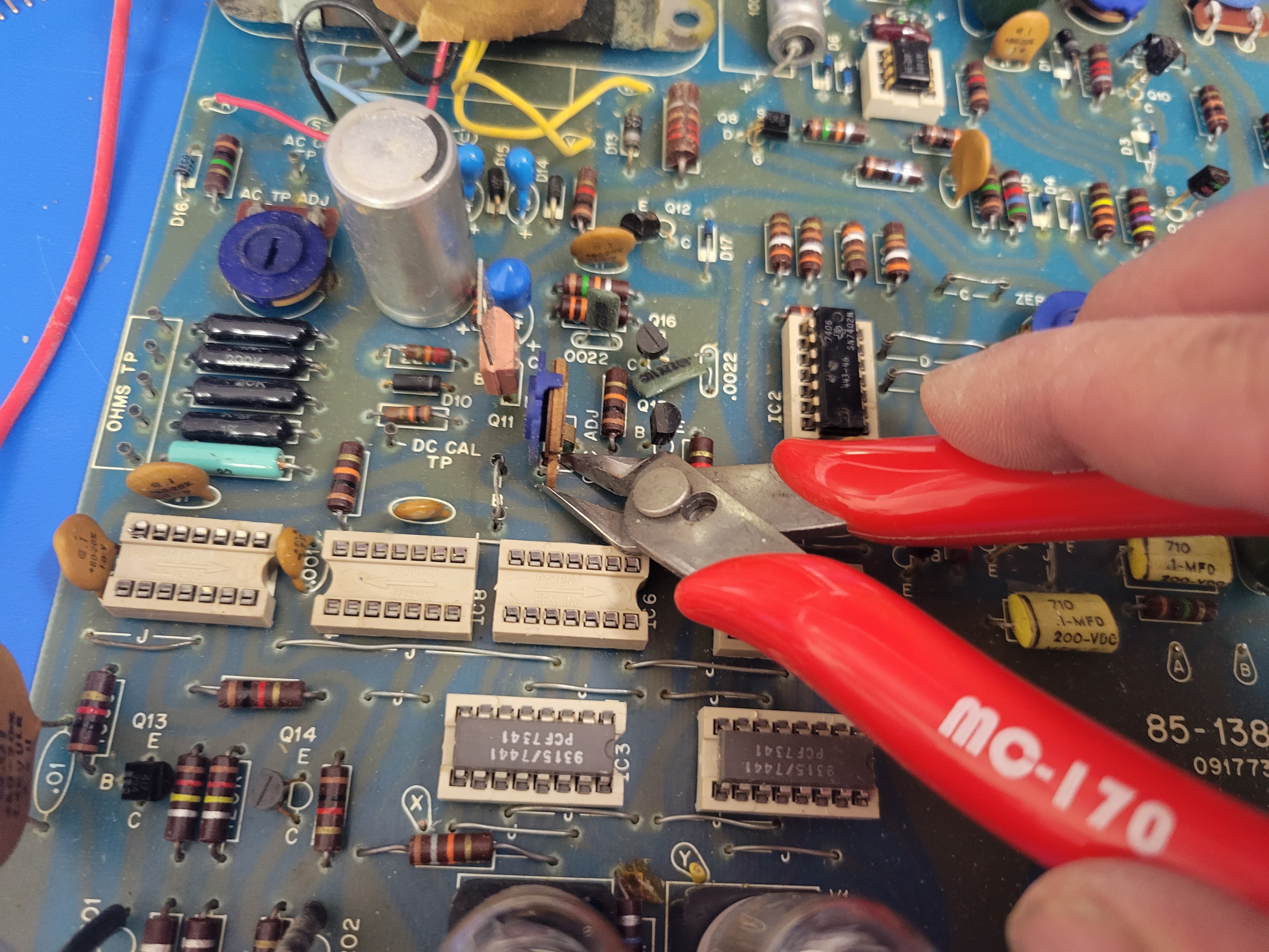
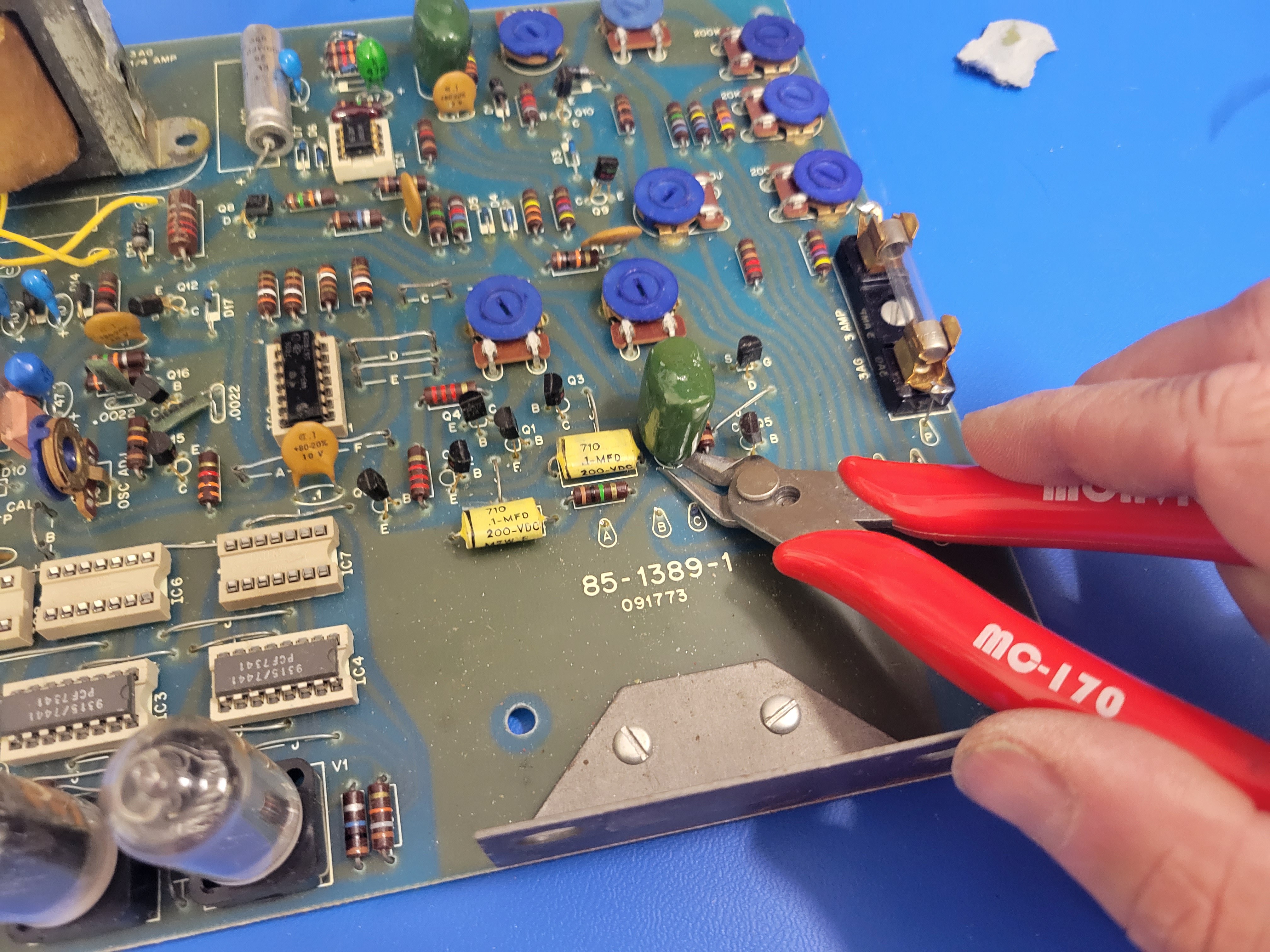
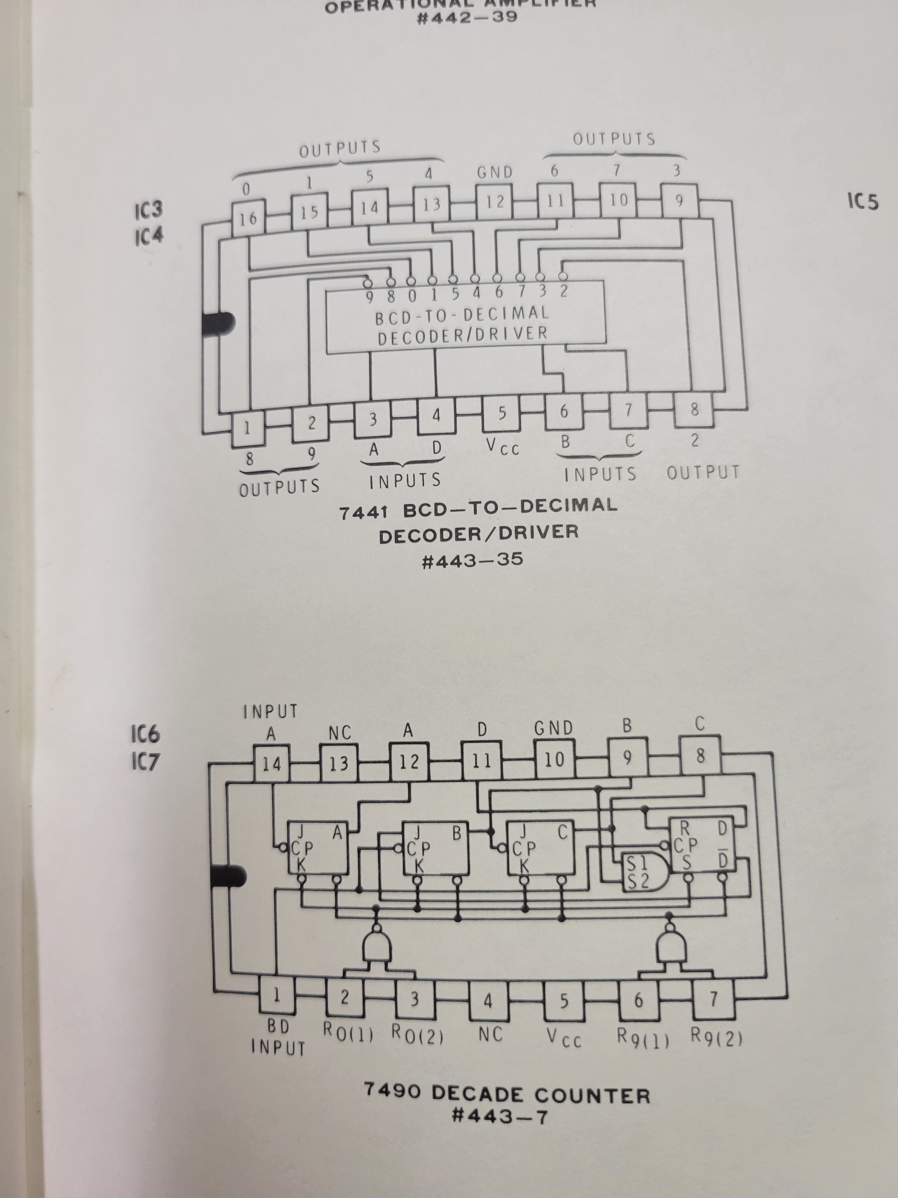
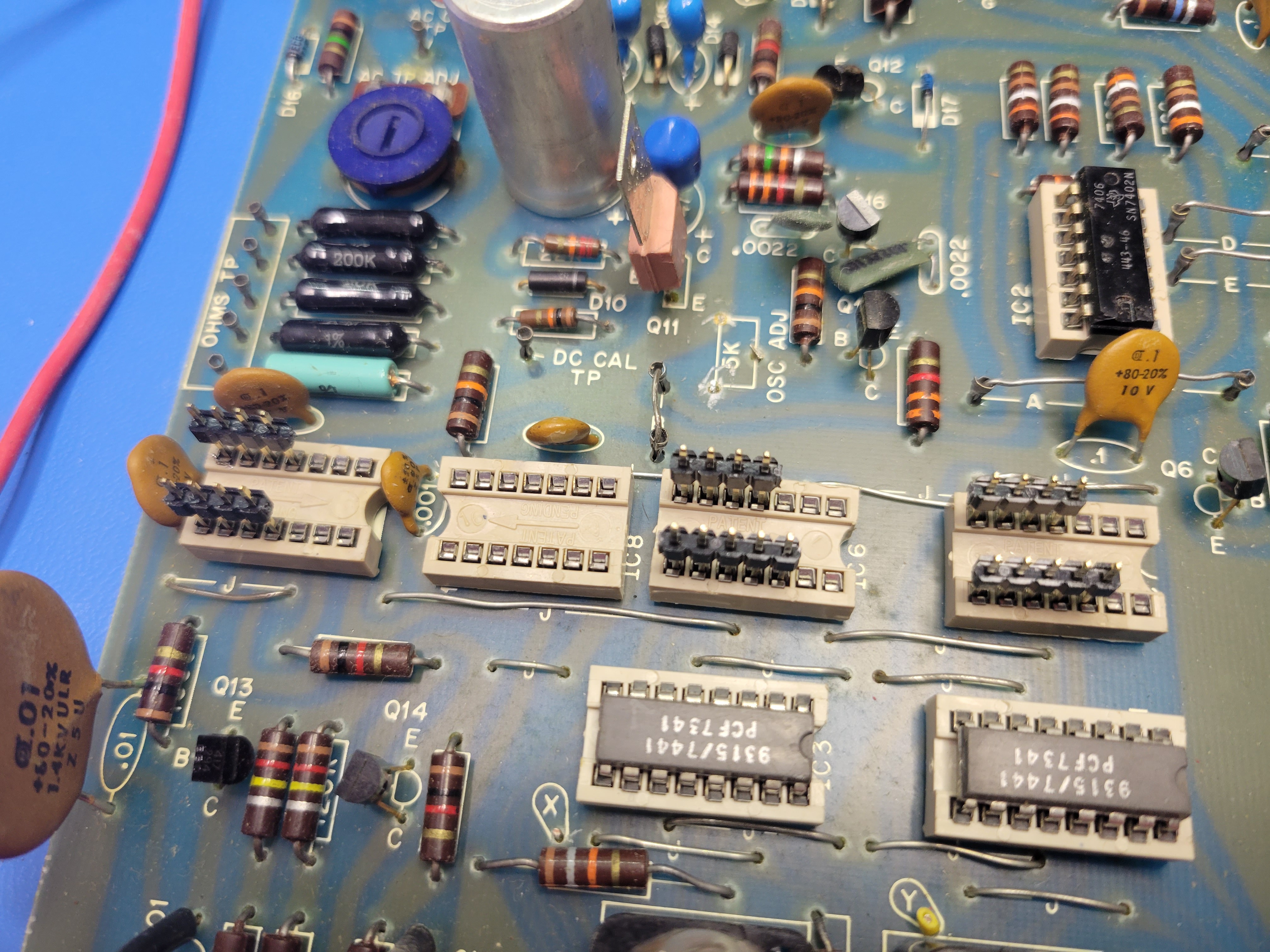
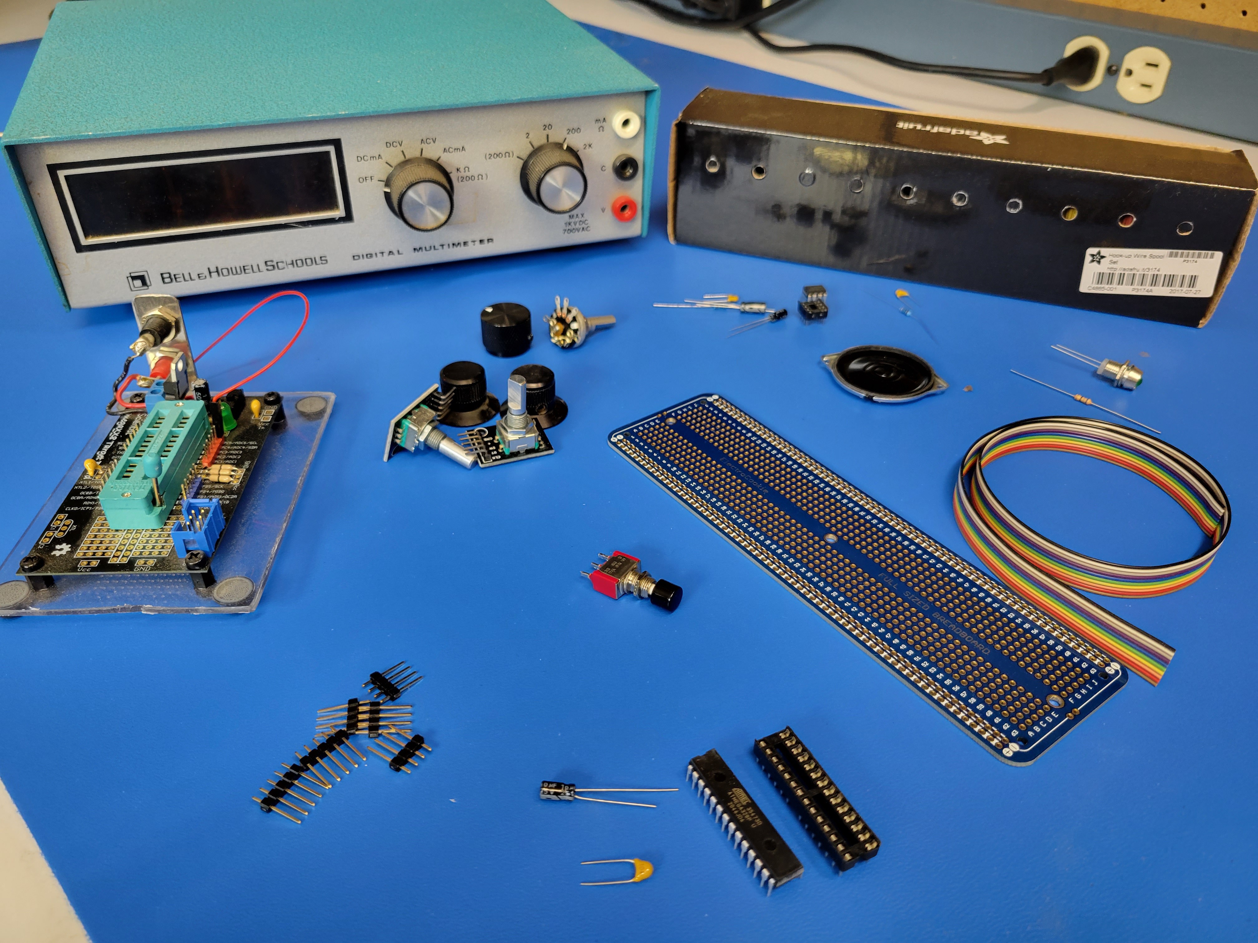
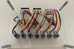
- It recycles: It's fun reusing old parts and technology. Besides being "the right thing to do" for reasons we already know, "Recycling" requires disassembly and reverse engineering. It's fun to take things apart and figure how they work. I often learn things applicable to other projects in the process. "Recycling" also requires a different approach to design and implementation. It defines the space you are working in and presents challenges that force you to look at projects from a different perspective
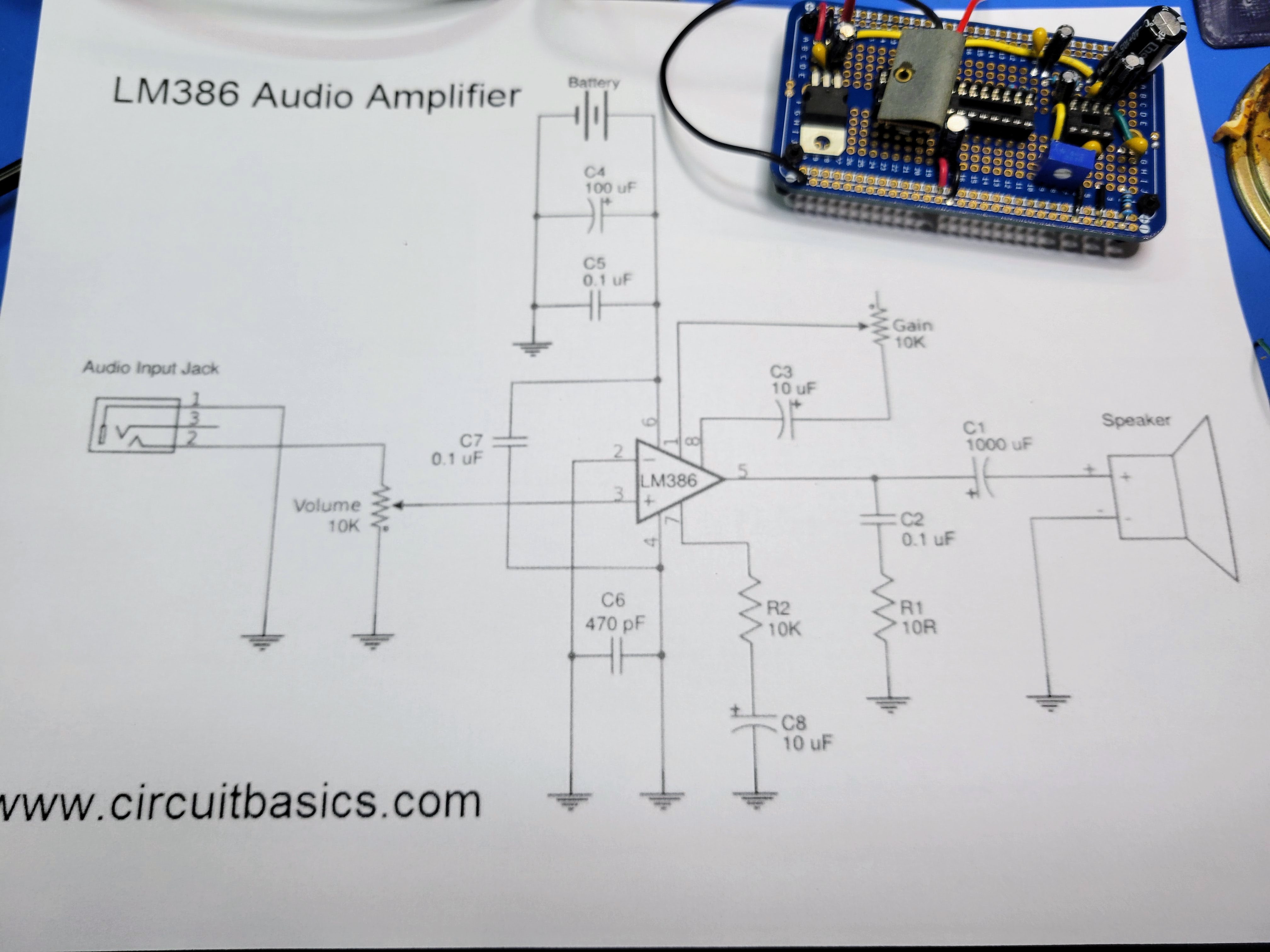
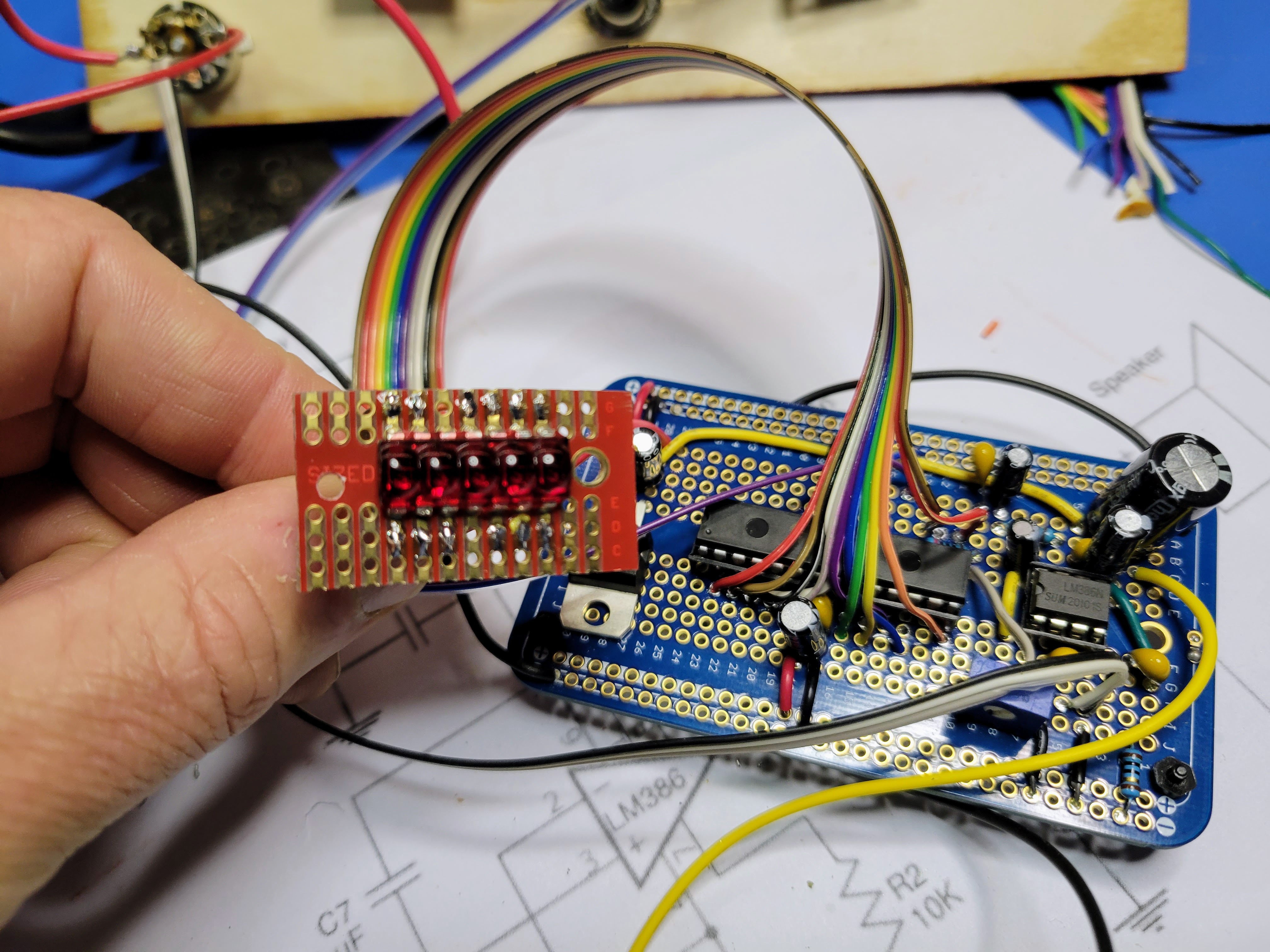
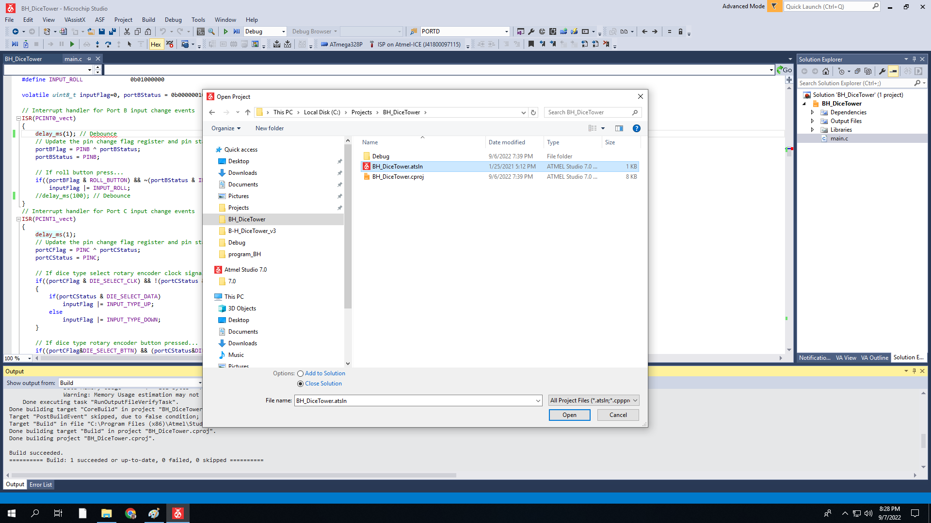
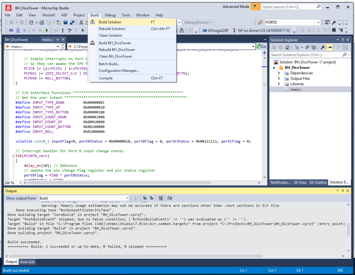
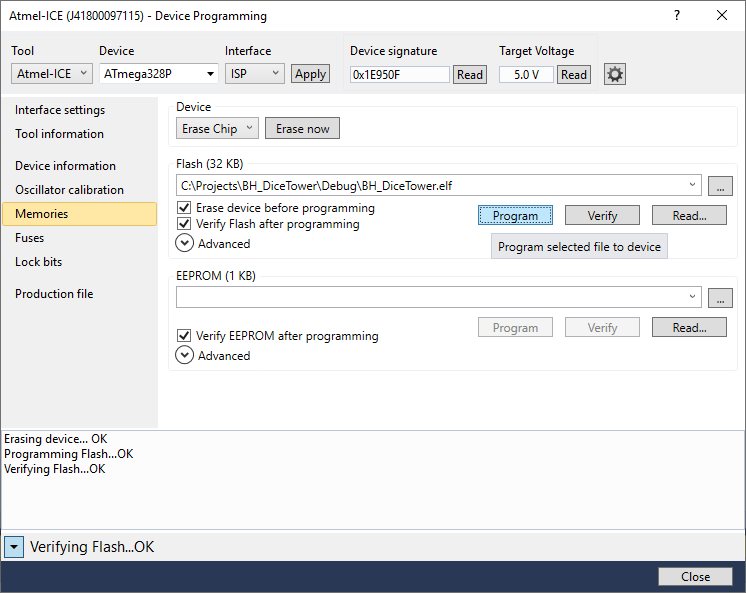
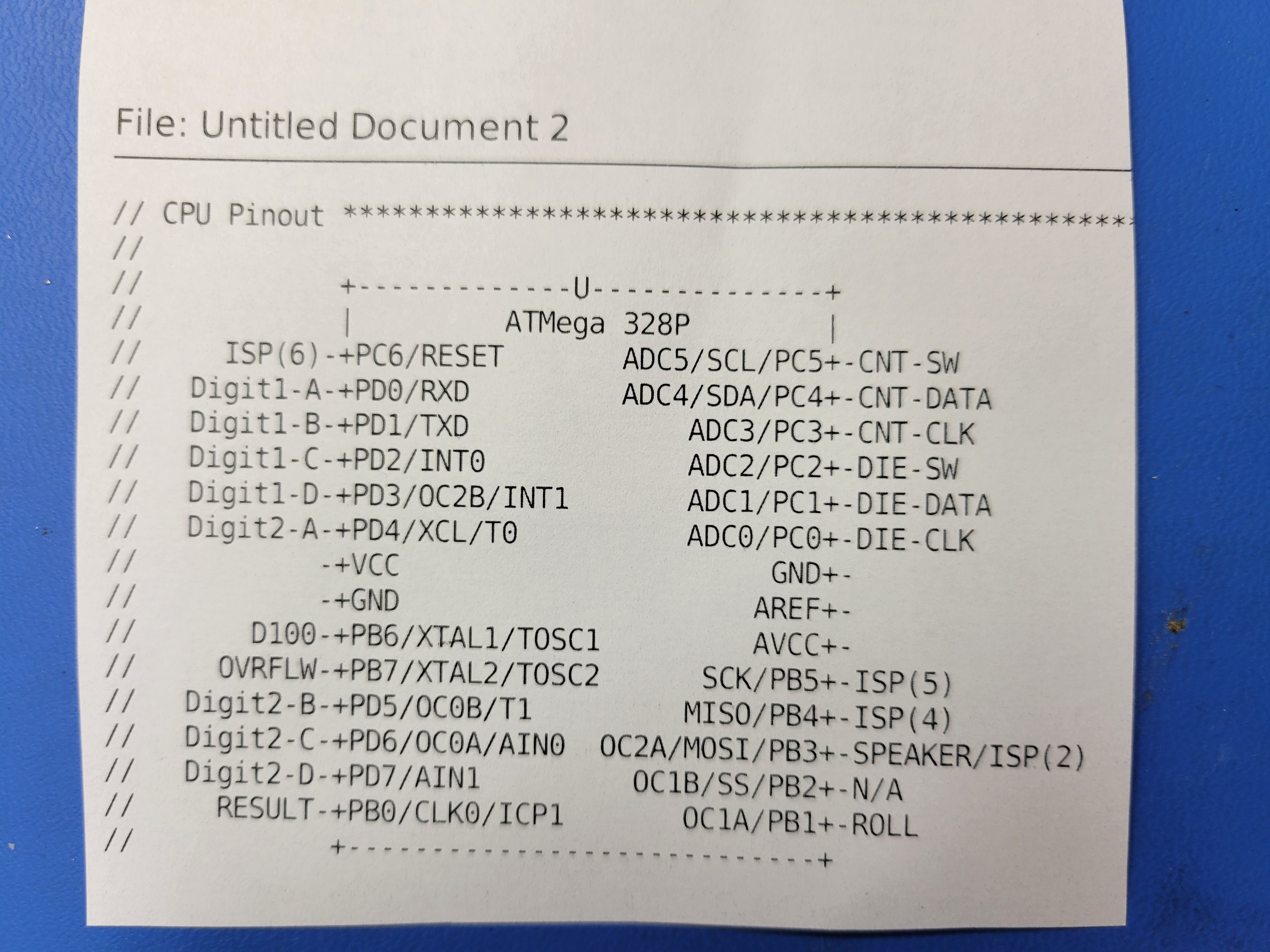
- There's a micro-controller: A project just isn't fun unless there's a micro-controller and some software to write, download, debug, and iterate
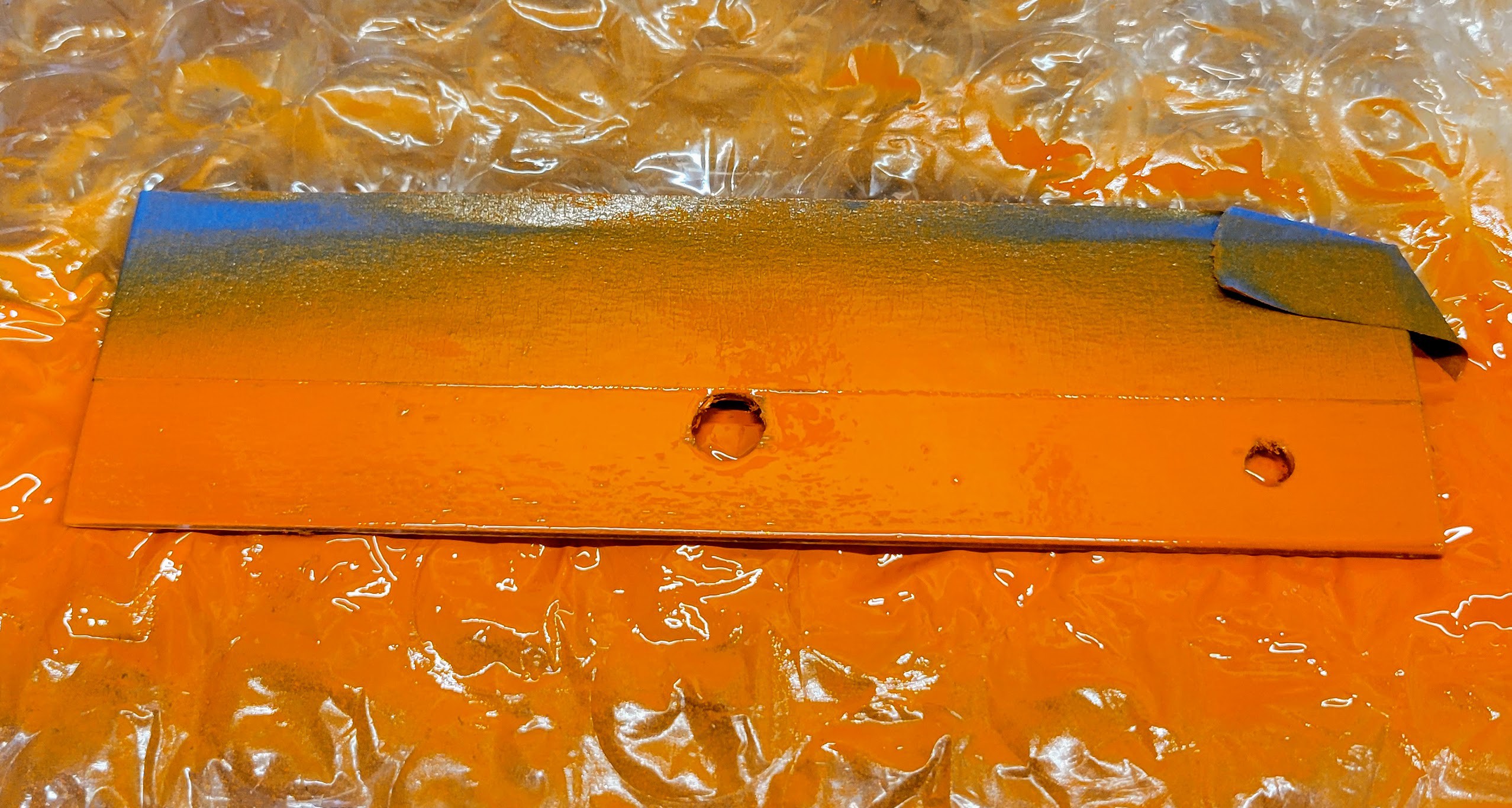
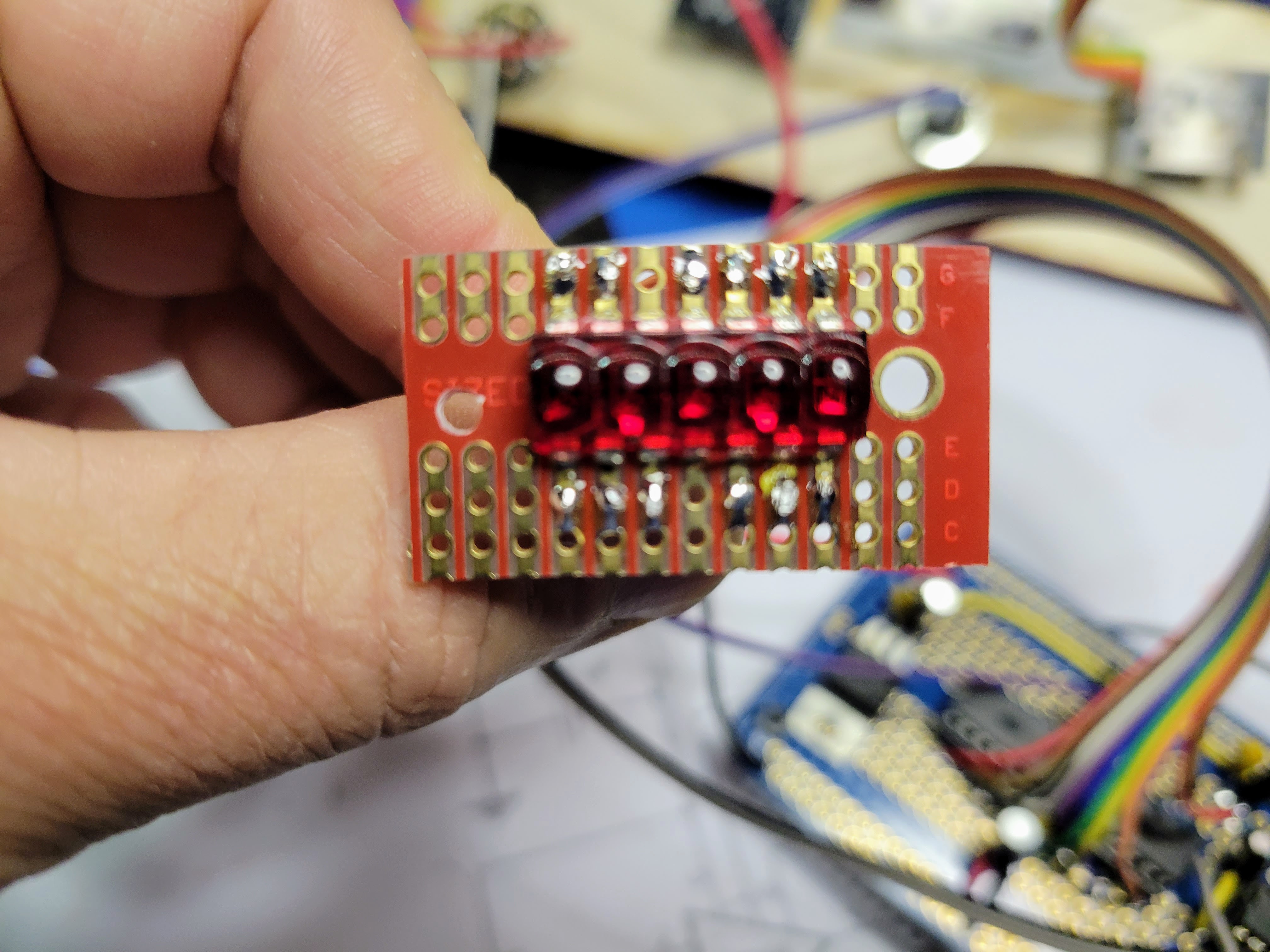
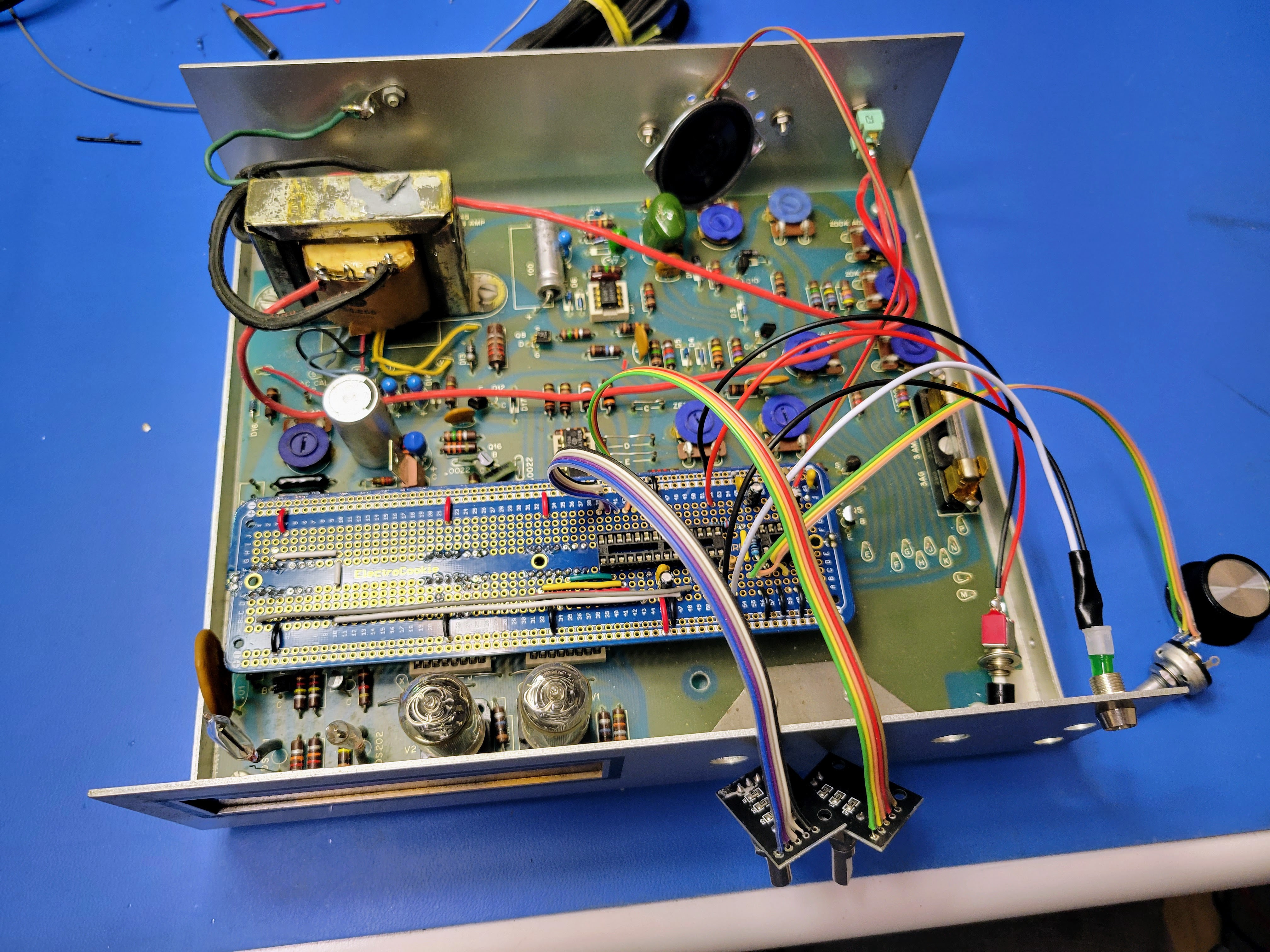
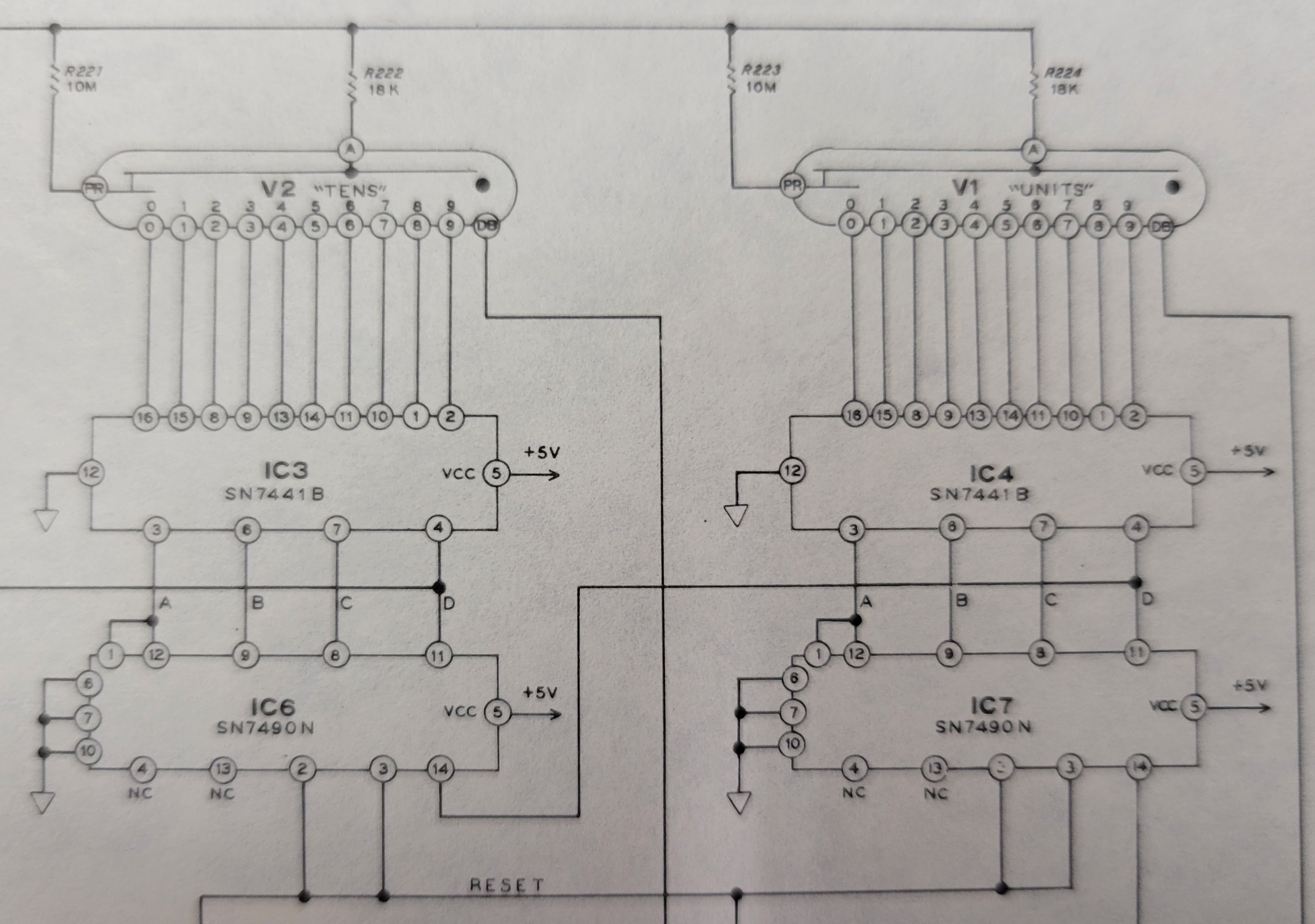
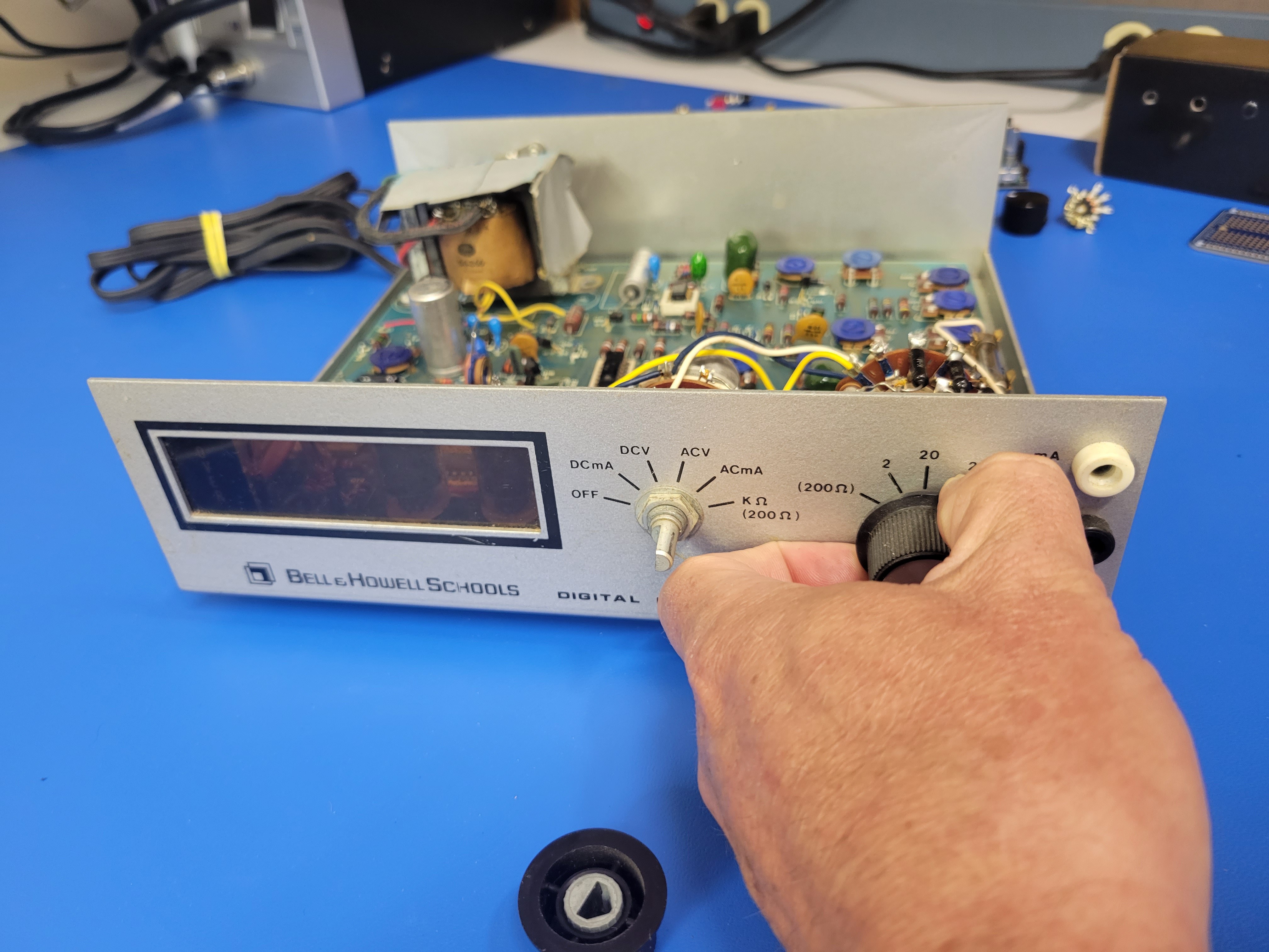
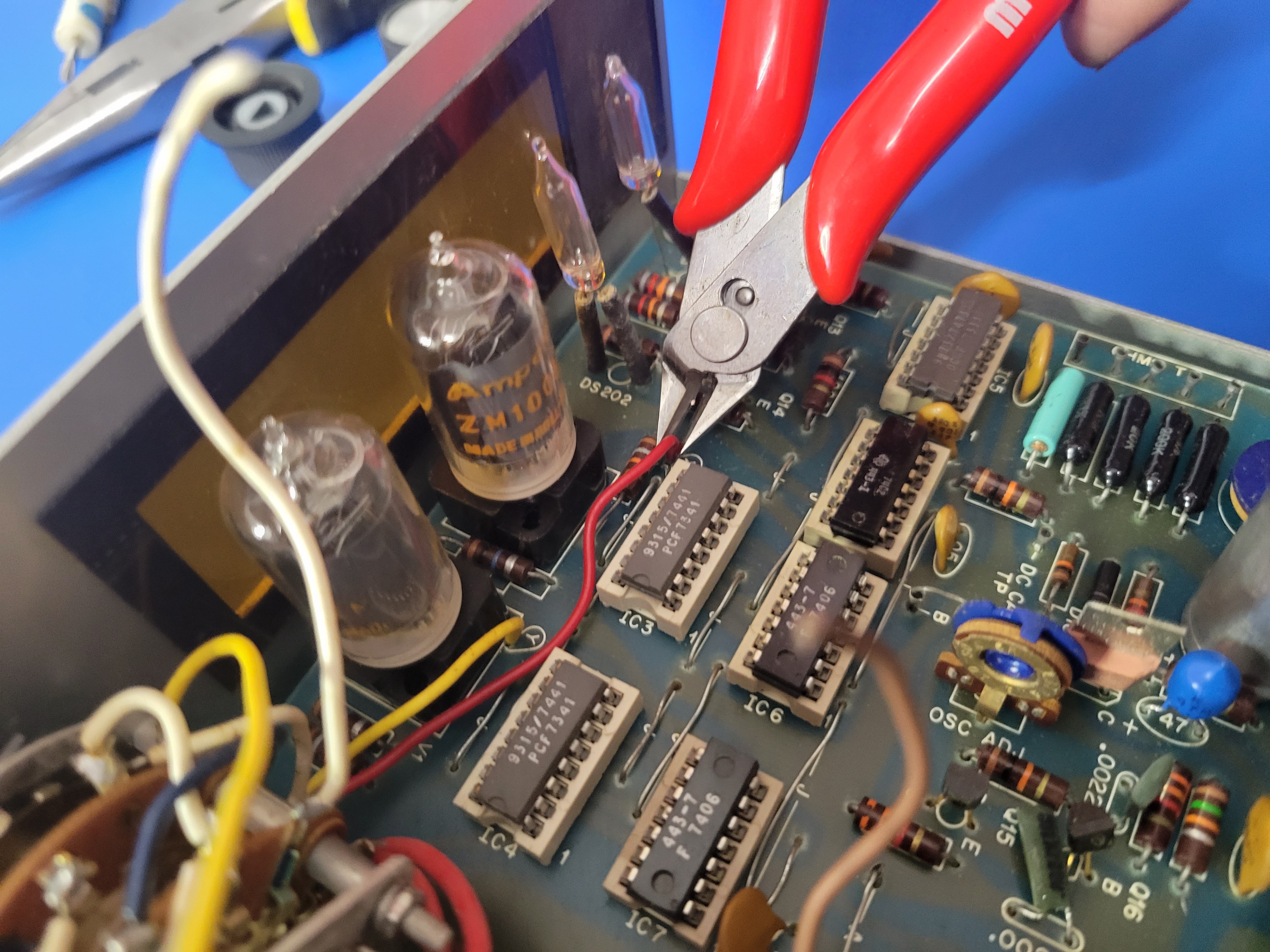
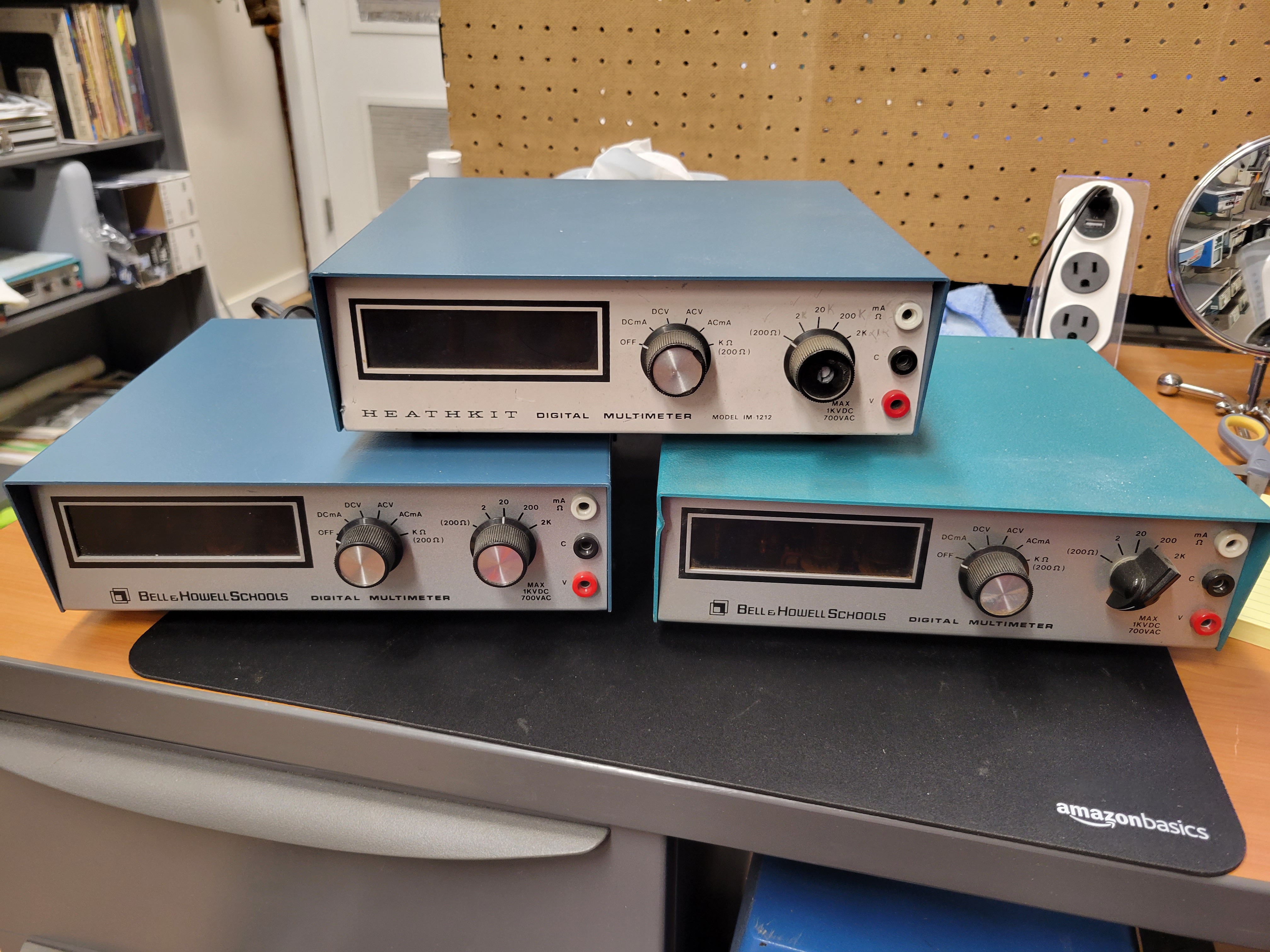
- It's retro-cool without the retro software development: I love the old display technologies, the classic panel mount switches/dials/buttons, wrinkle paint, "lab equipment" blue, and sheet metal cases. I also appreciate the TTL logic IC's and big through-hole parts on PCBs. They simplify reverse engineering, hardware prototyping, and the tools/skills required to do it. However, I'm not a big fan of antiquated software development environments and code libraries. I prefer to stay current, thus the resto-mod approach using AVR micro-controllers
- It enables vision impaired players to experience table top gaming in a new independent way. After I started building and posting videos of these devices, I was contacted by a couple players. Each asked if I could build one for their significant other that was vision impaired. They each wanted to give their spouse a new independence at the game table that would improve their game experience
This is a ongoing project that encapsulates several pieces, I've posted logs that capture the new builds and features.
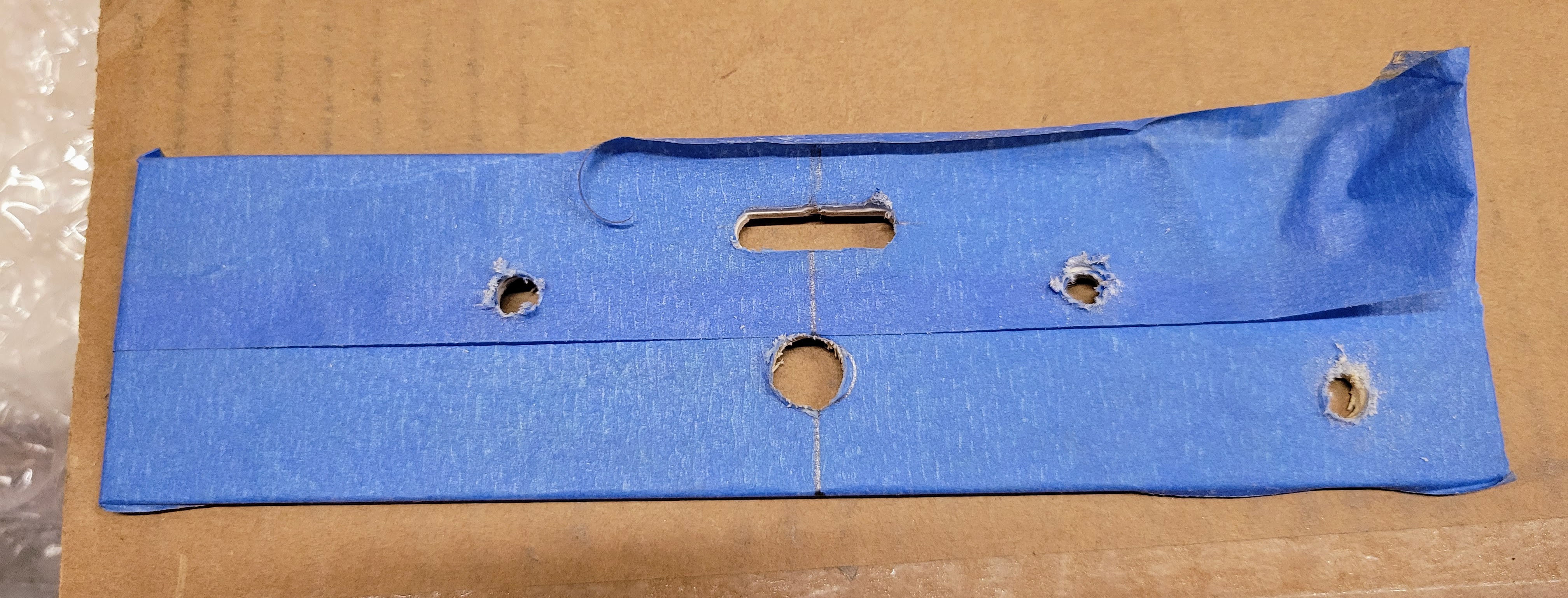
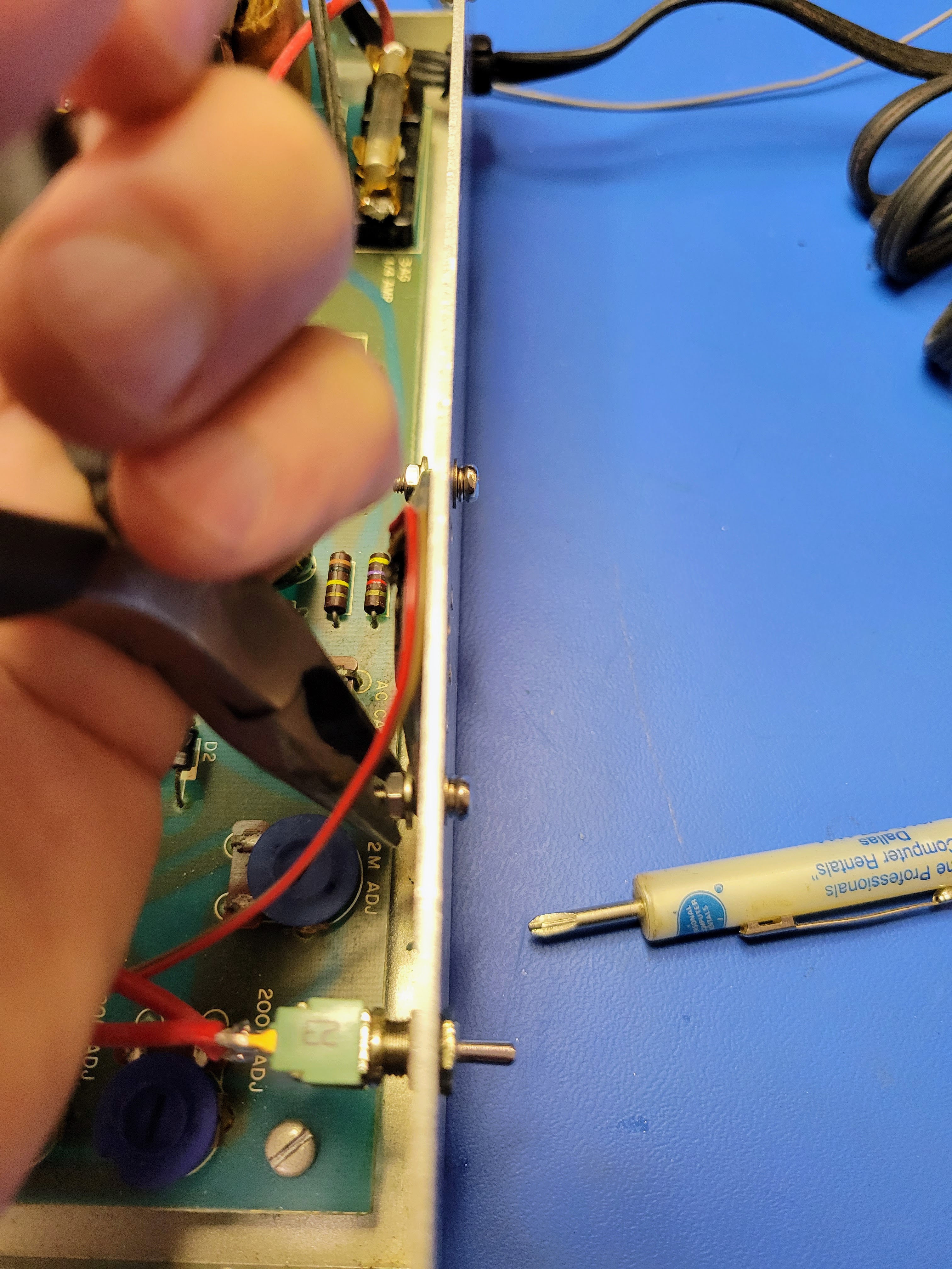
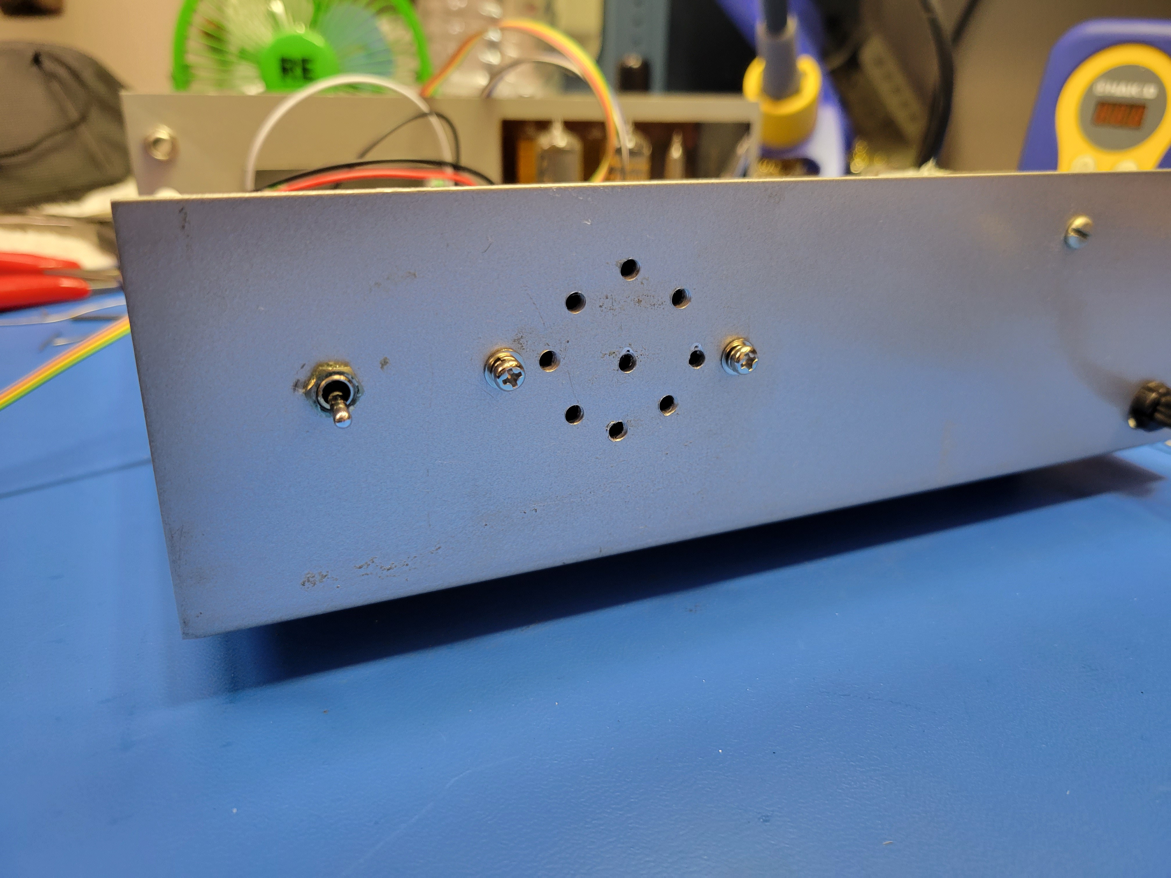
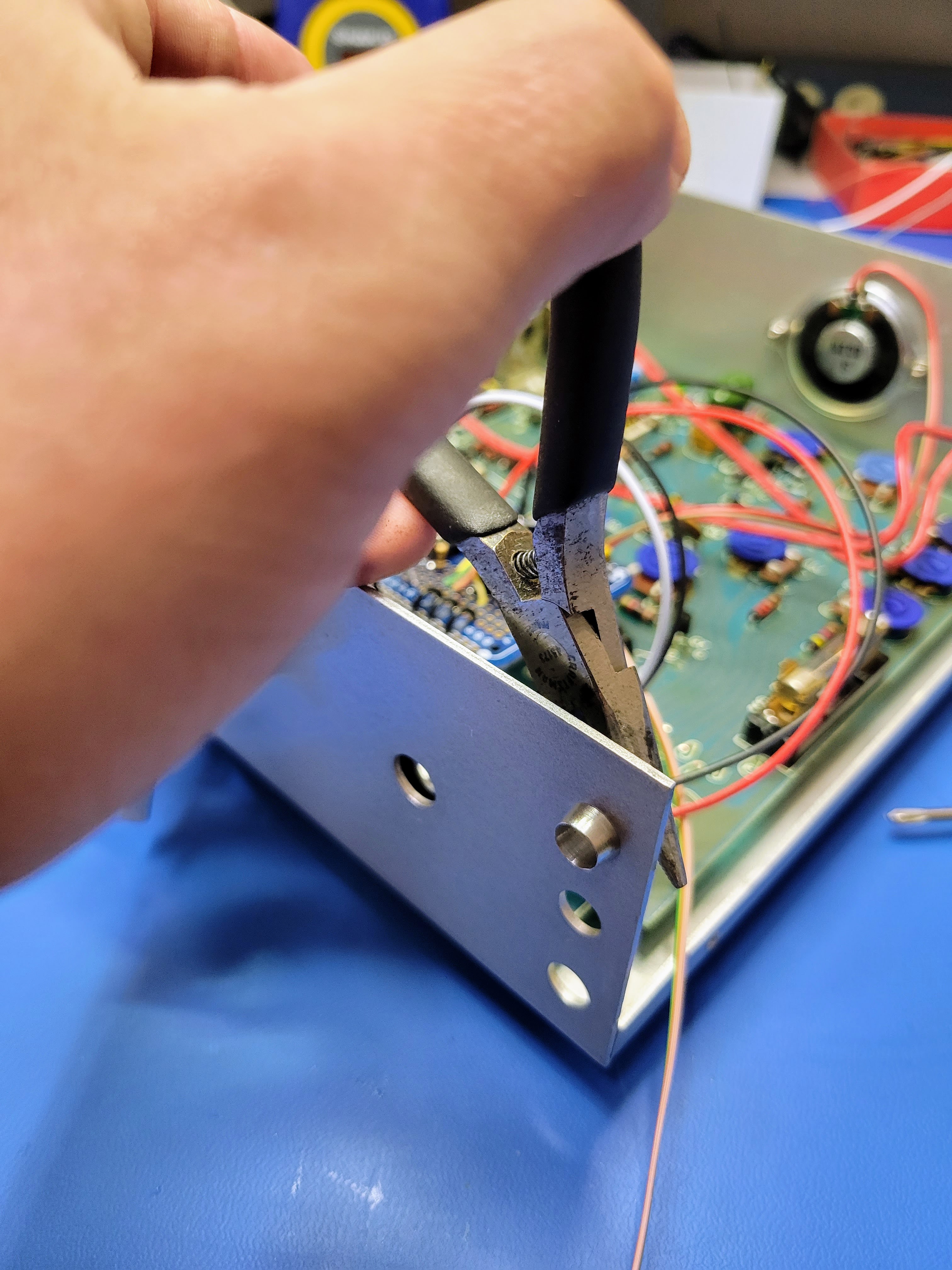
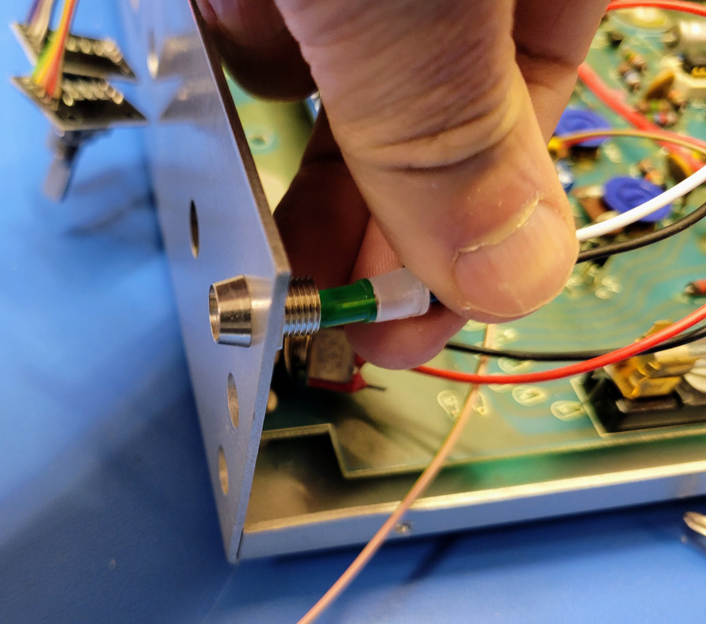
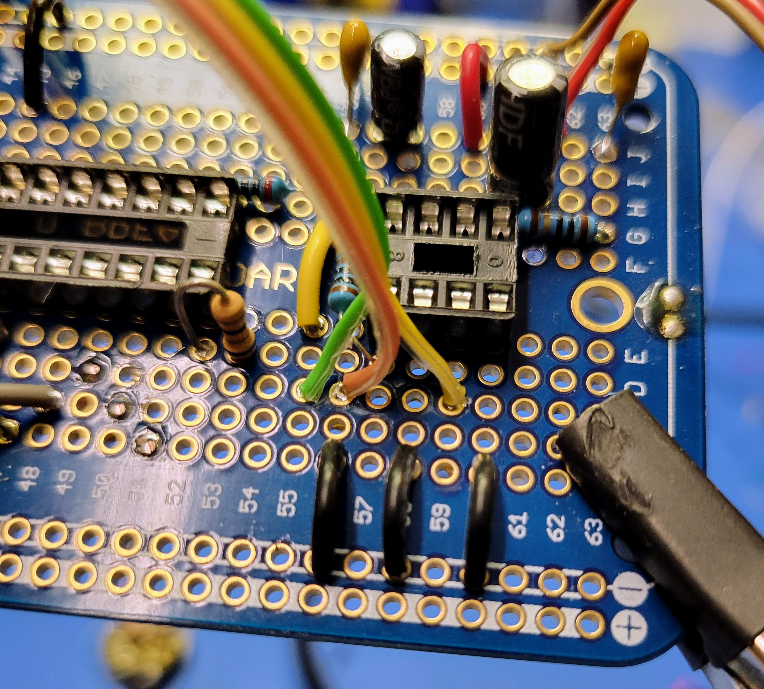
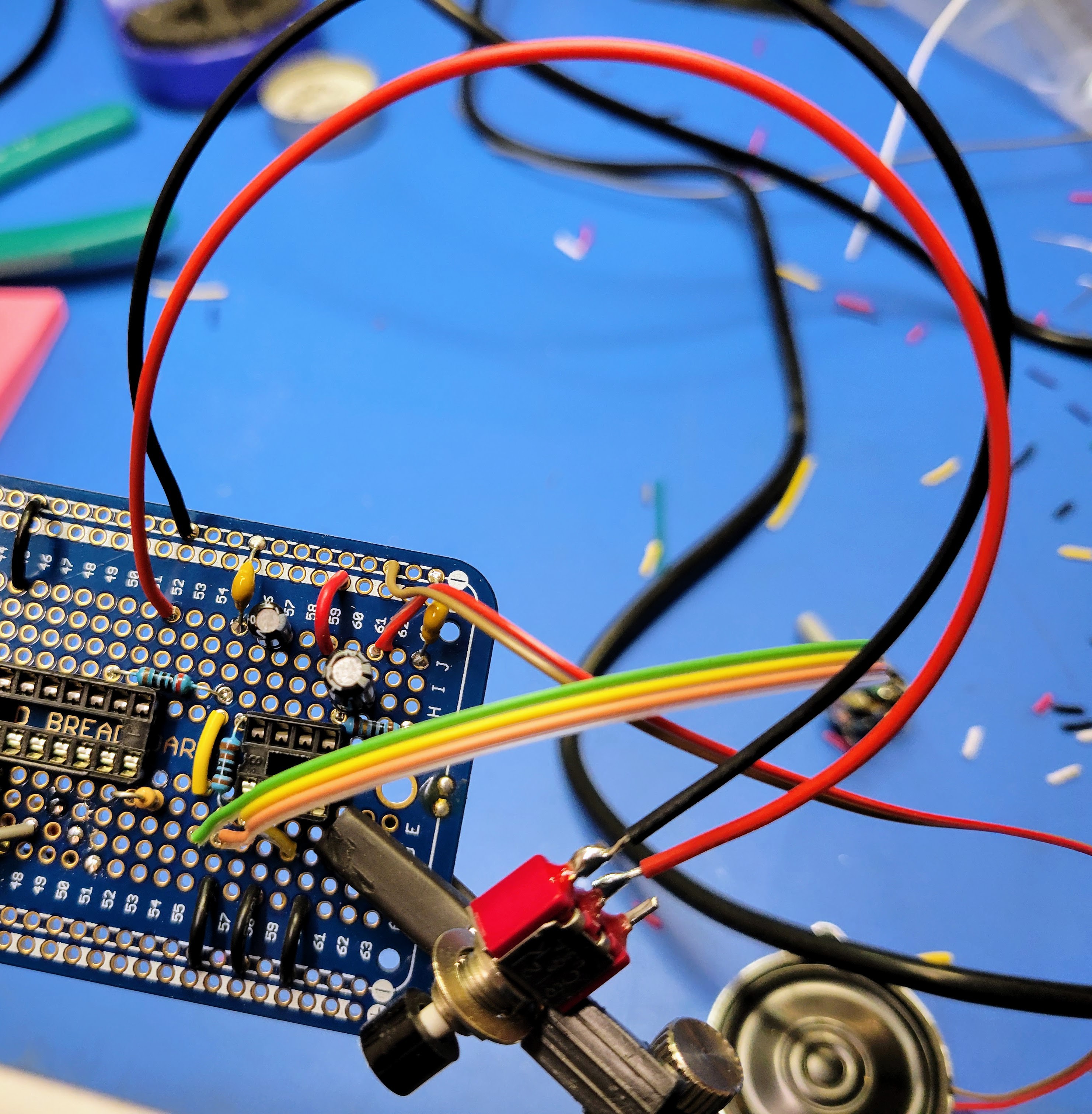
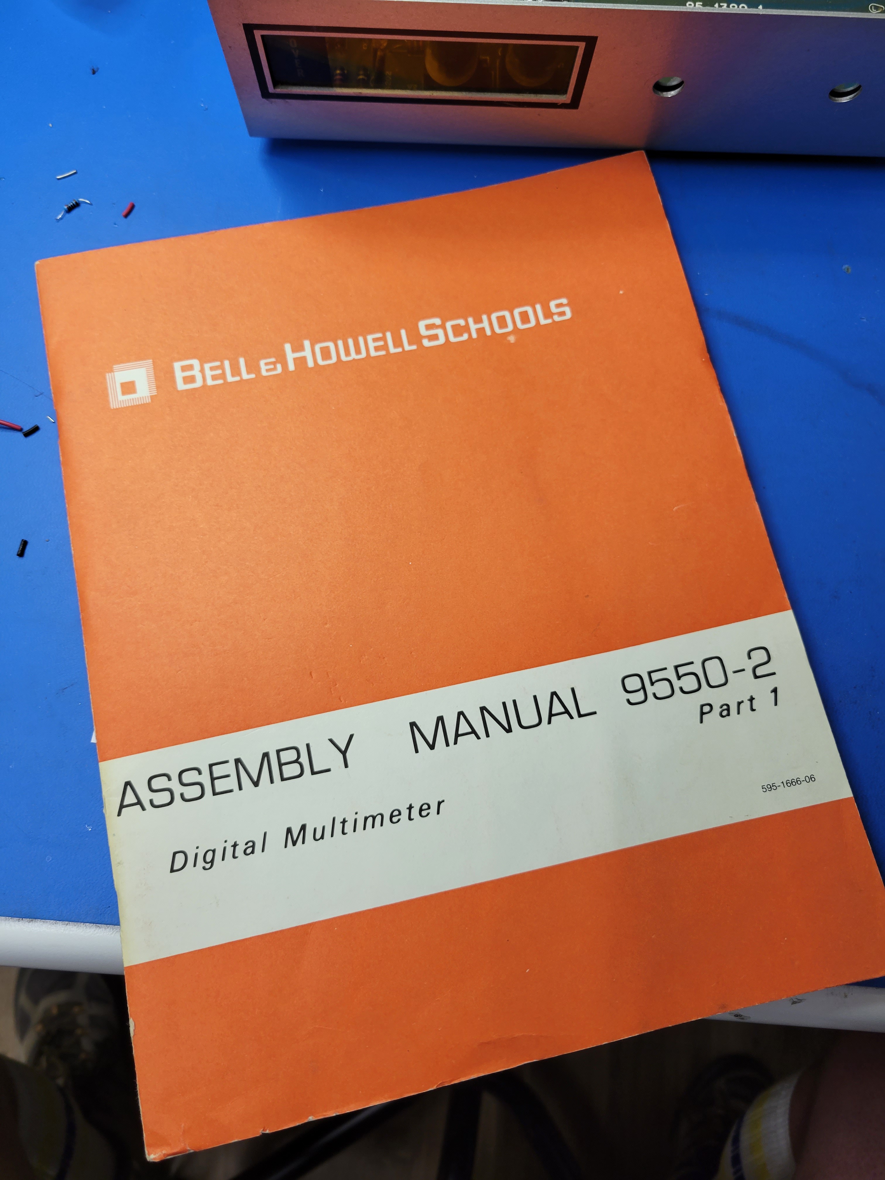
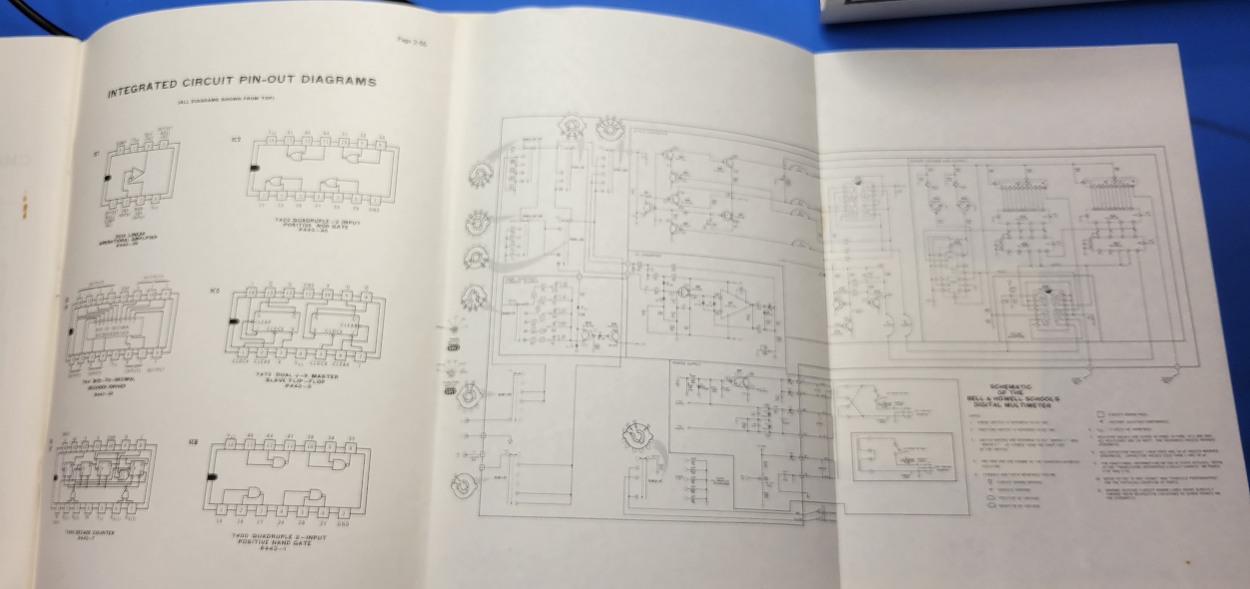
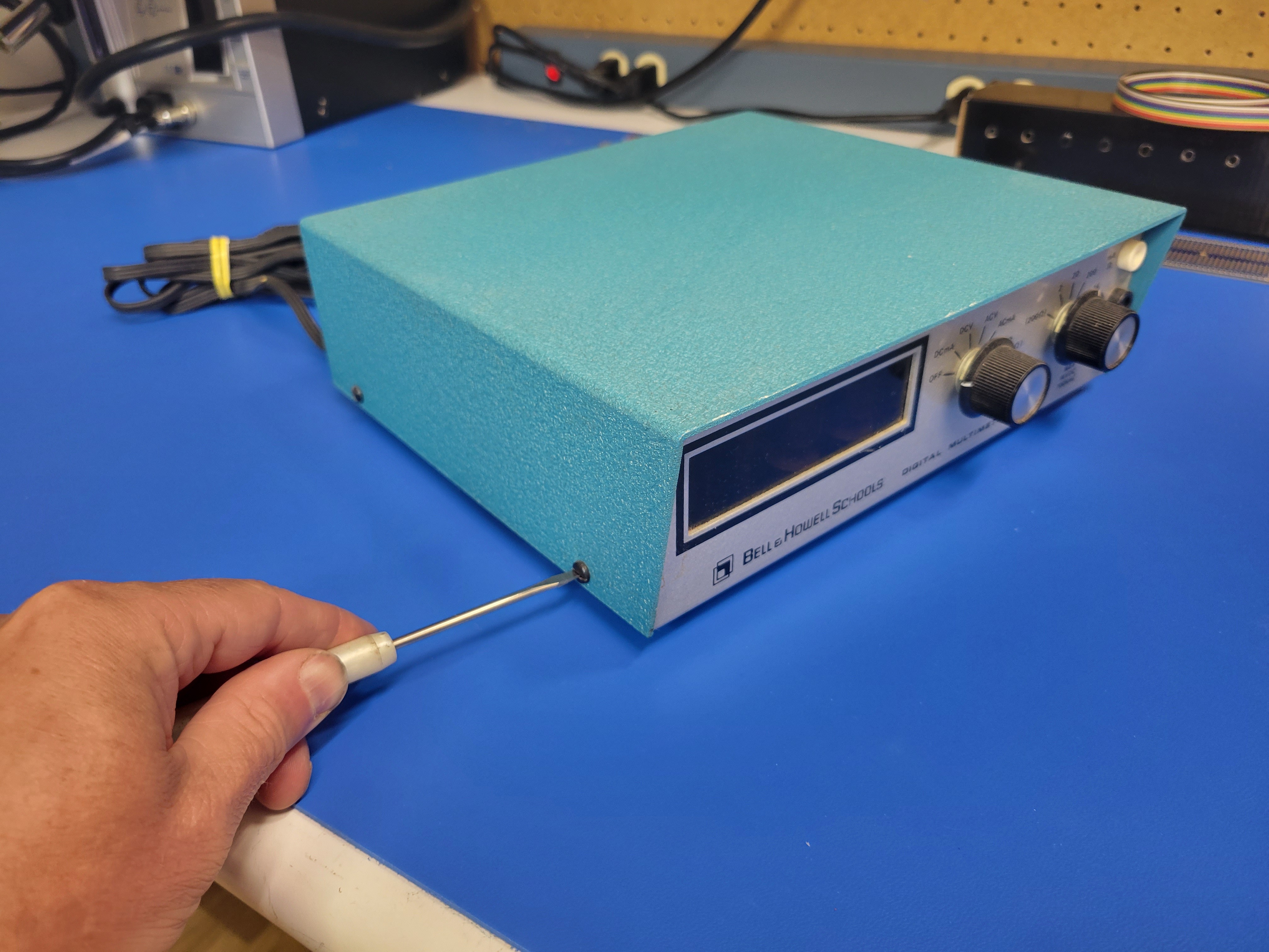
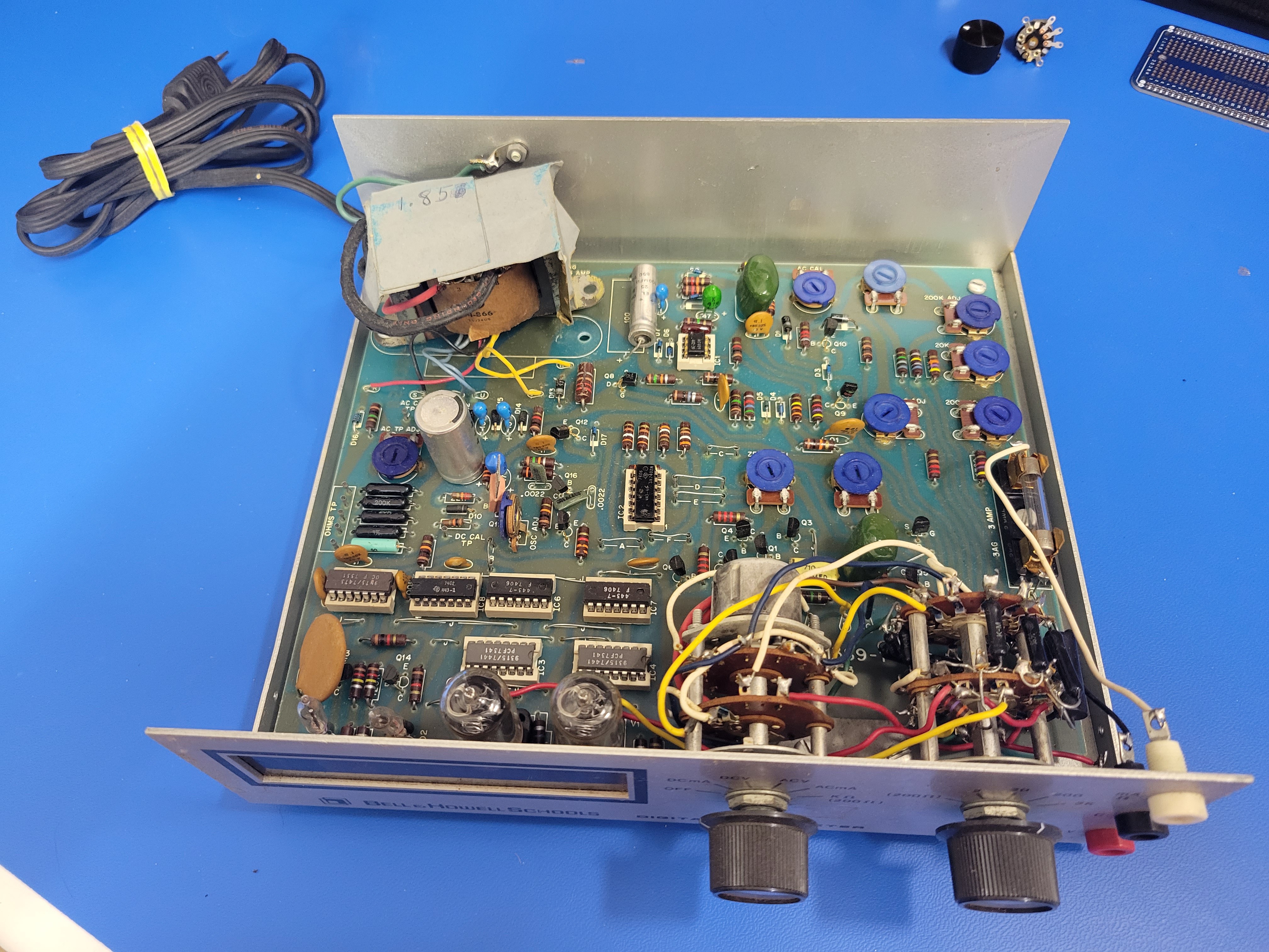
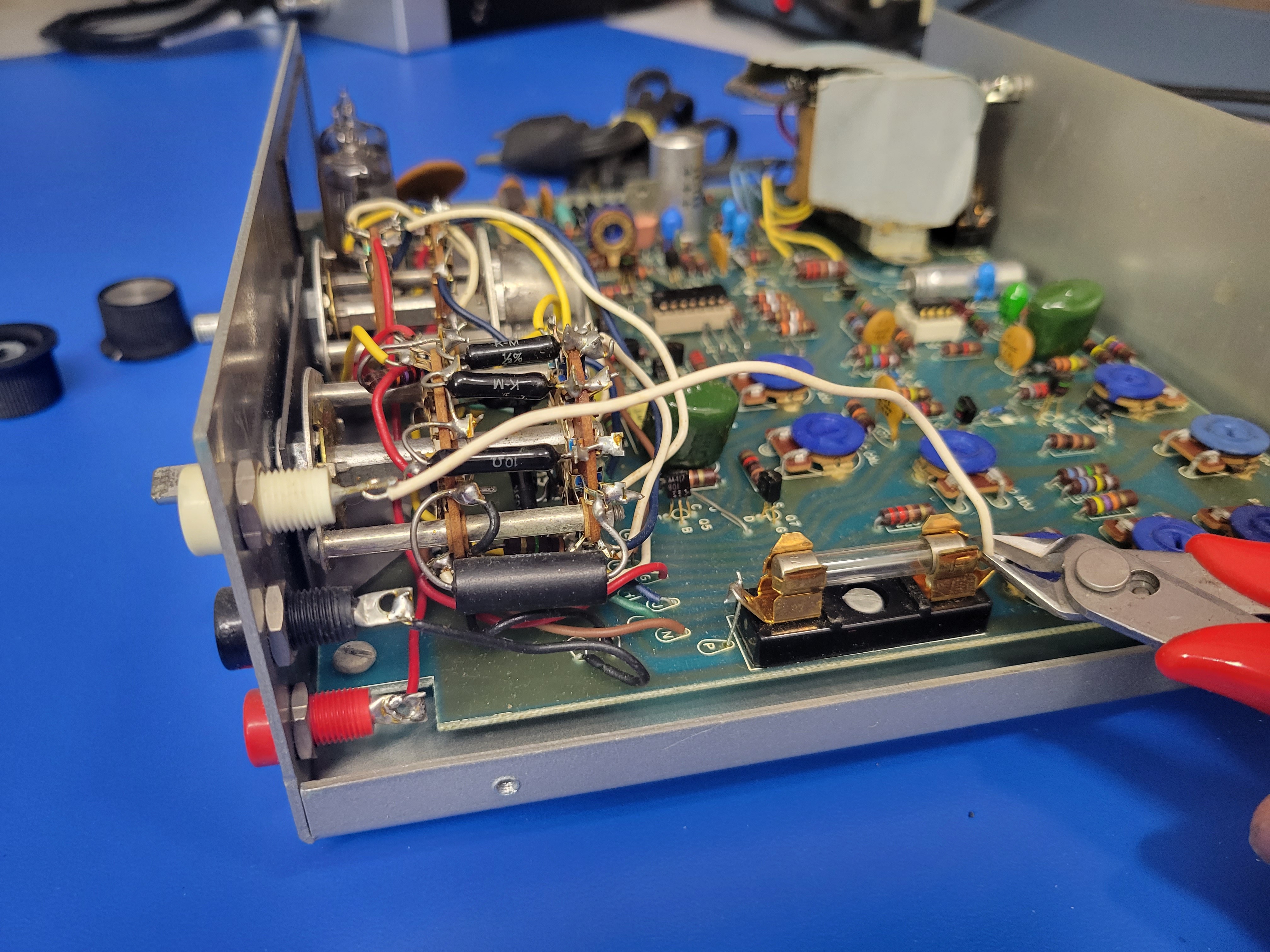
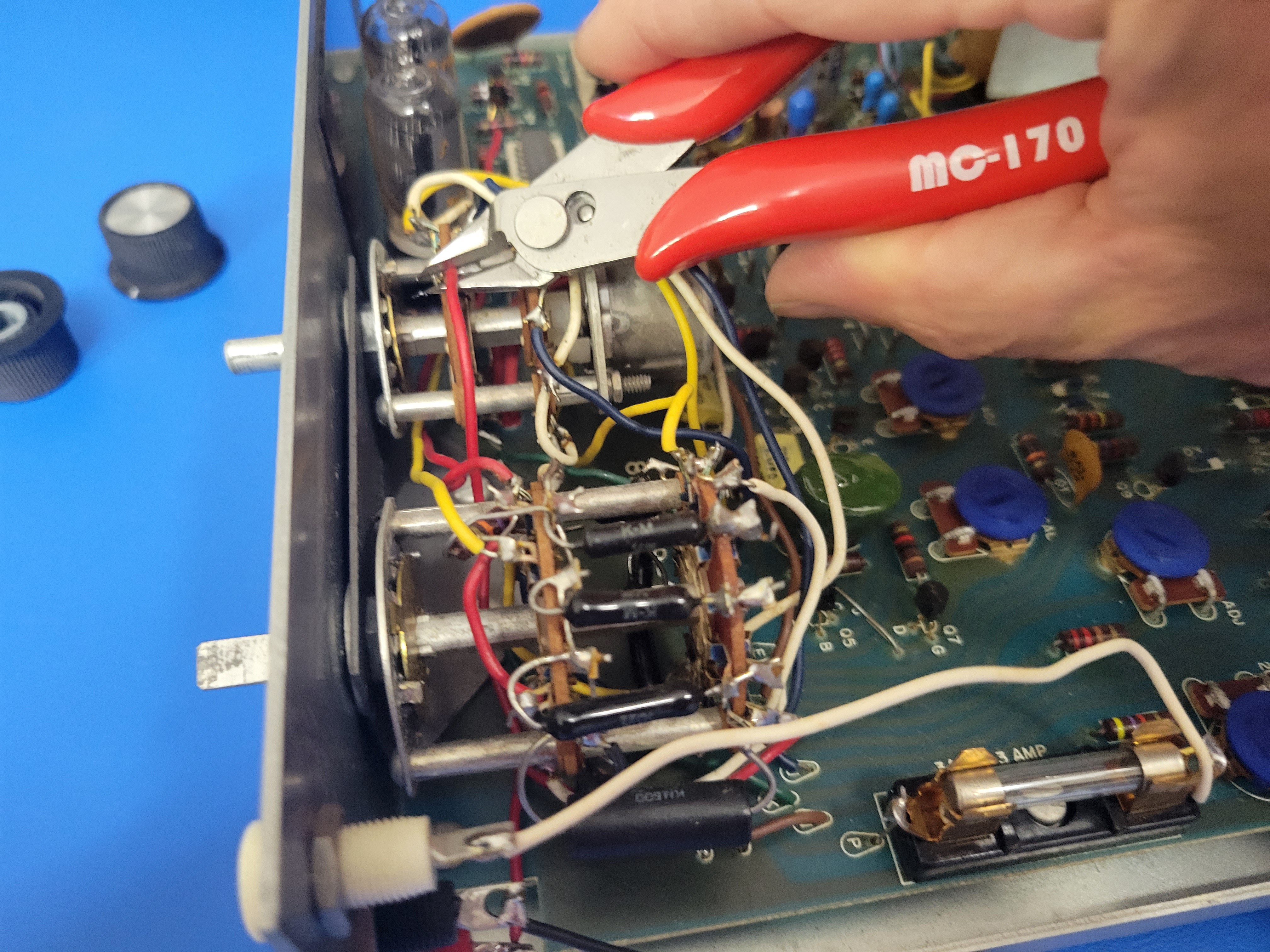
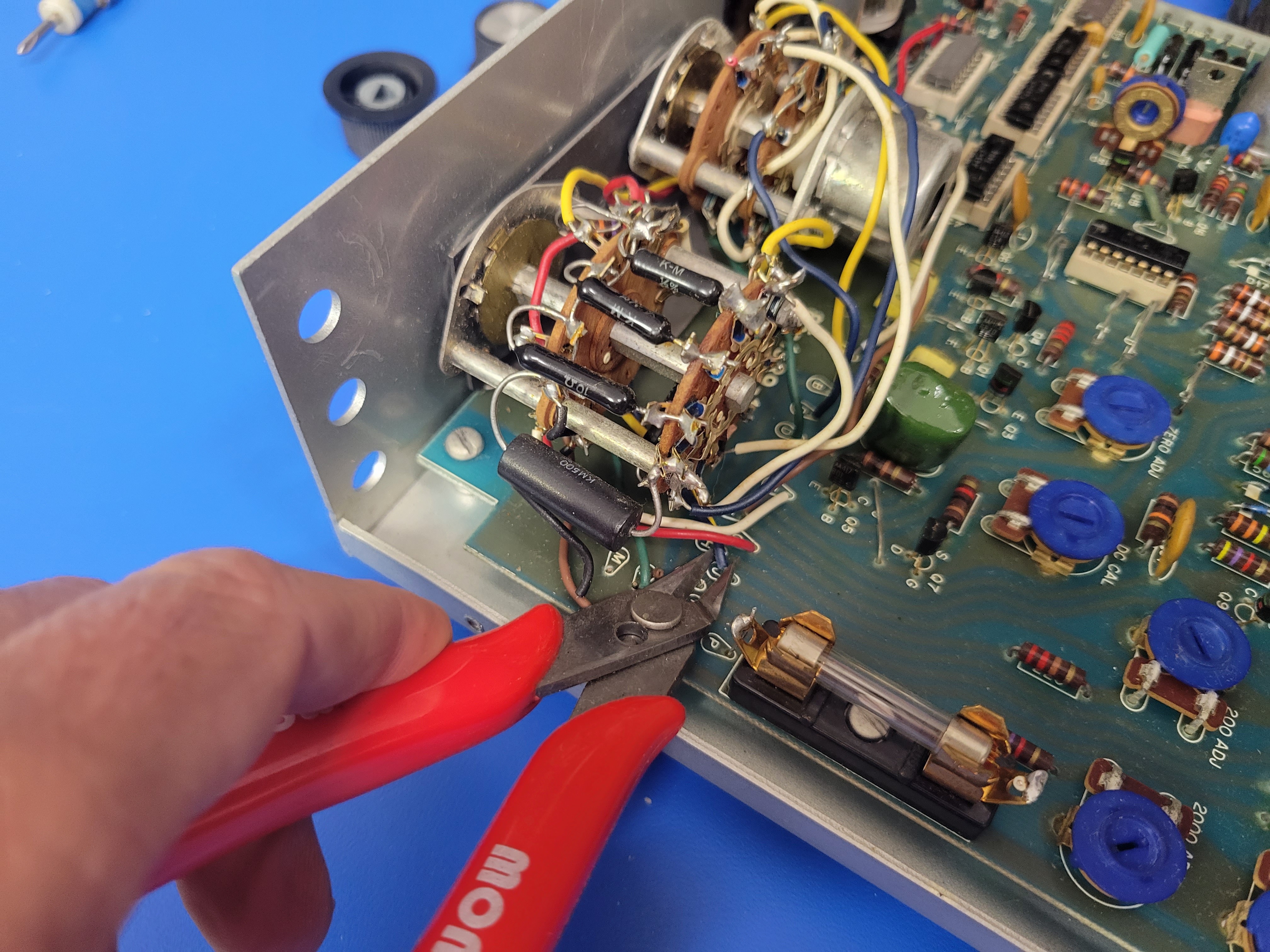
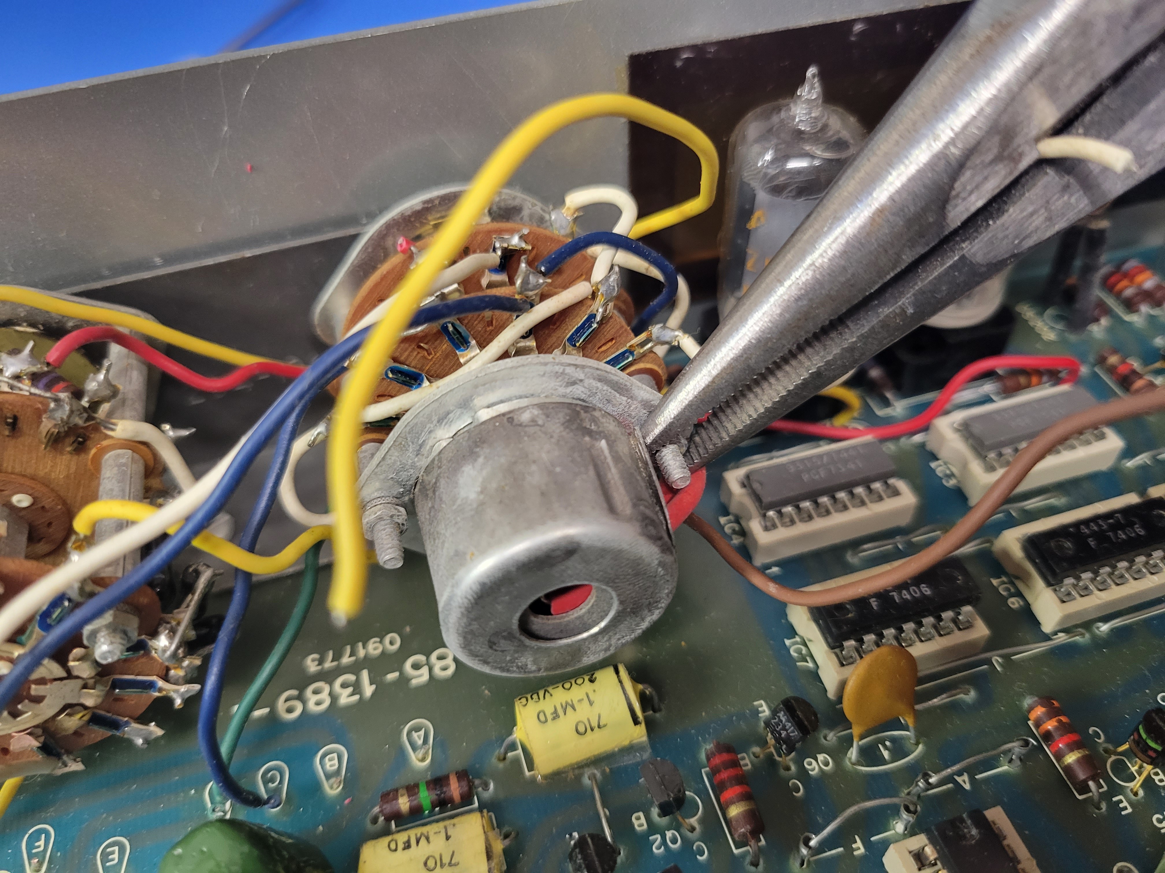
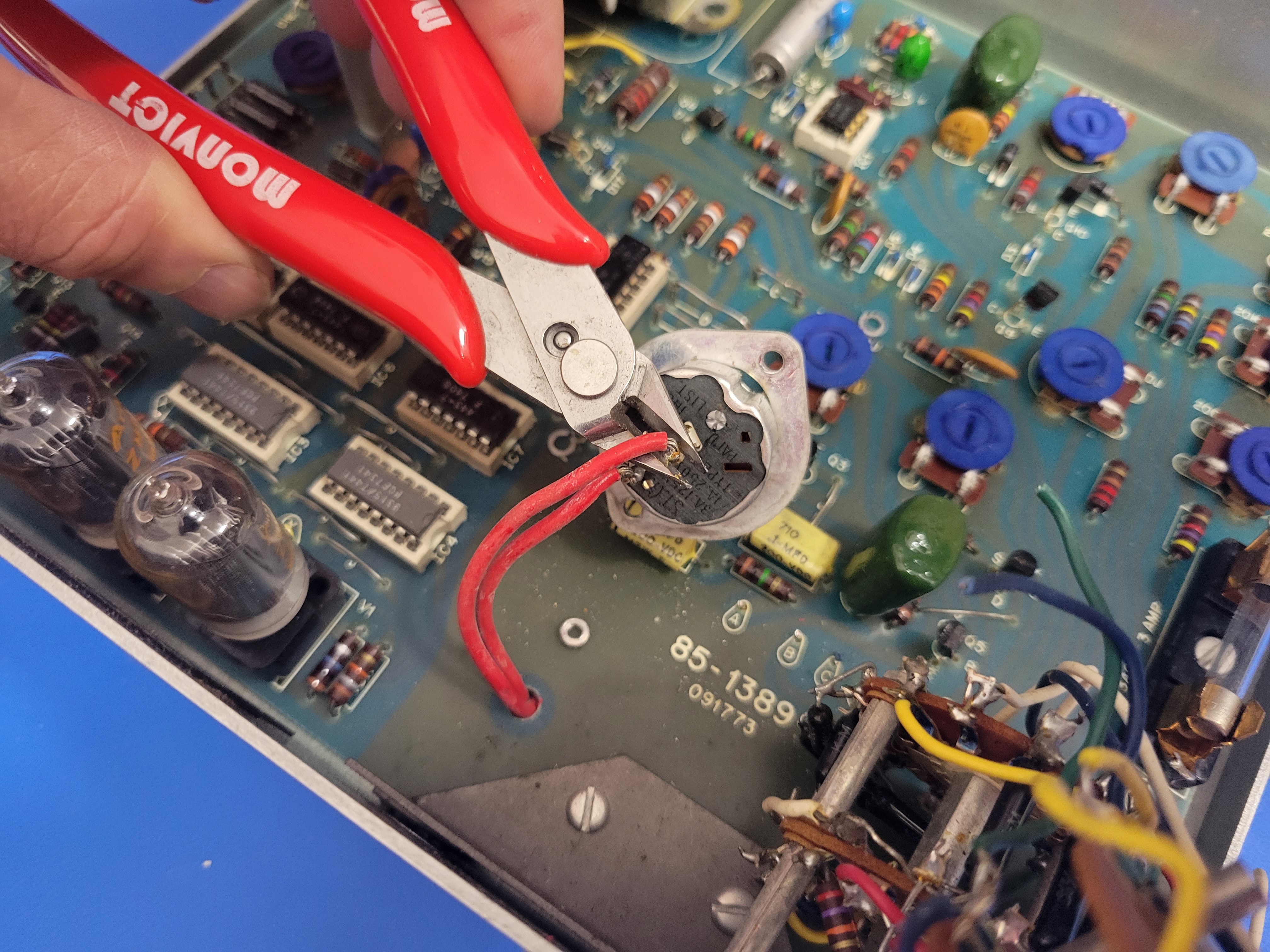
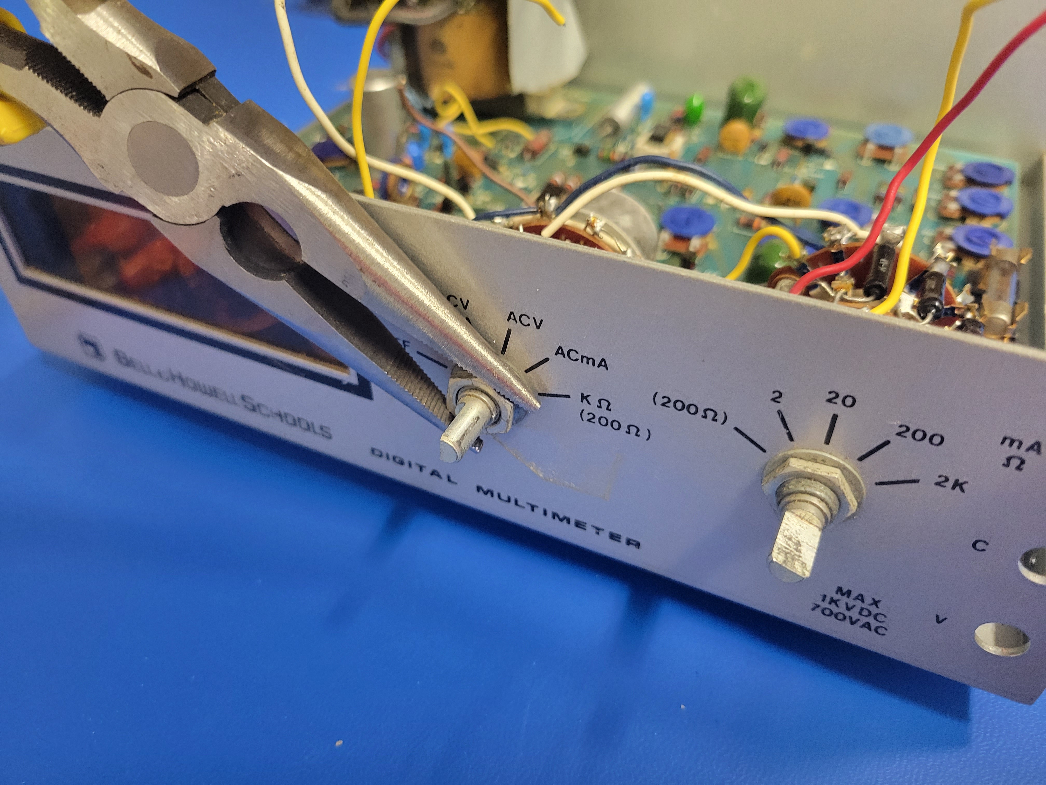
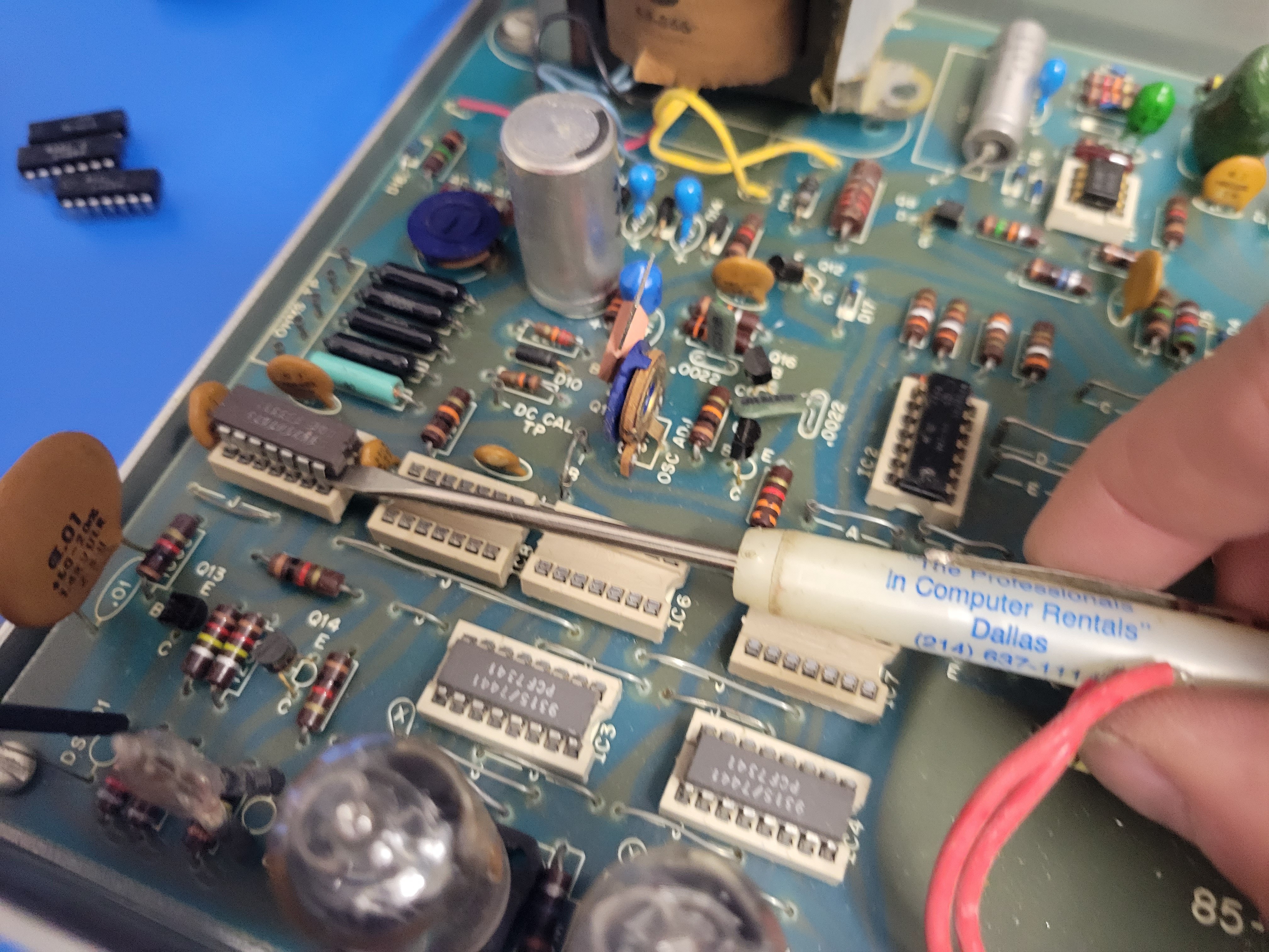
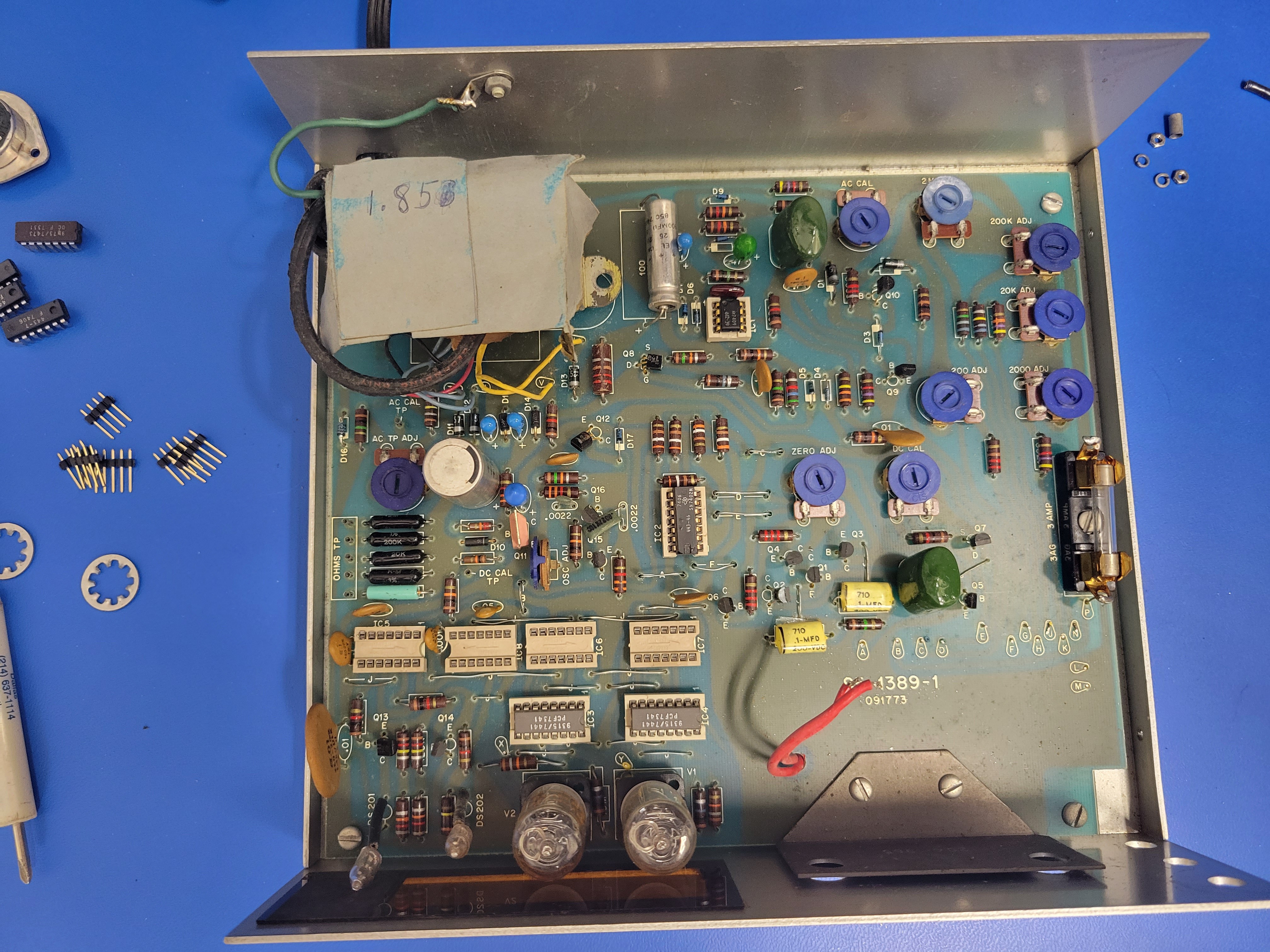
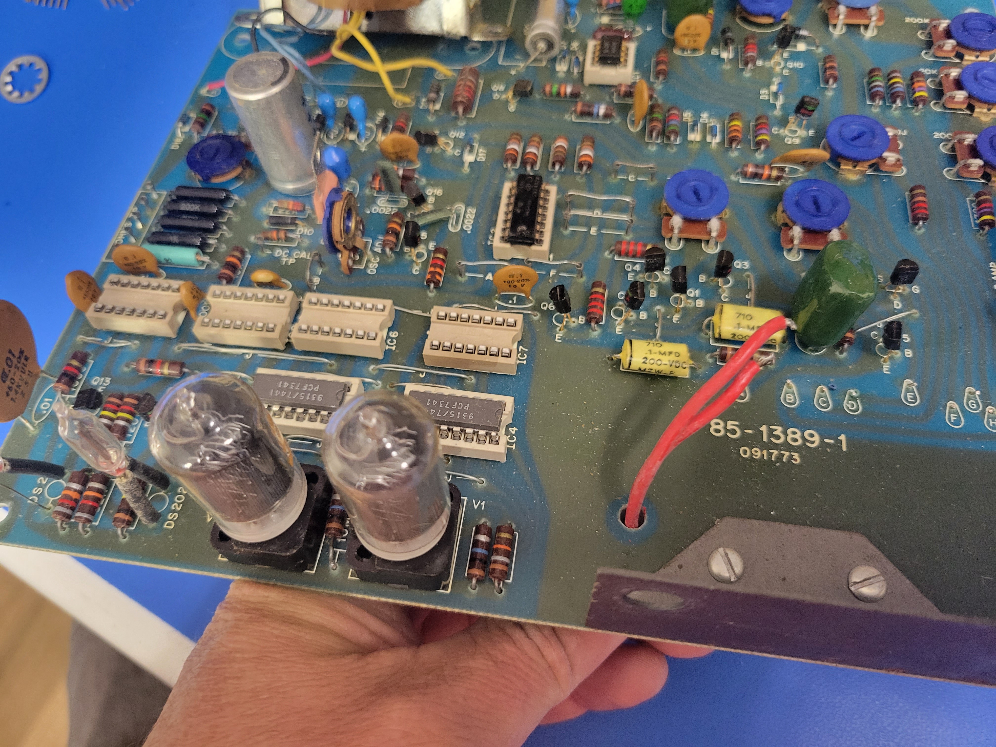
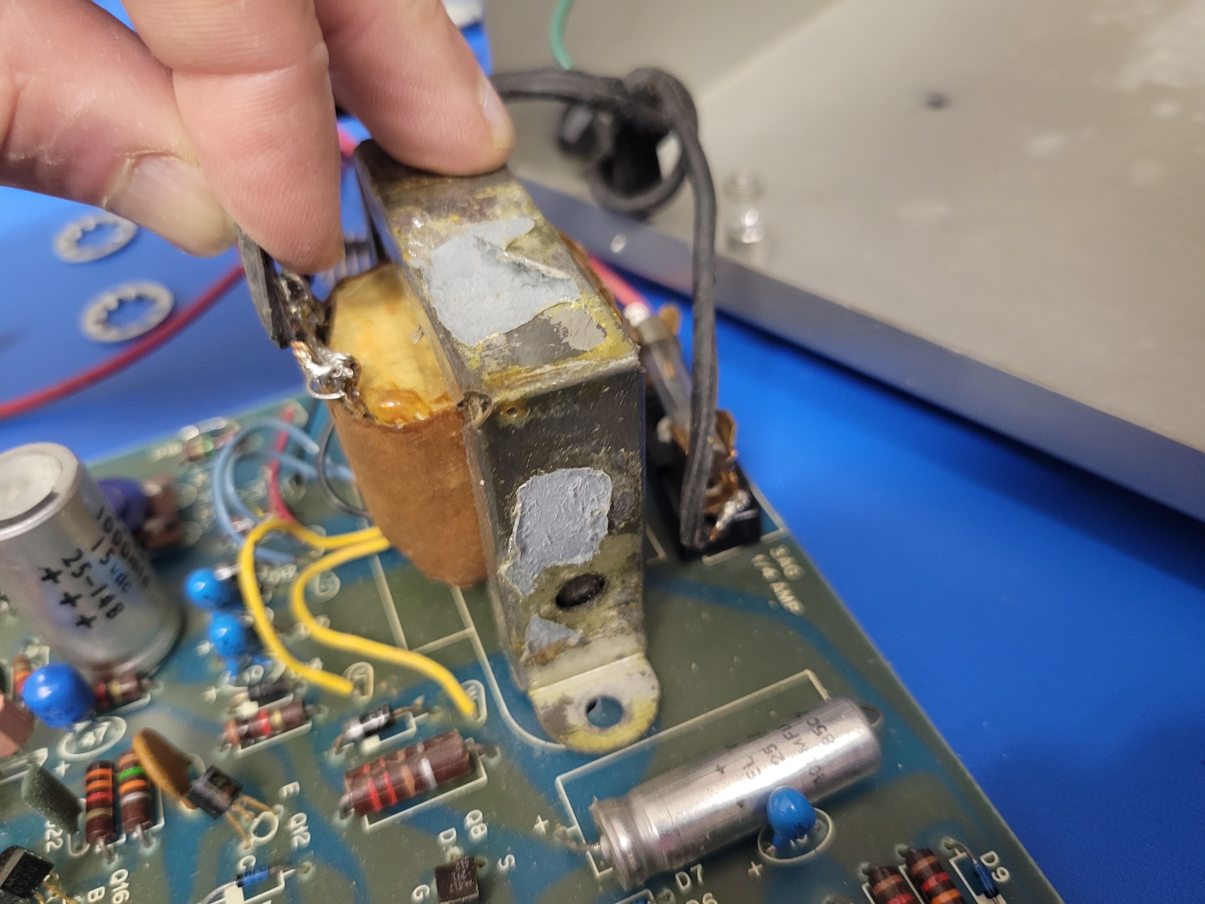
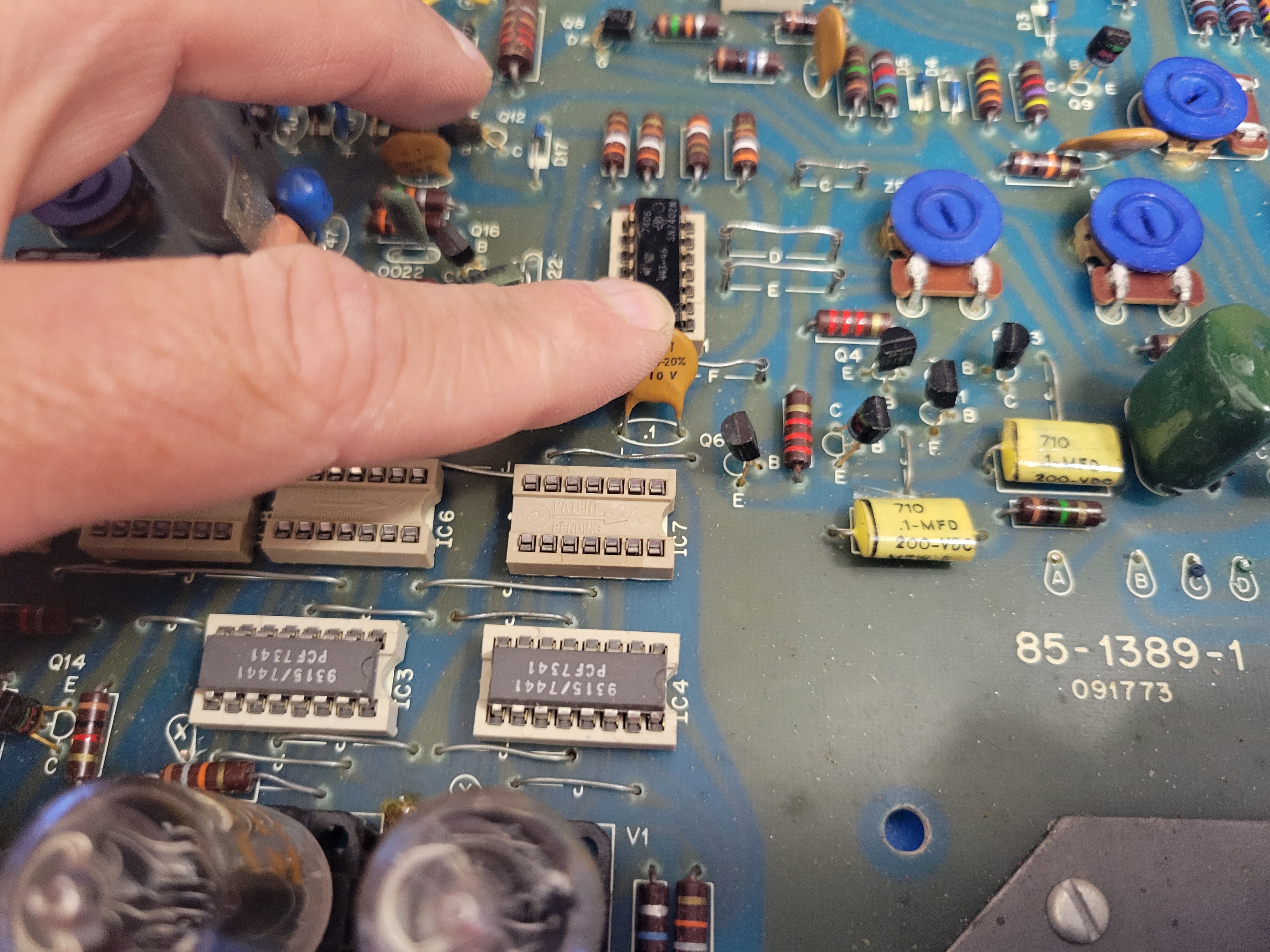
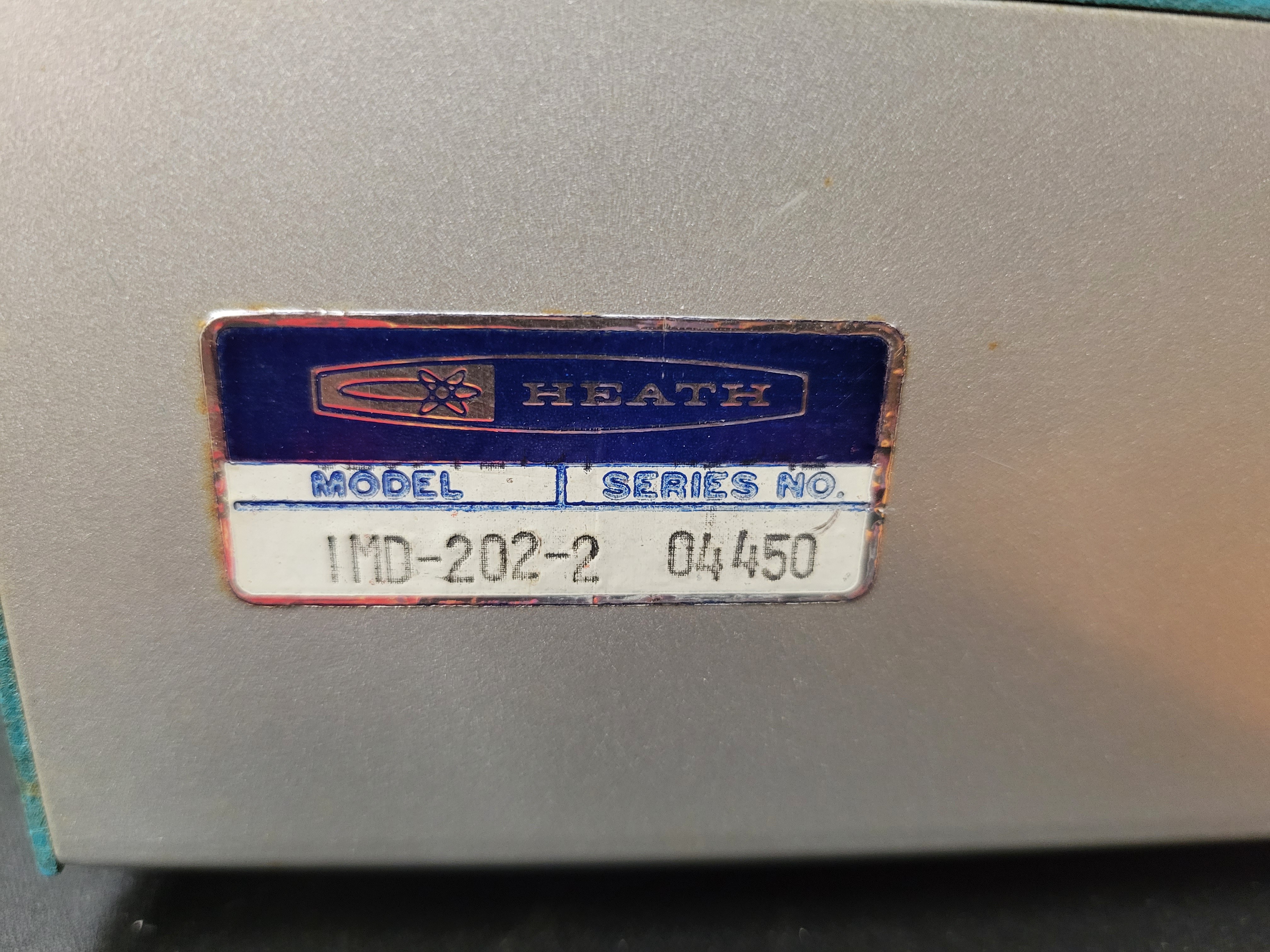
See the latest blog entries for a very detailed description of building my latest design based on the Bell & Howell IMD-202 Digital Multimeter. These blogs walk step by step through every phase of the build. The meter is the most available of the original period cases and parts that I resto-mod. They are commonly available on E-bay for a reasonable price. This design has the lowest part count and is the easiest to build.
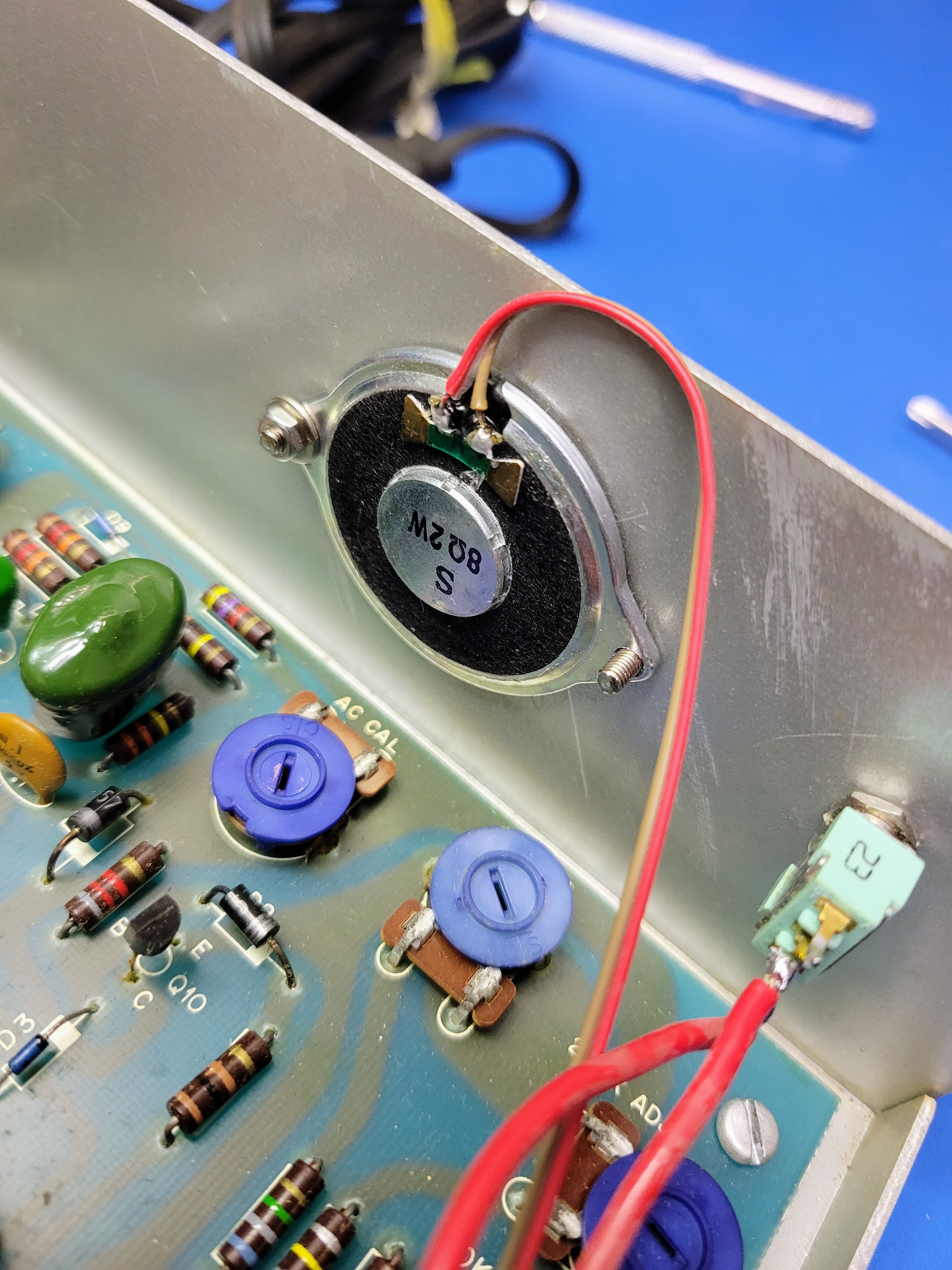
The video below demonstrates my latest designs. These utilize a couple different display technologies. One was designed and built by request for a vision impaired gamer so it has no display at all.


 Tom Dowad
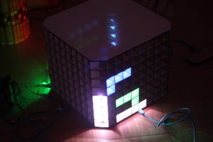
 sisam
sisam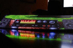
 Ian Hanschen