 John Anderson
Once you have assembled the parts, it's time to get busy building.
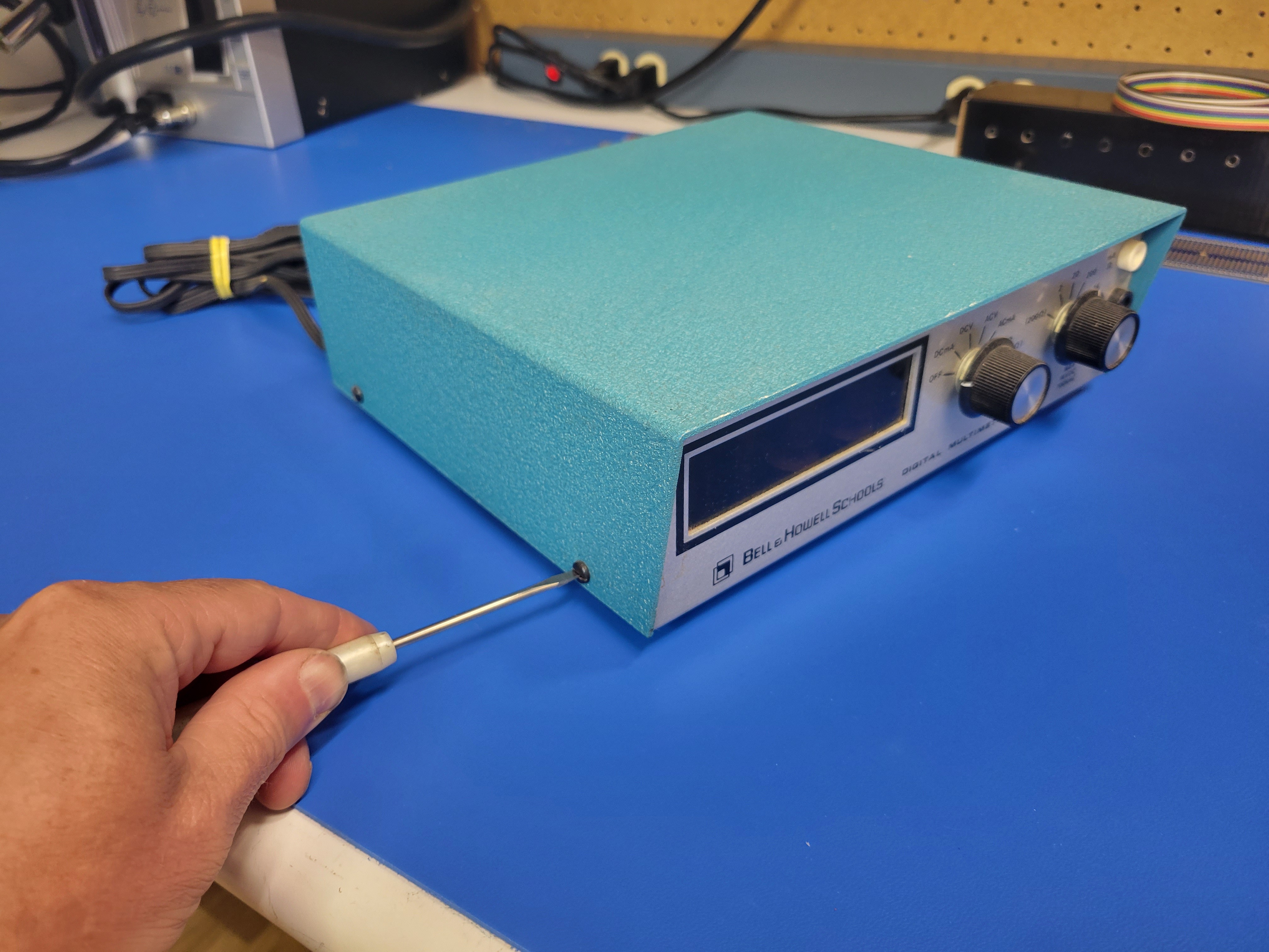
Start by removing the four screws that hold the top portion of the case to the base. There are two screws on each side of the meter.
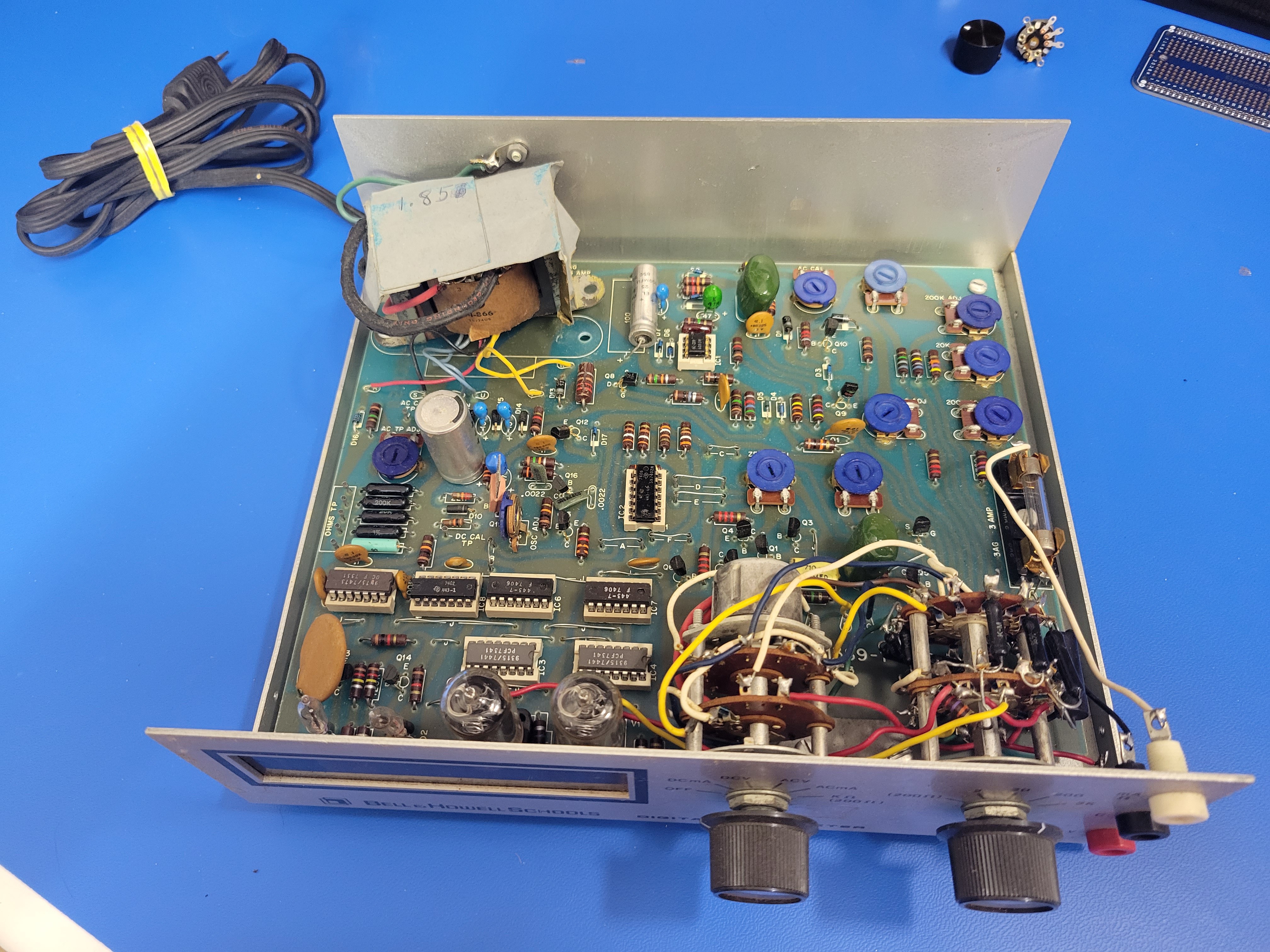
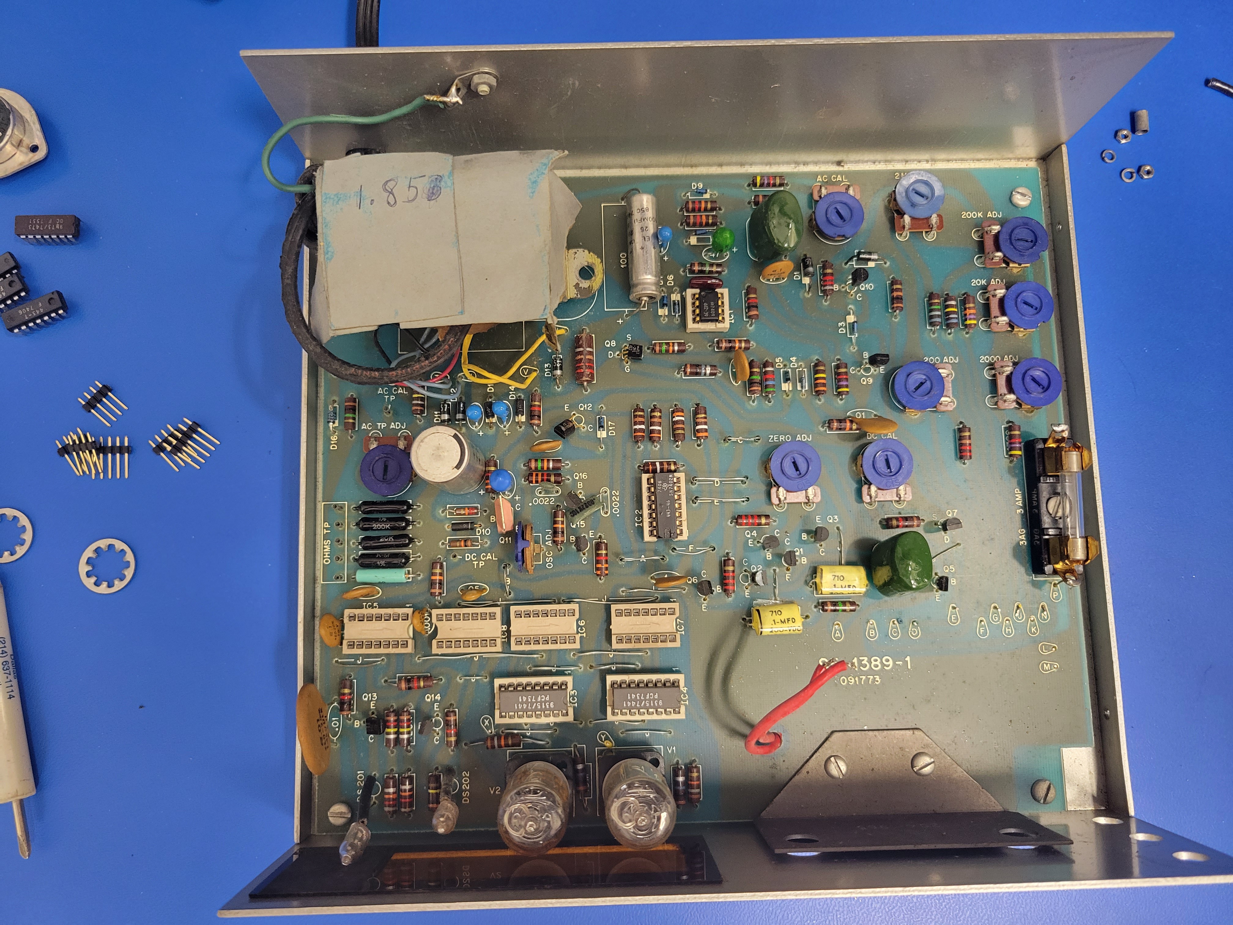
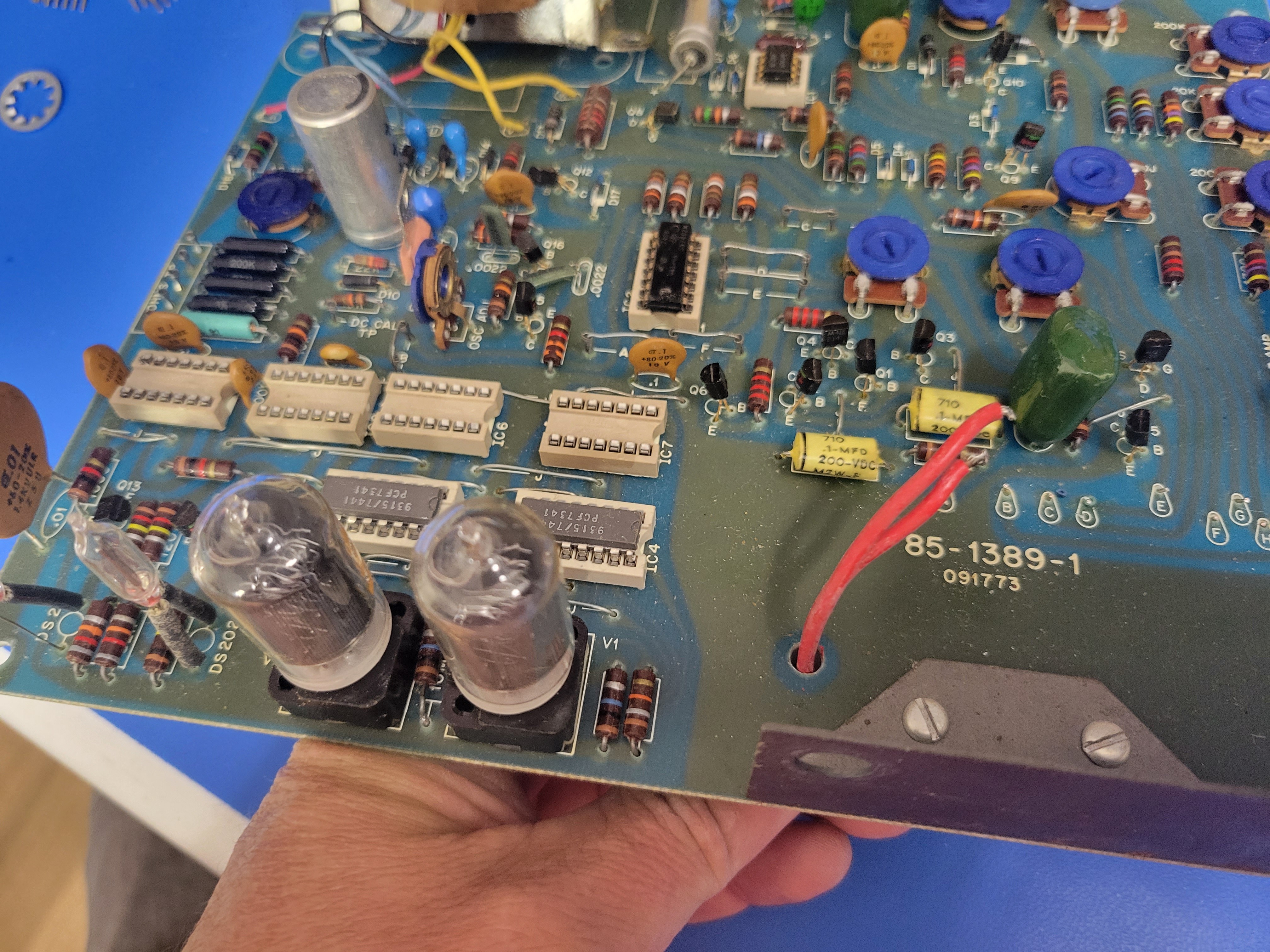
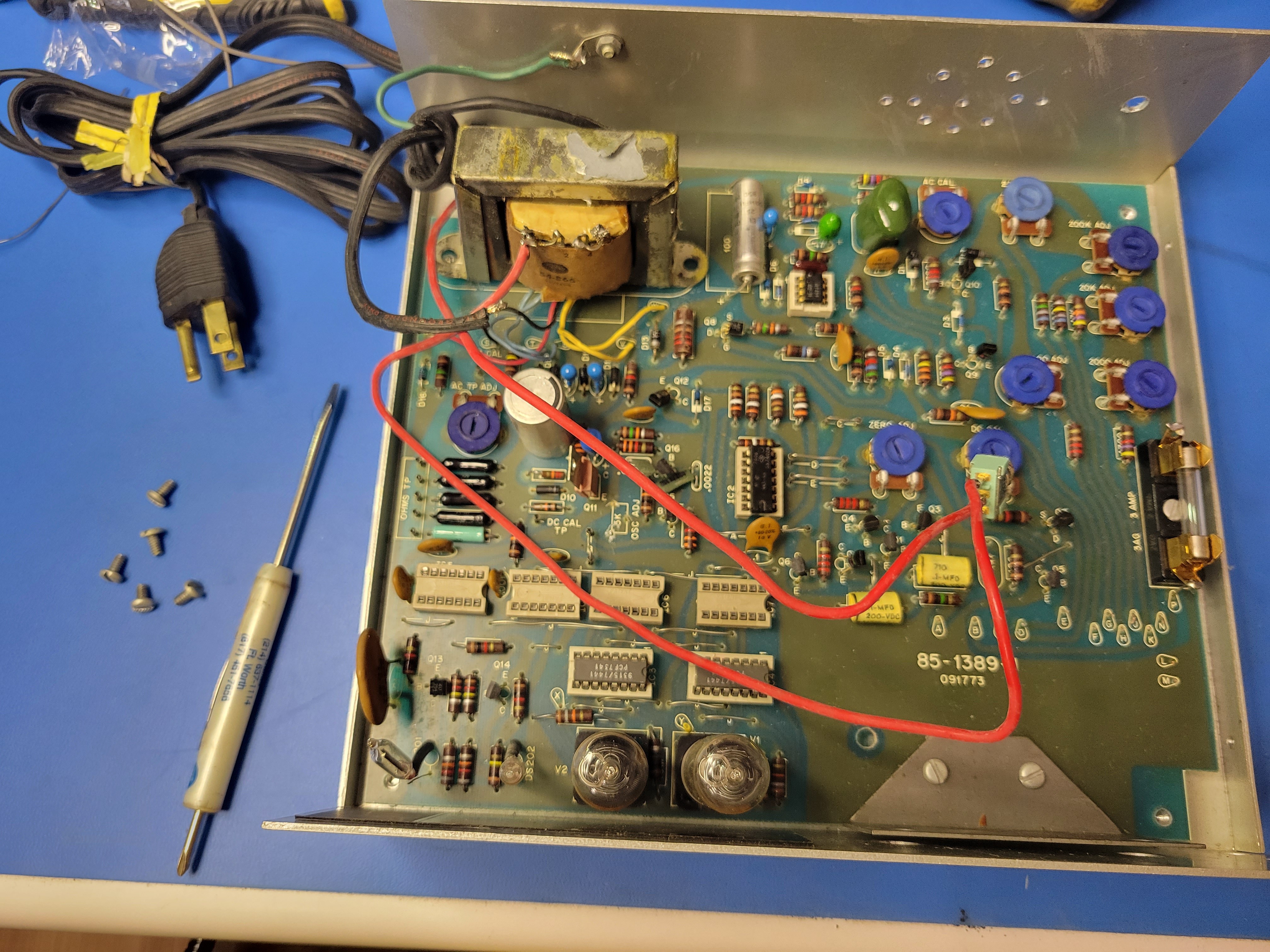
Once it's open, hopefully it looks a lot like this. Note: this unit was missing one of the screws and standoffs that secured the transformer.
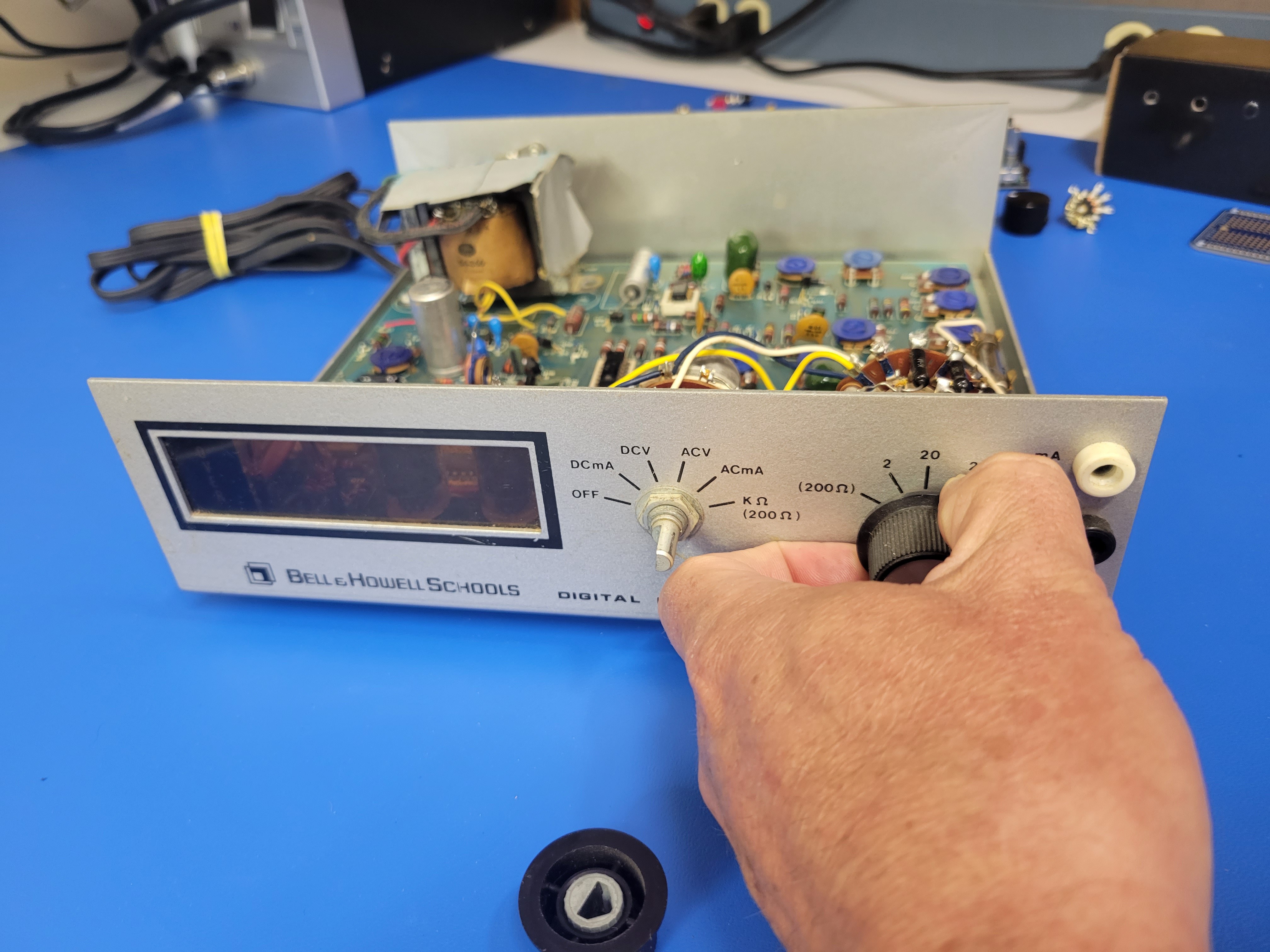
Next, you'll remove the rotary switched and banana plugs from the front. Start by pulling the knobs off.
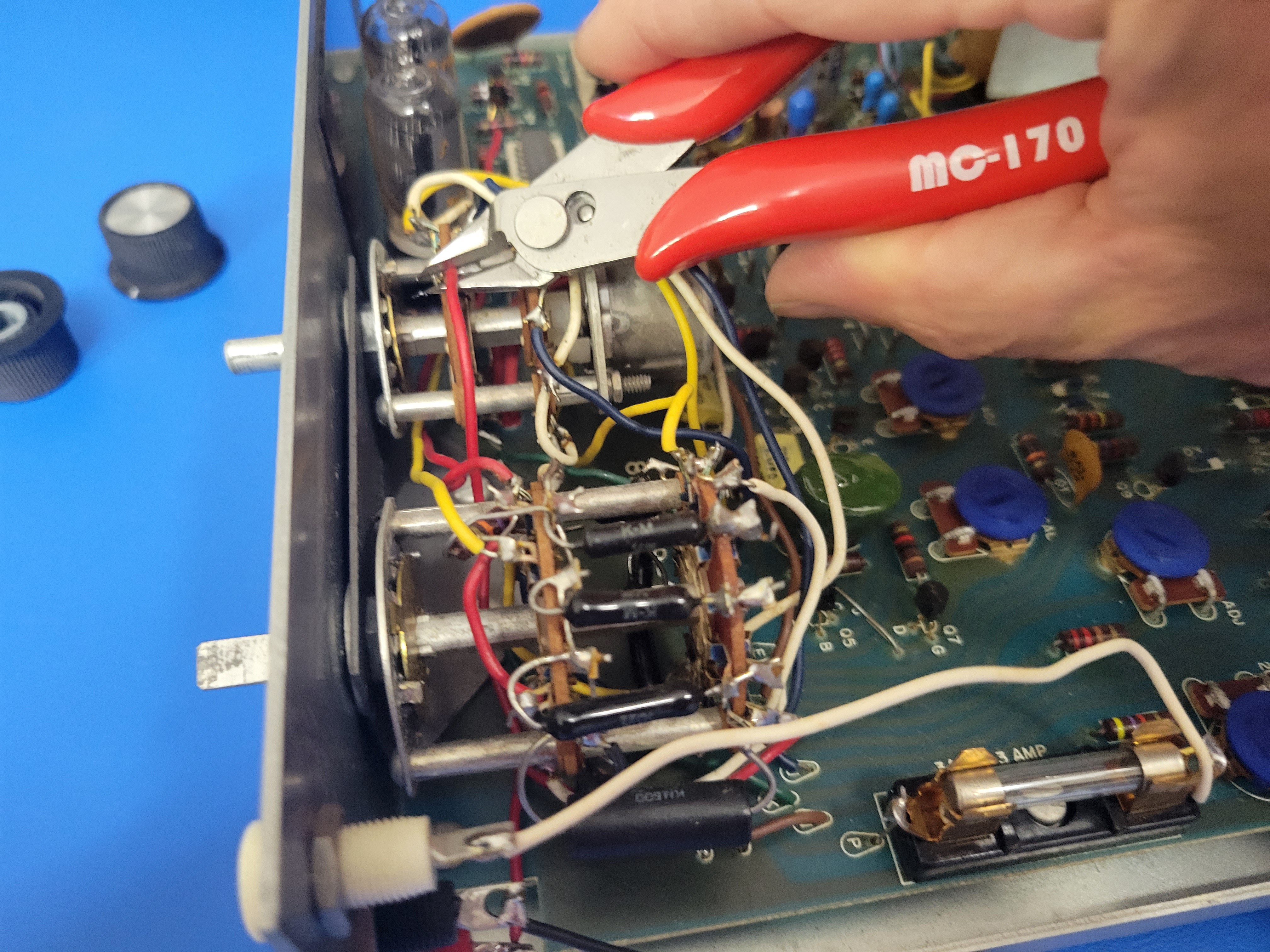
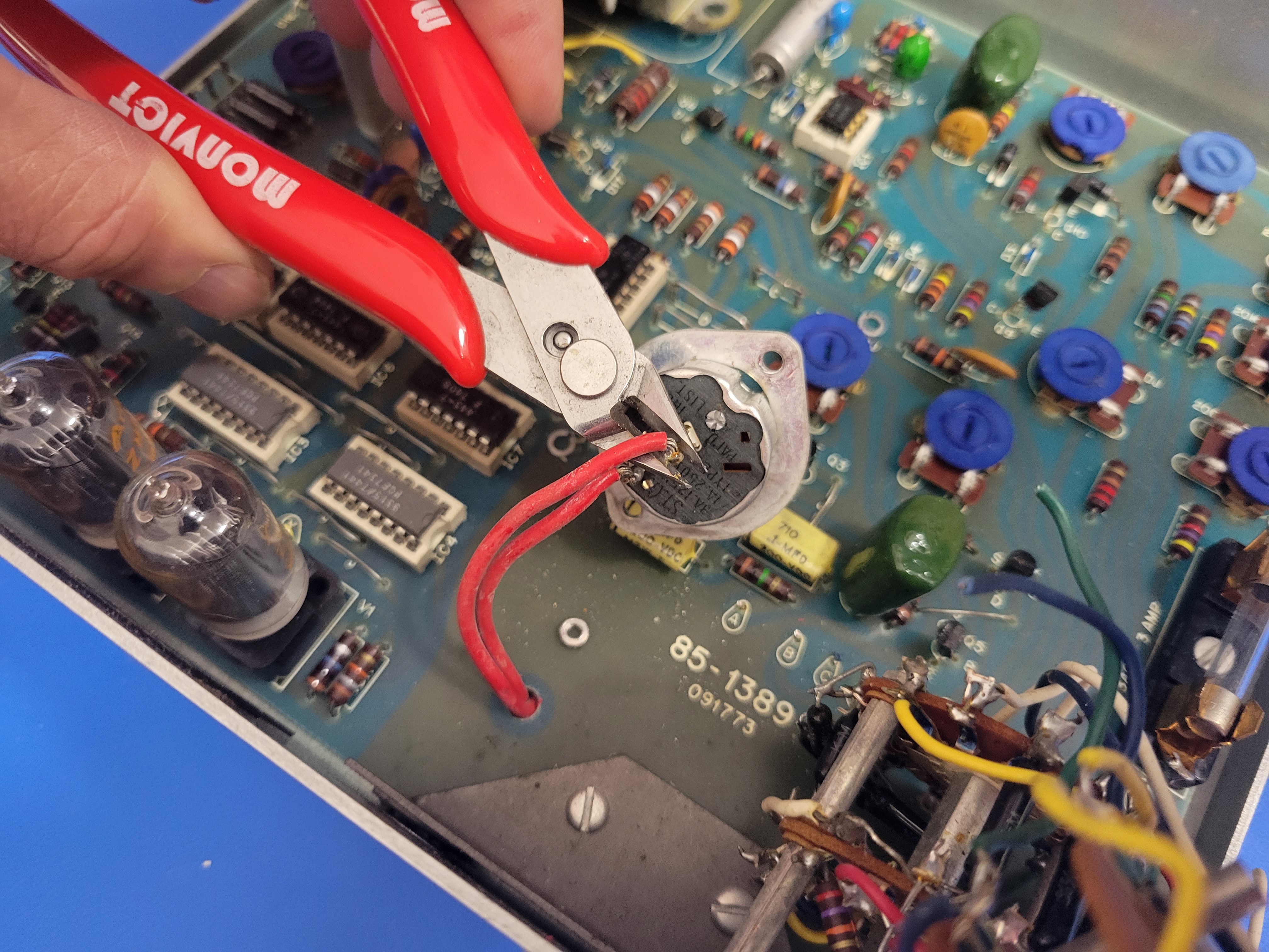
Then you'll cut the wires connecting the three banana plugs.
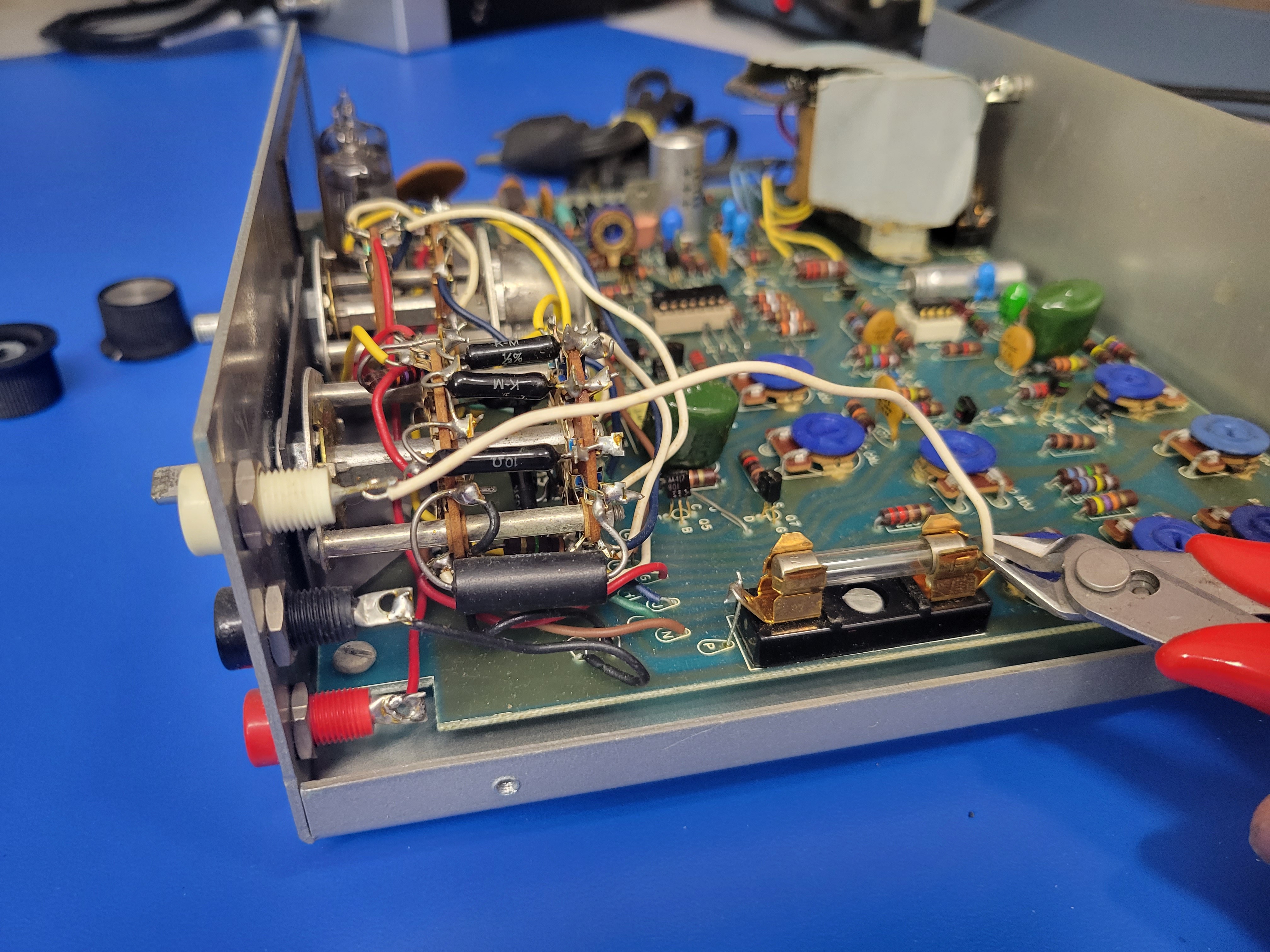
Note: the red plug is connected to the left rotary switch.
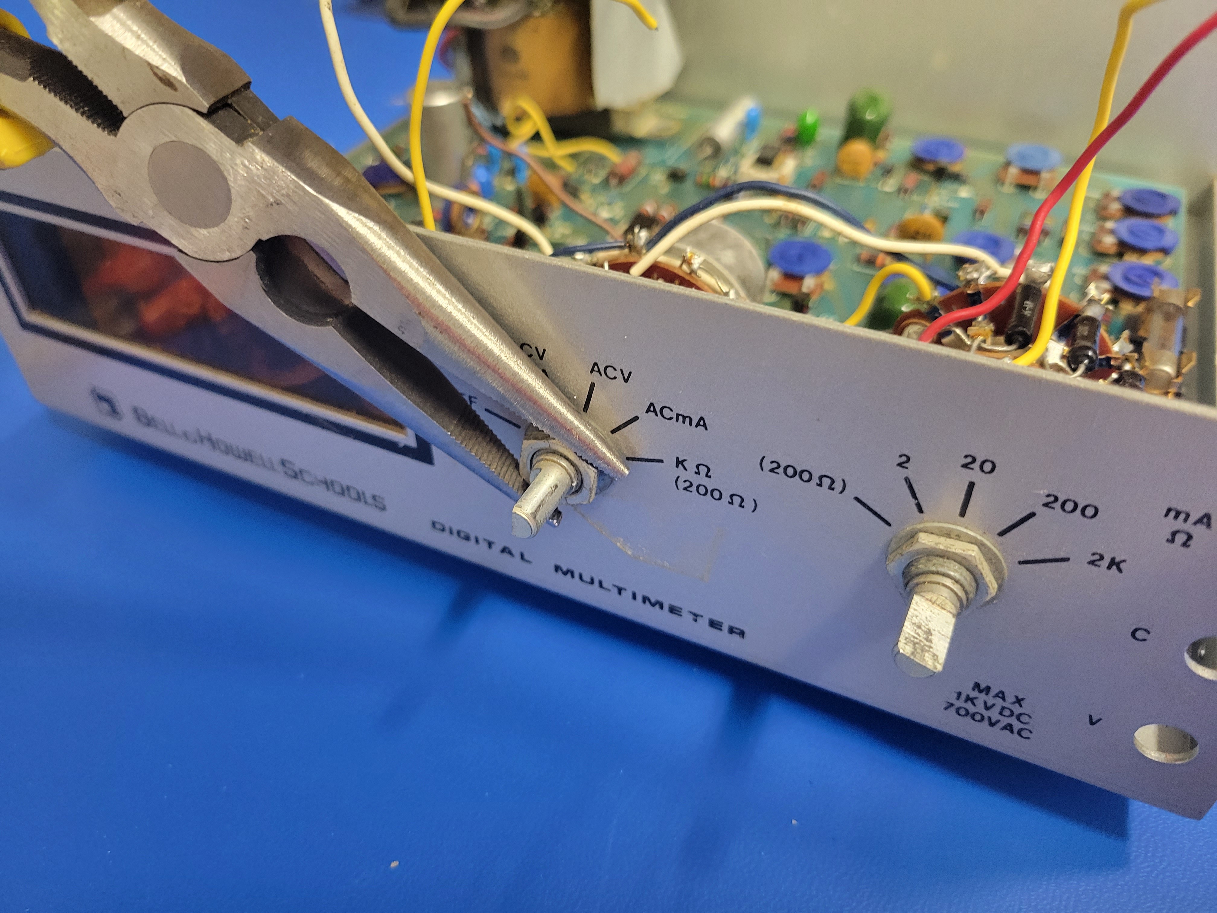
Now you can use a pair of needle nose pliers to loosen the nuts on the three plugs and remove them from the faceplate.
Next, cut the wires connecting the rotary switches to the PCB.
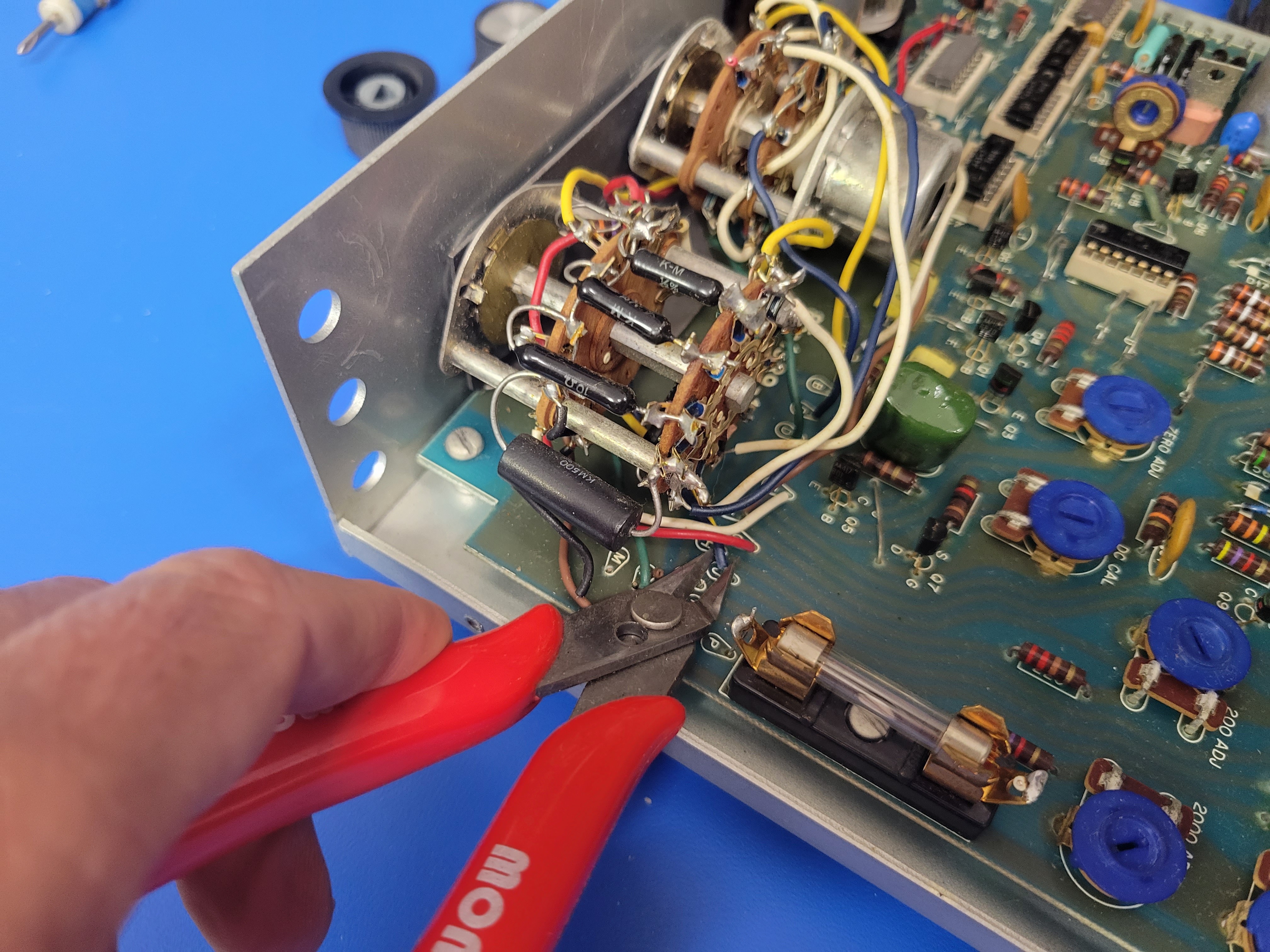
Don't forget the two wires connecting the rotary switches to the PCB just behind the nixies.
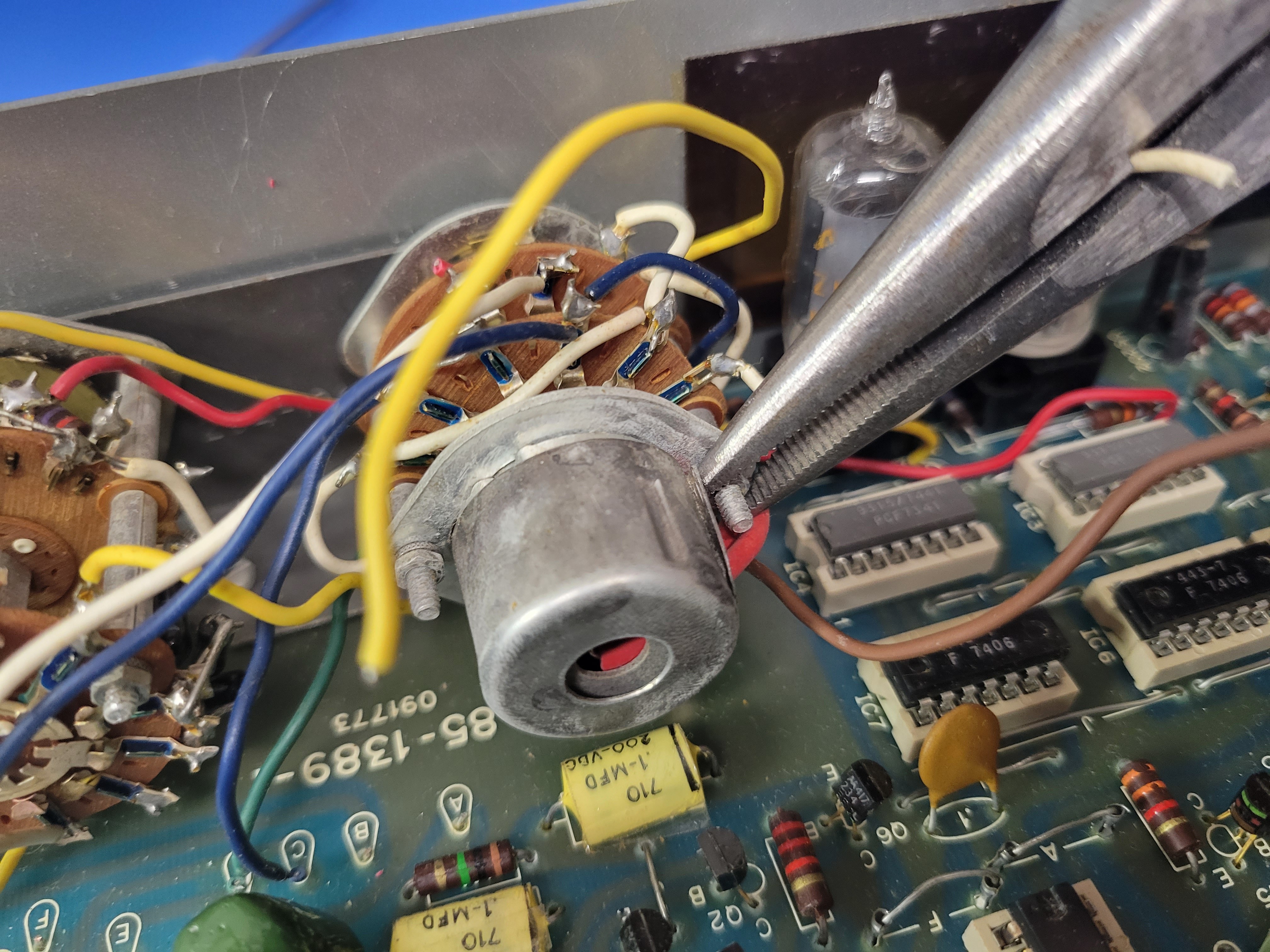
This cap will have to come off. A small flathead screw driver will work (ignore the needle nose pliers).
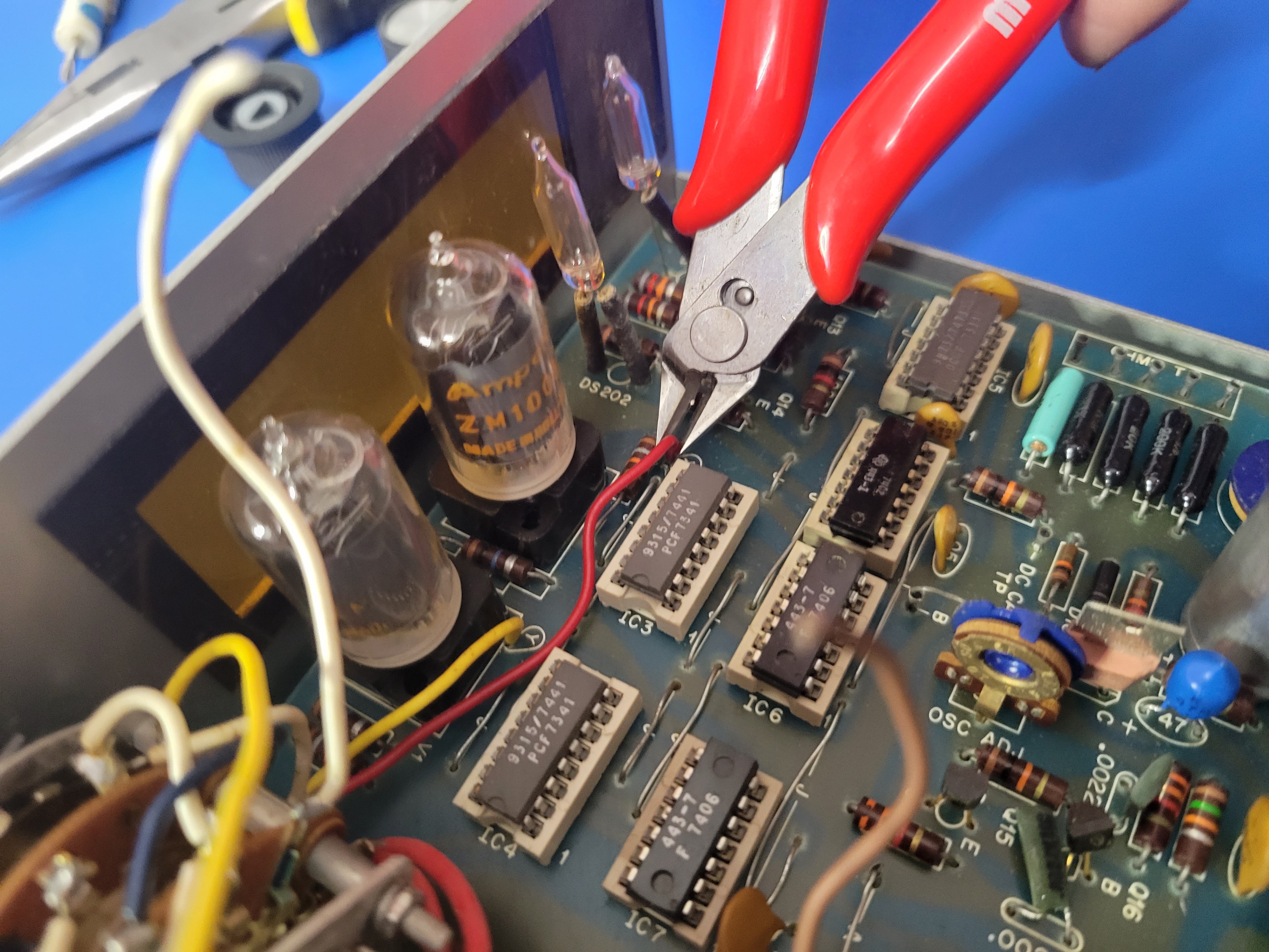
Once the cap is off, you can clip the two red wire off. You'll want to keep these wire as long as possible. In the pic below, I removed the on/off switch from the rotary switch before doing this. That is not required.
Now you can remove the rotary switches from the faceplate.
Then remove IC5, IC6, IC7, and IC8 from their sockets on the PCB.
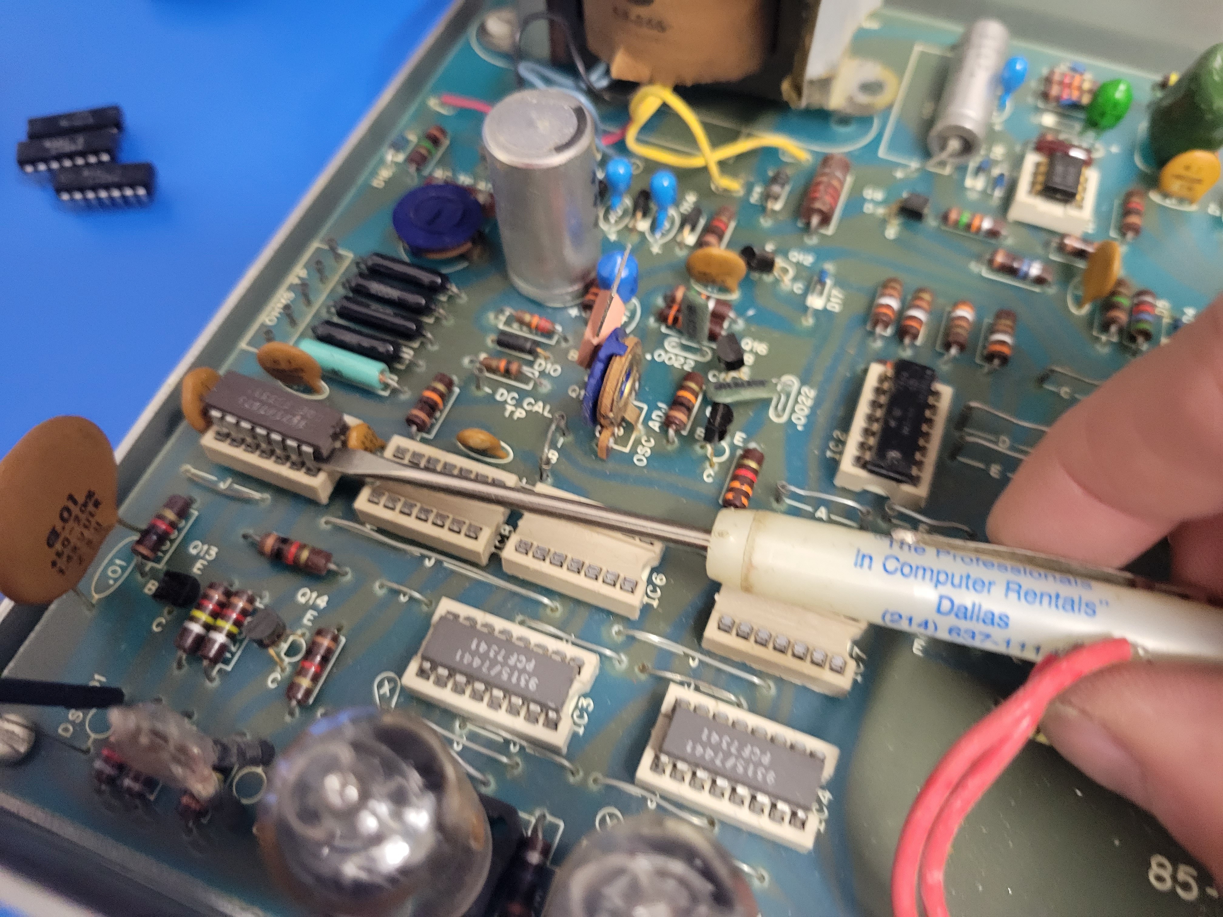
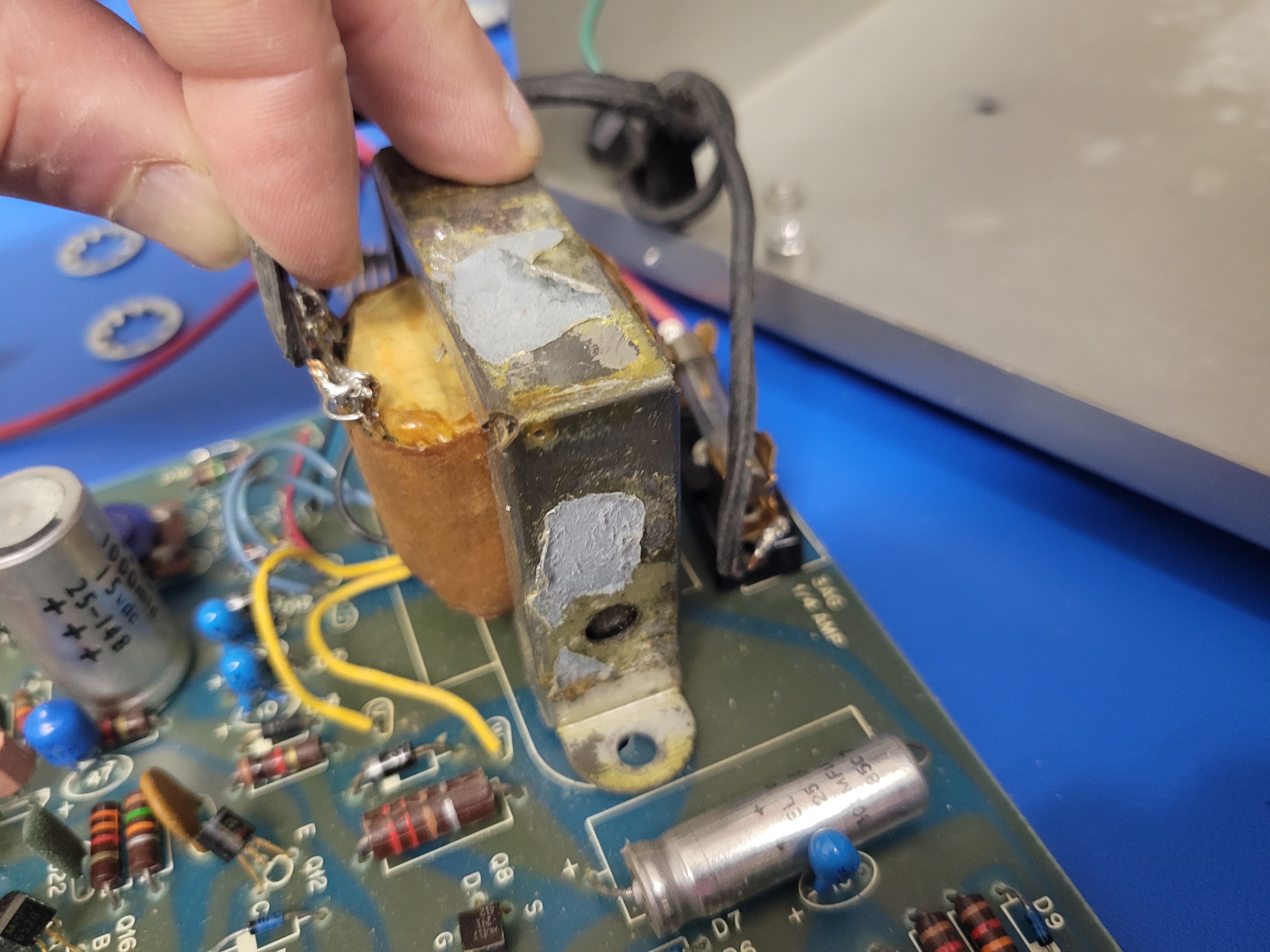
Now it's time to remove the PCB from the base of the case. Remove the 5 screws holding the PVB to the standoffs mounted to the case. Three are on the front left, front right, and rear right corners. The other two hold down the transformer.
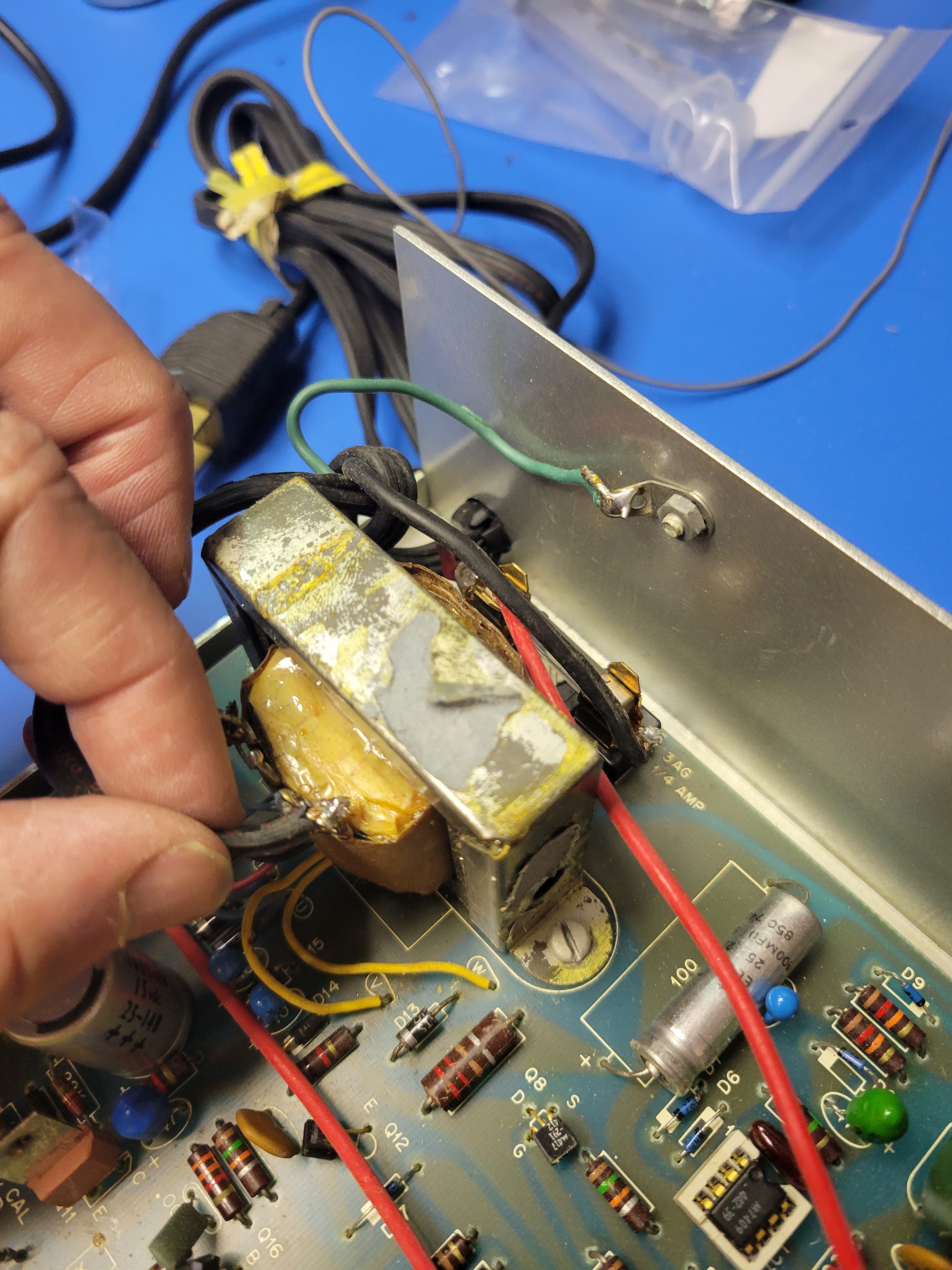
Once the board is free, pull the to red power wires through the board and lift it up. You will use these red wires to turn the device on and off. So leave them intact and soldered to the boars. The PCB will still be connected to the power cord in the rear at the transformer and fuse. You will need to clip these connections to the power cord at the soldered connections.
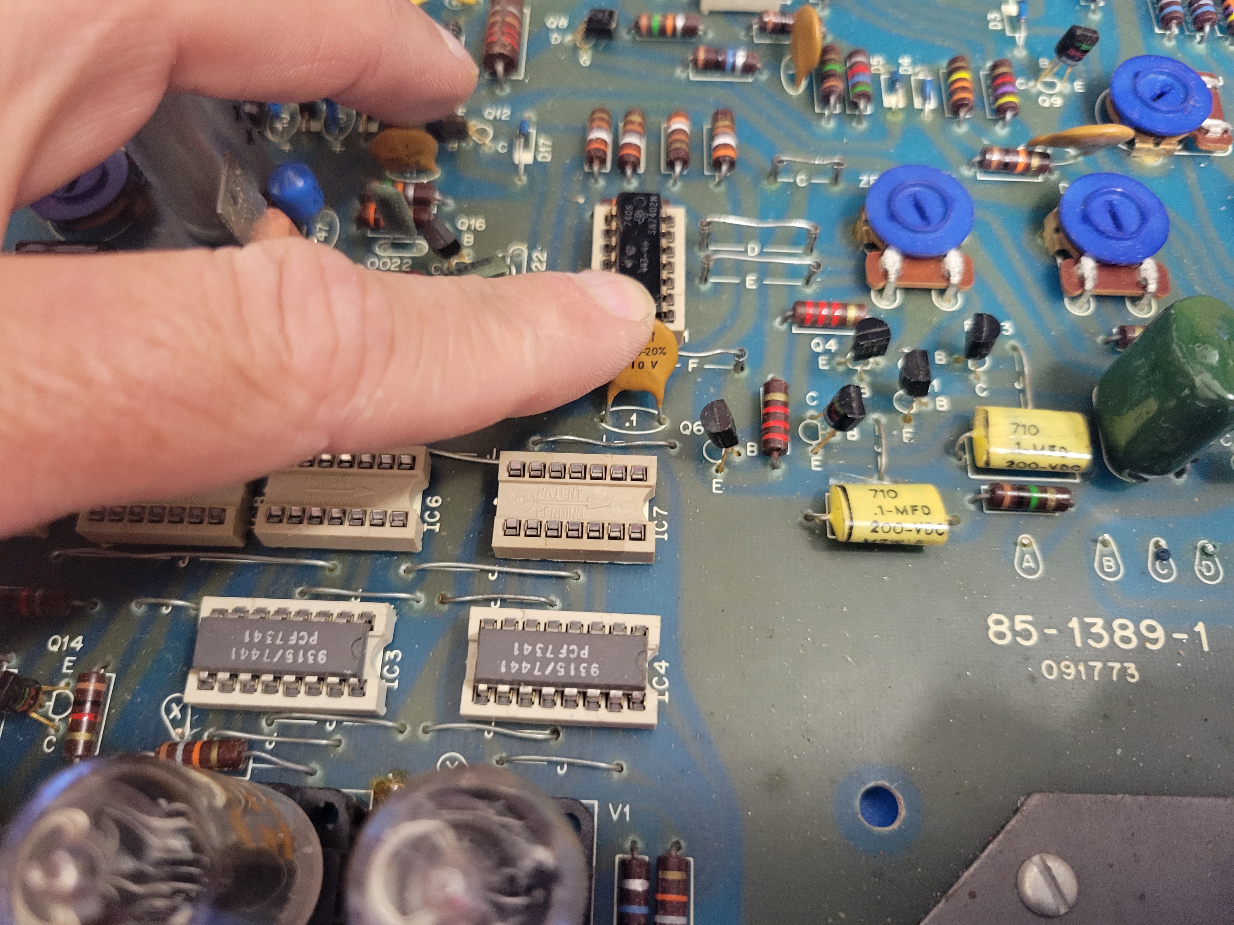
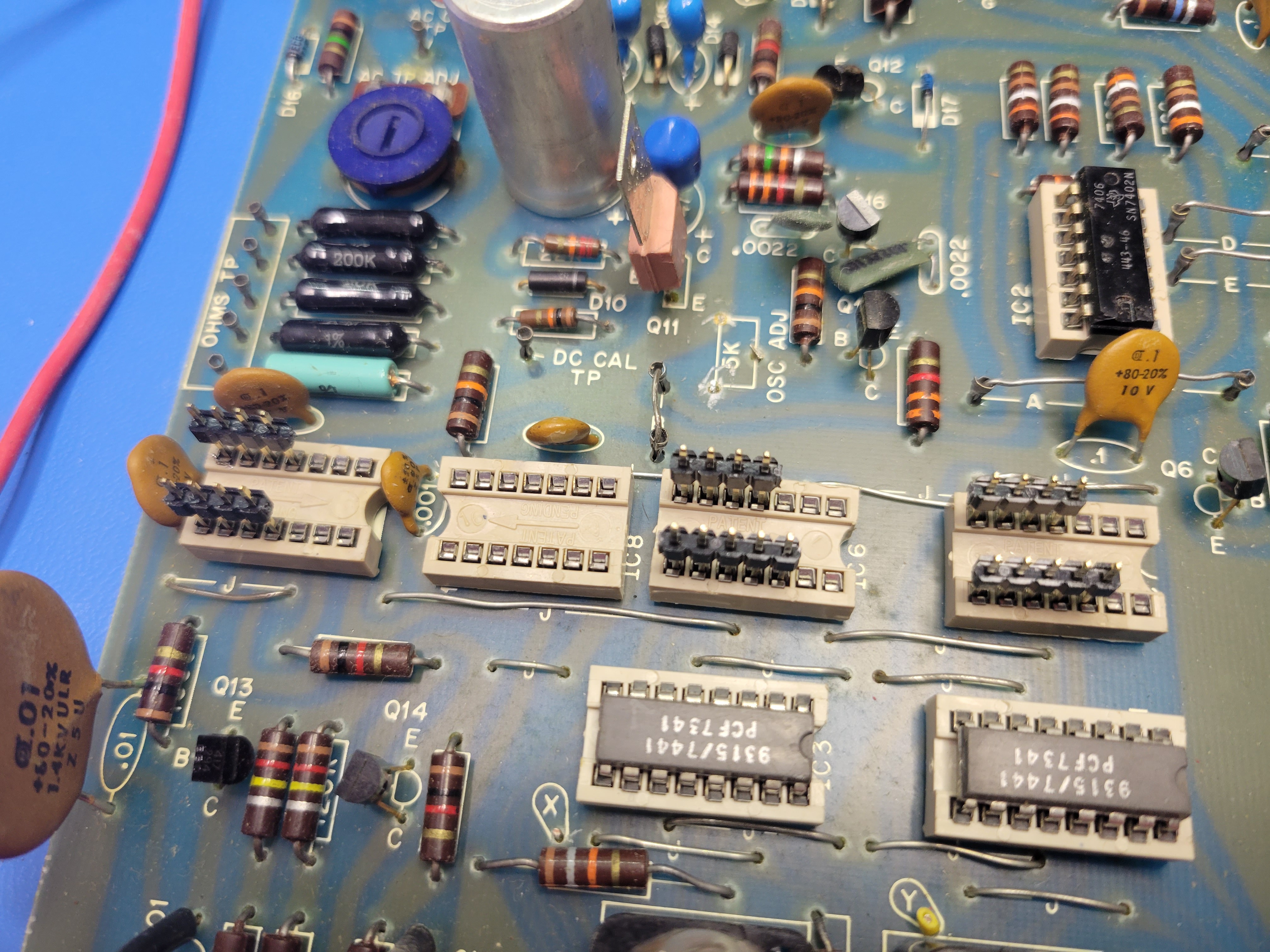
Next you'll make some room for the controller board. Start by pushing this cap behind IC7 down and out of the way for the controller board.
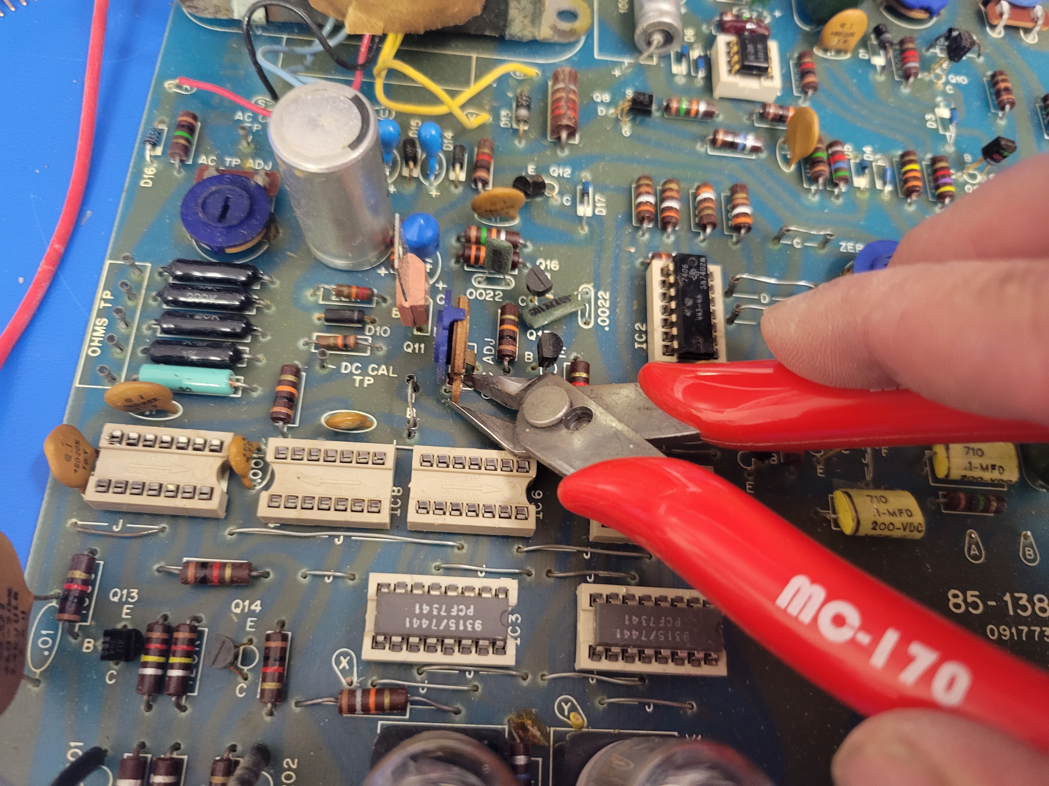
Then clip and remove the pot behind IC6.
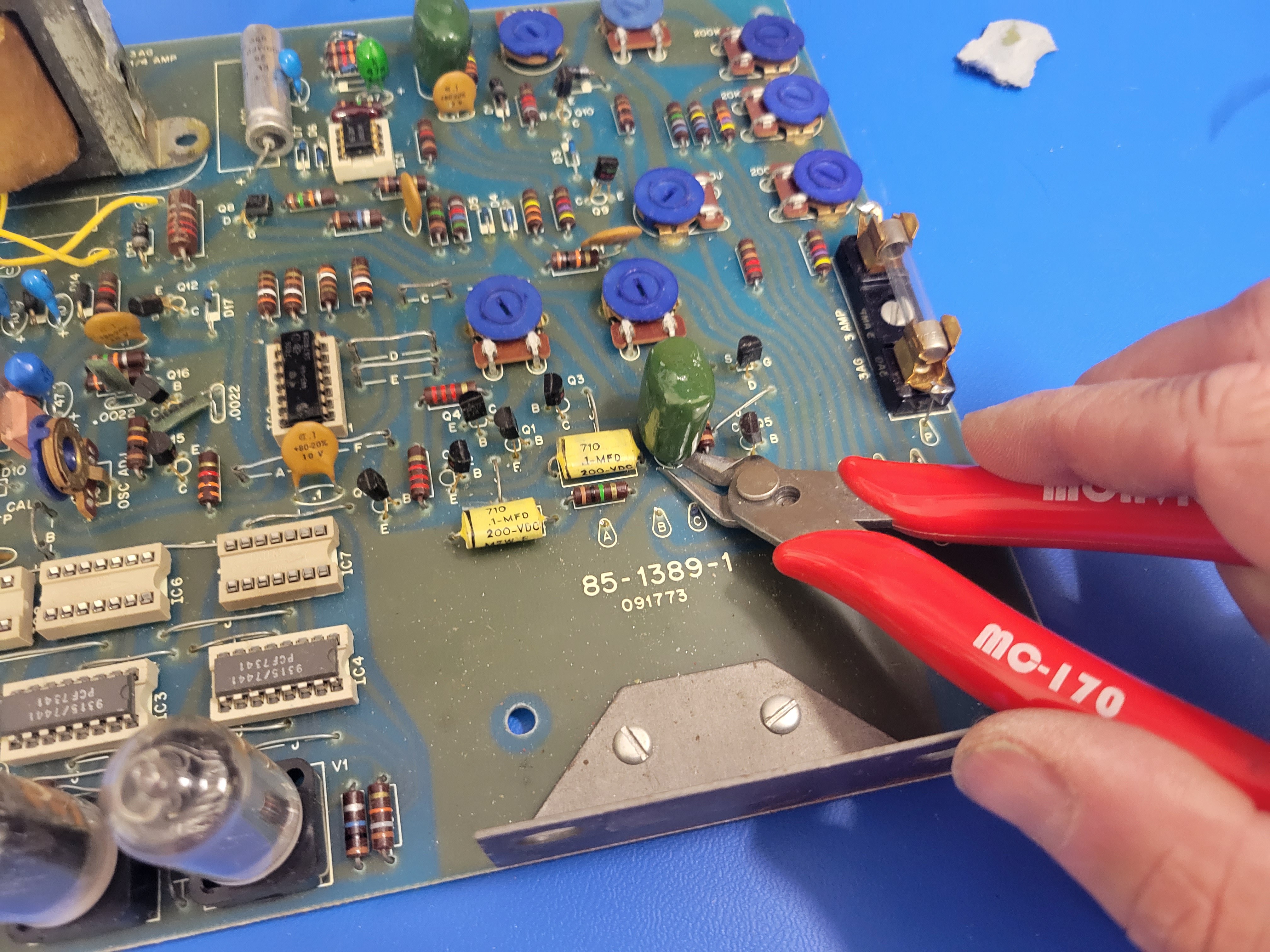
And clip/remove the large green capacitor behind the rotary switches (at least where the rotary switches were).
The final step of making room for the controller board is grinding/filing a little off the edge of the controller board so it will clear the large ceramic on the far left side of the board. Be careful not to file or grind into the wire trace that connects the power busses.
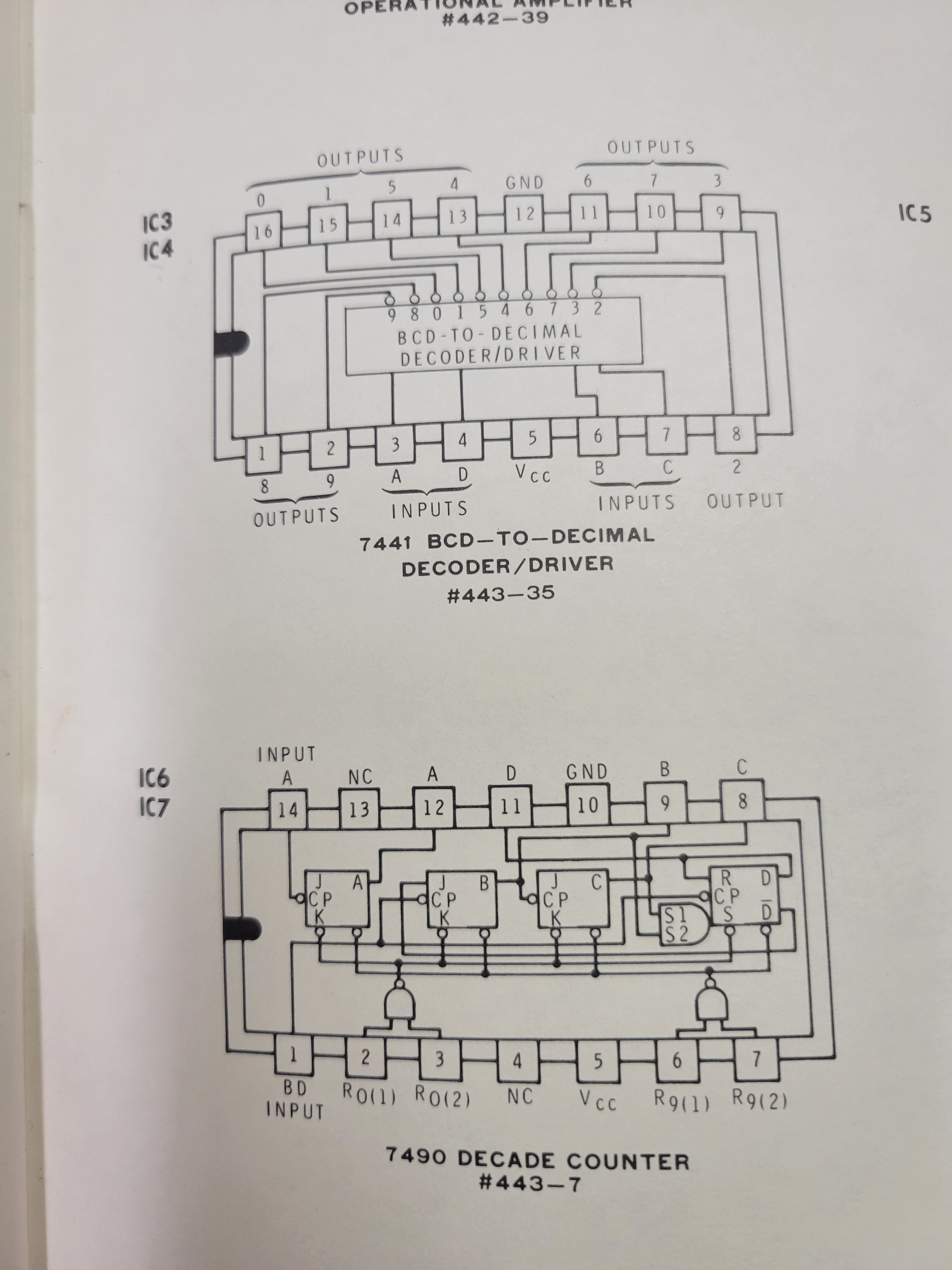
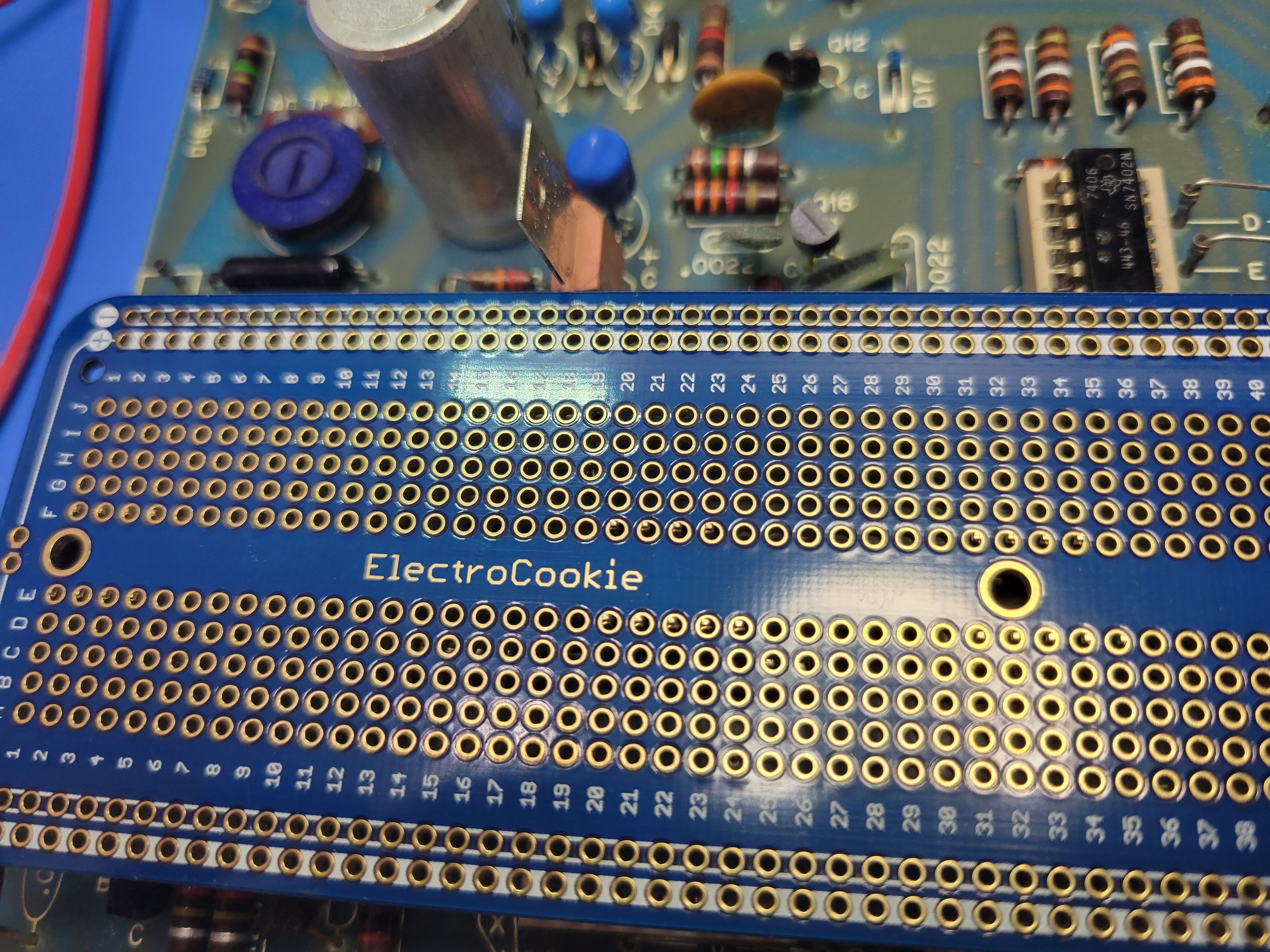
Now it's time to install some headers and fit the controller board in place on the PCB. The controller board will need to be connected to the sockets for IC5, IC6, and IC7. IC6 and IC7 are 7490 decade counters that controlled the digits displayed on the nixies. So, they provide the 4 pin interface to select the digit displayed on the corresponding nixie. They also provide the 5v and ground needed to power the controller board. IC5 will provide the interface to the one hundreds digit and the overflow indicator.
Cut and insert 2.54 mm single row headers into the sockets for IC5, IC6, and IC7 as shown in the picture. Note: these headers are longer on one side (6 mm vs 3 mm). Insert the long side into the socket.
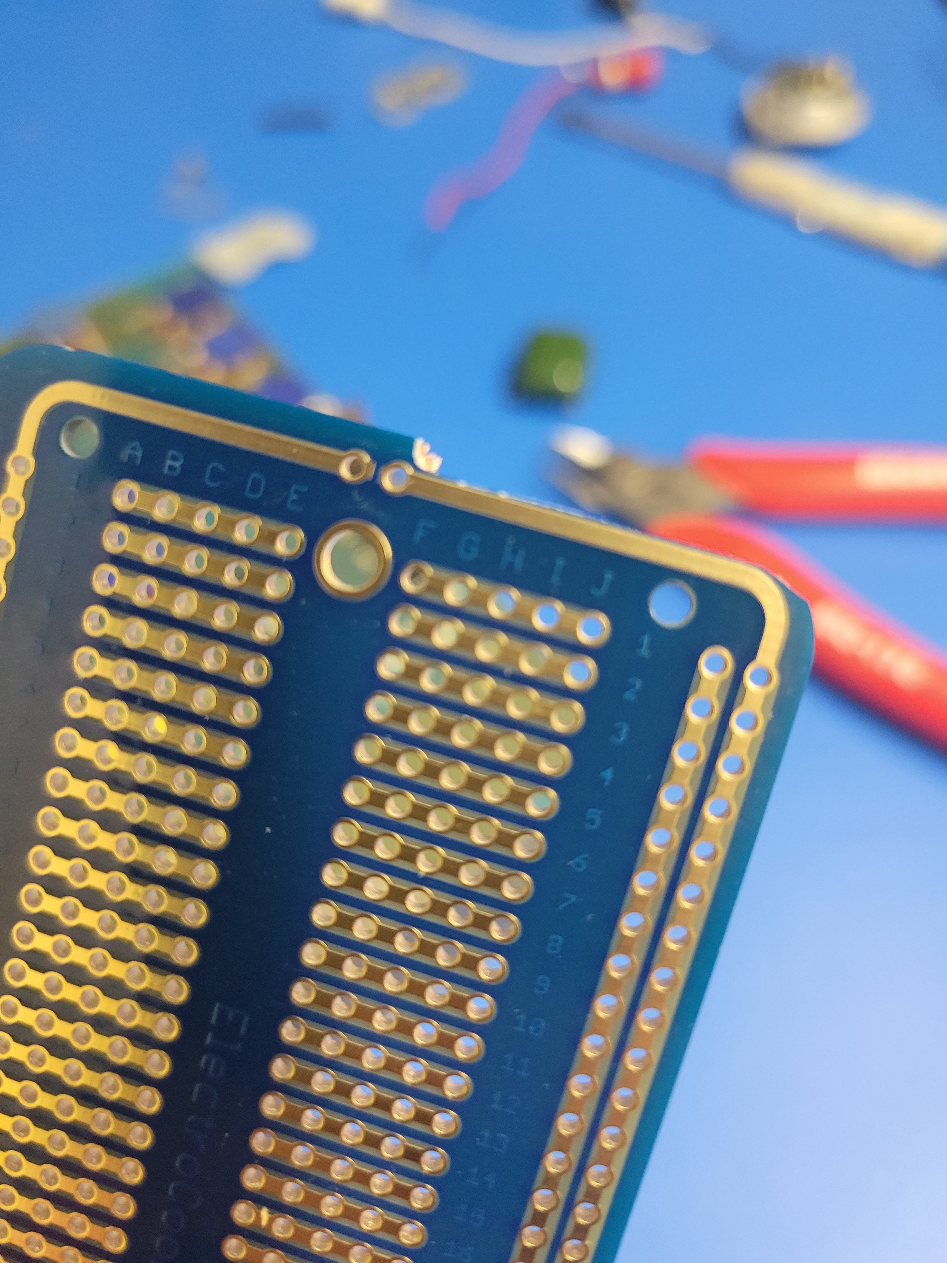
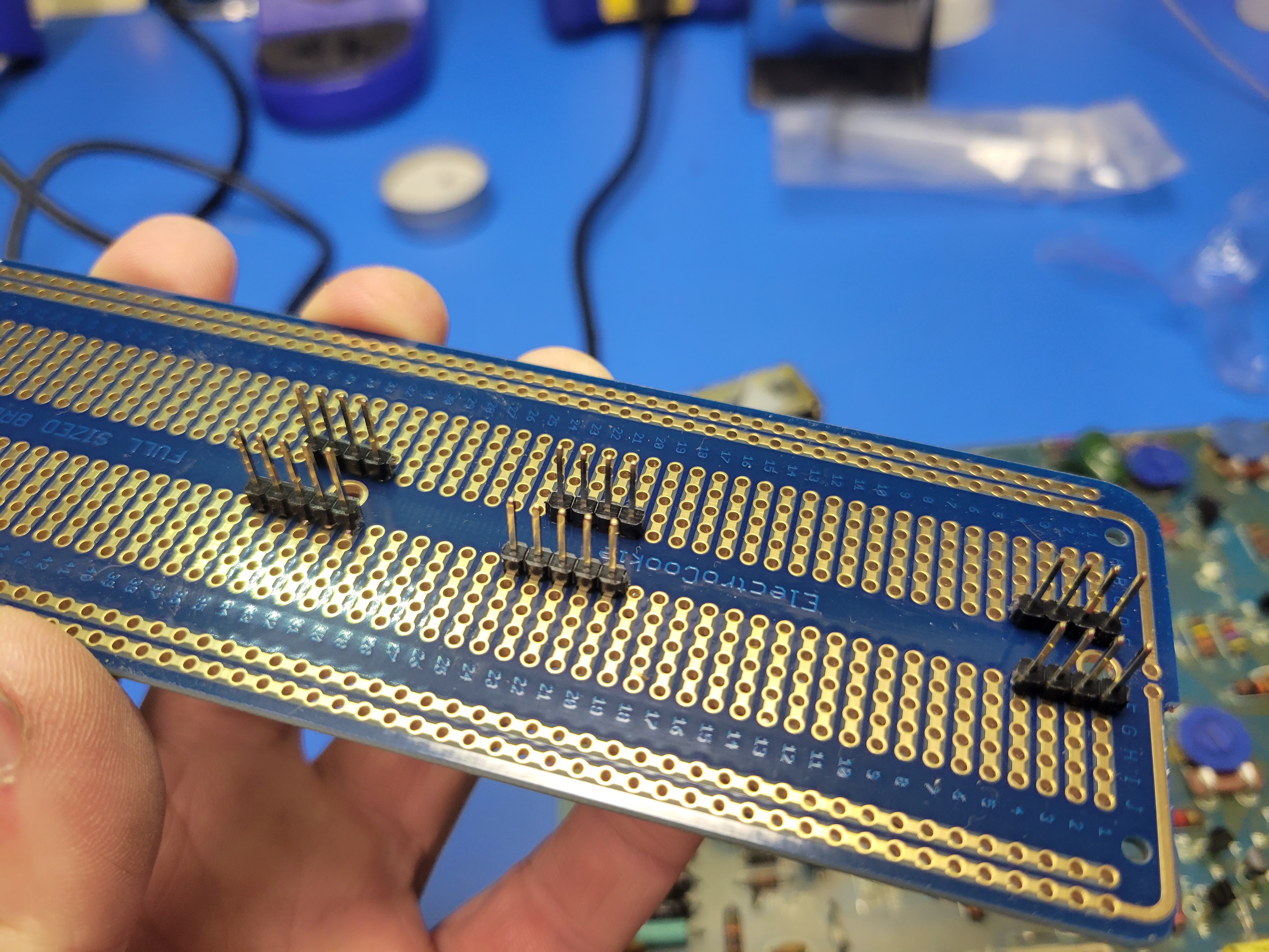
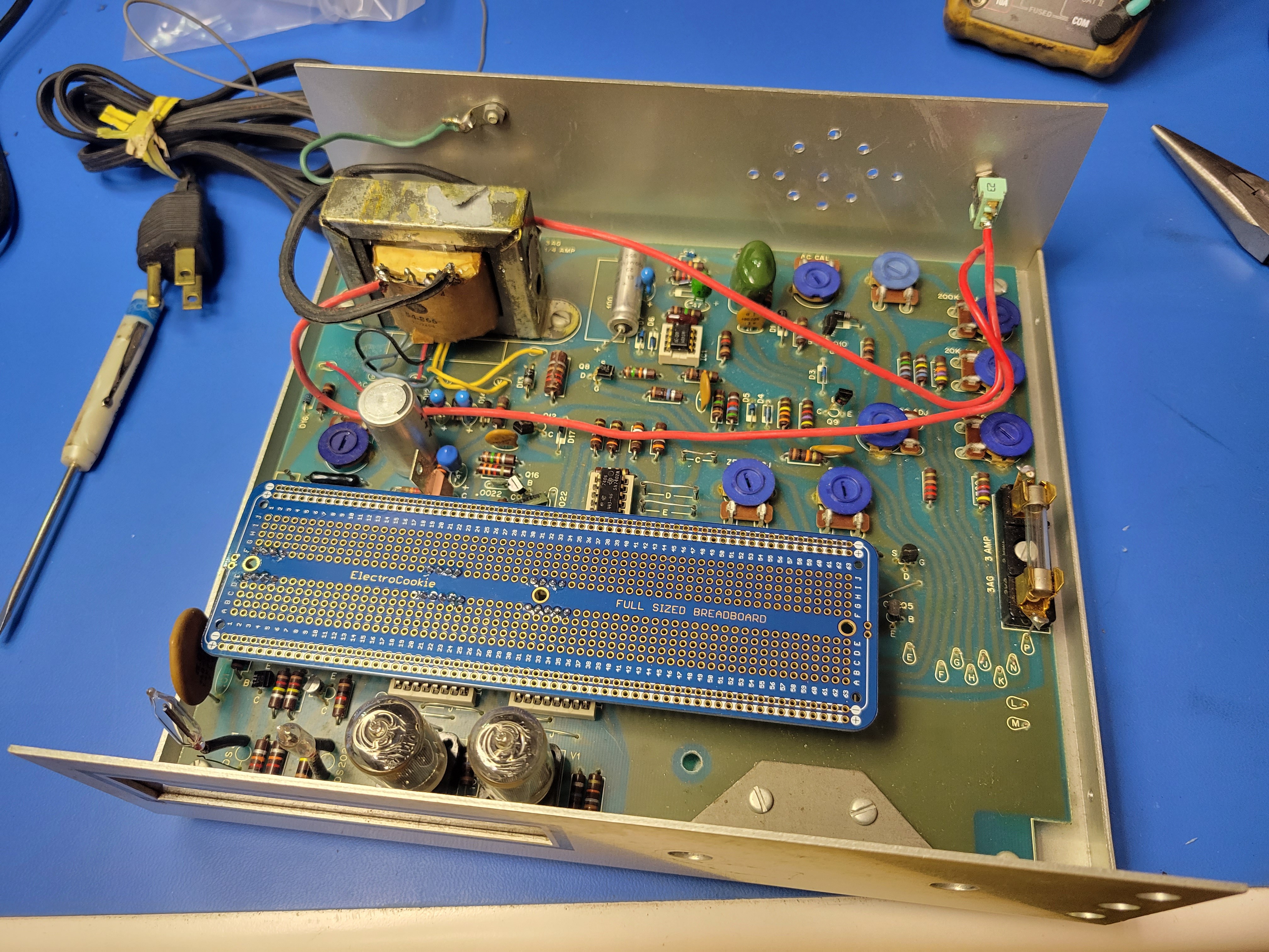
This is the hardest part of the build. You will have to line up the headers so they fit into the breadboard with the left most pins fitting into row 1 of the board. It should look like this once you get it lined up and in place. Look closely, you can see the pins poking through.
Now with the breadboard still in place on the headers plugged into the sockets on the PCD, solder the headers to the breadboard. It should look like this when you are done.
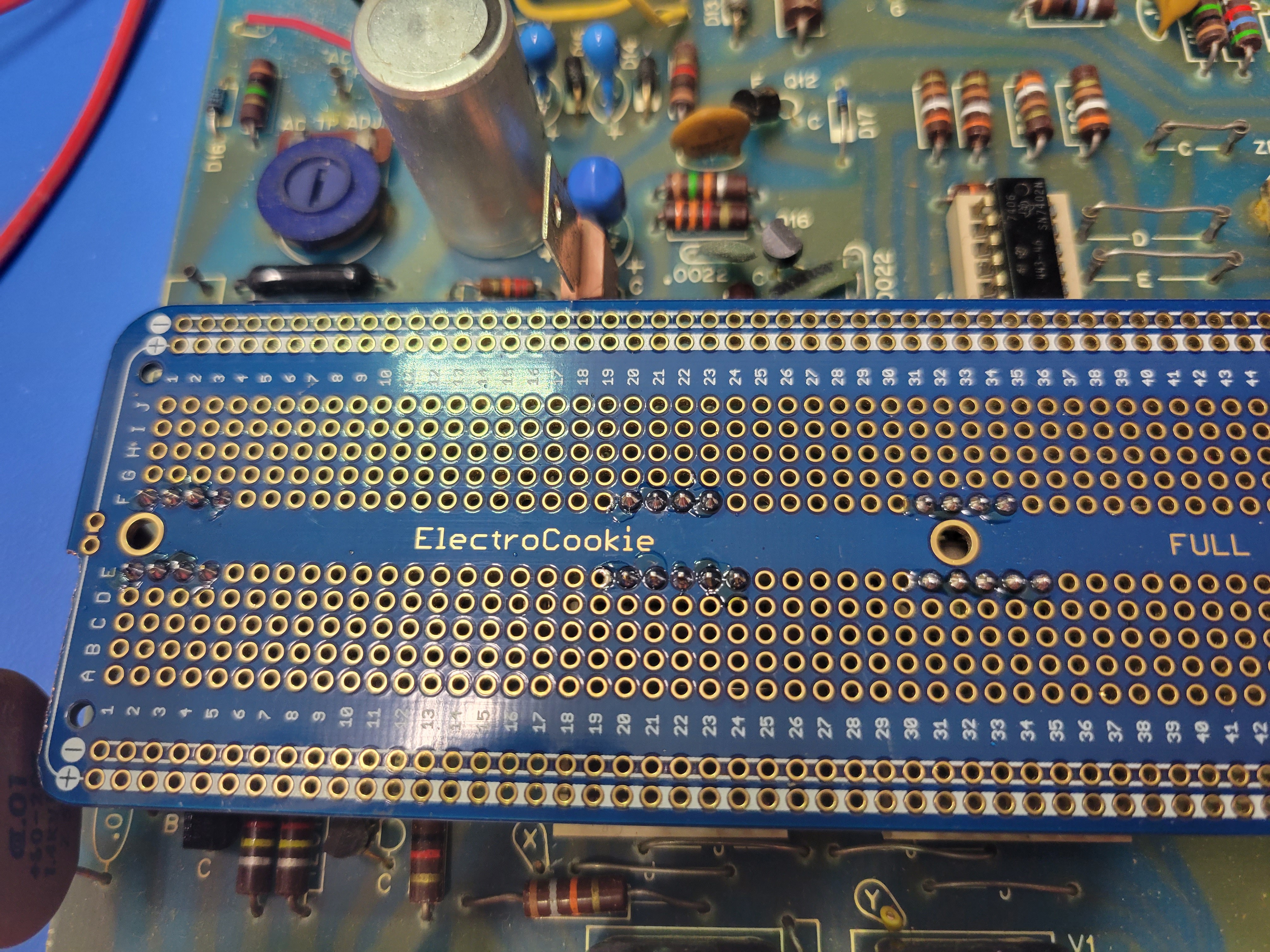
When you pull the breadboard out and flip it over it should look like this.
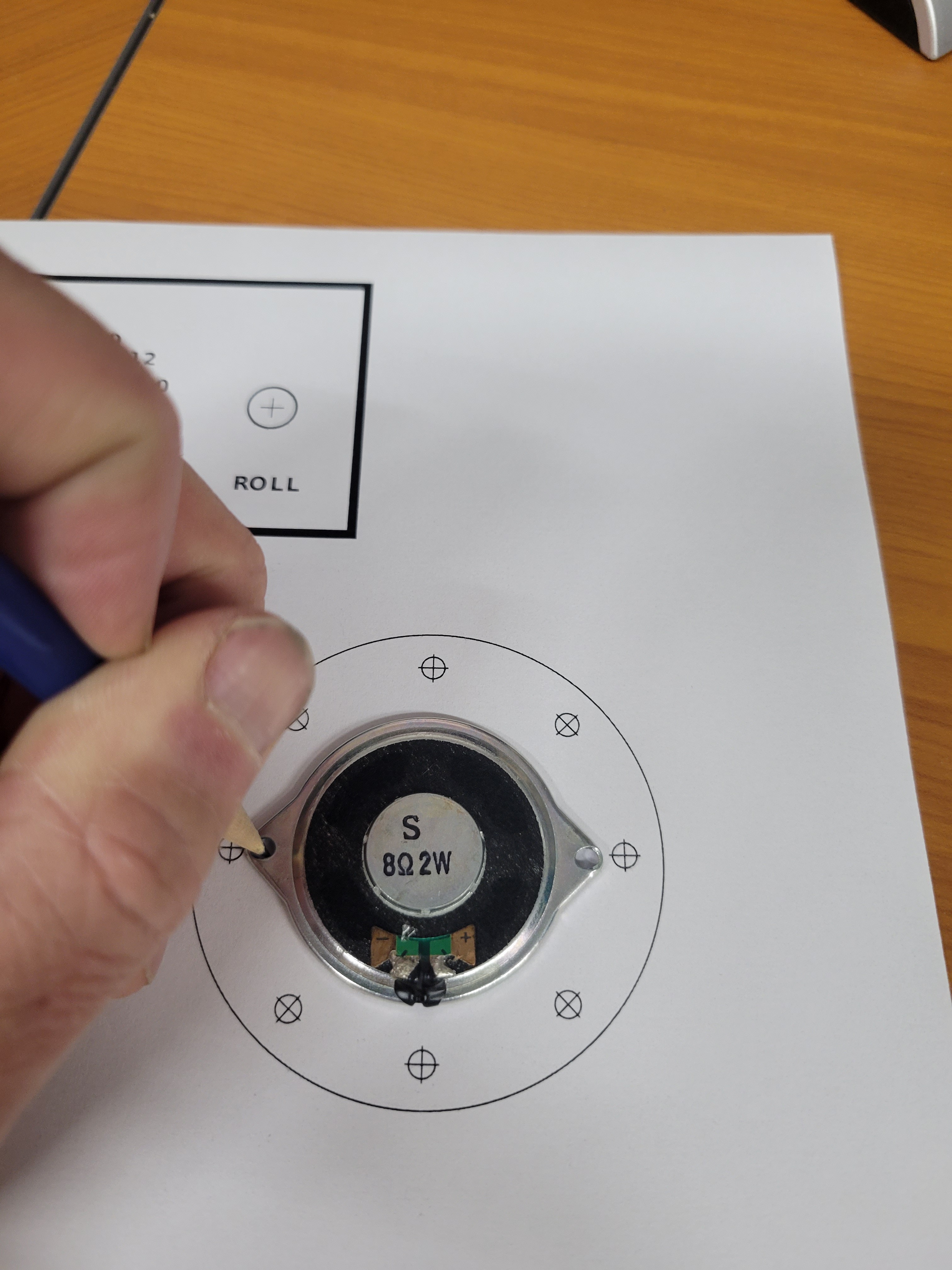
Next you'll modify the base of the case to mount a speaker and a toggle on/off switch. I suggest installing these in the rear for the case.
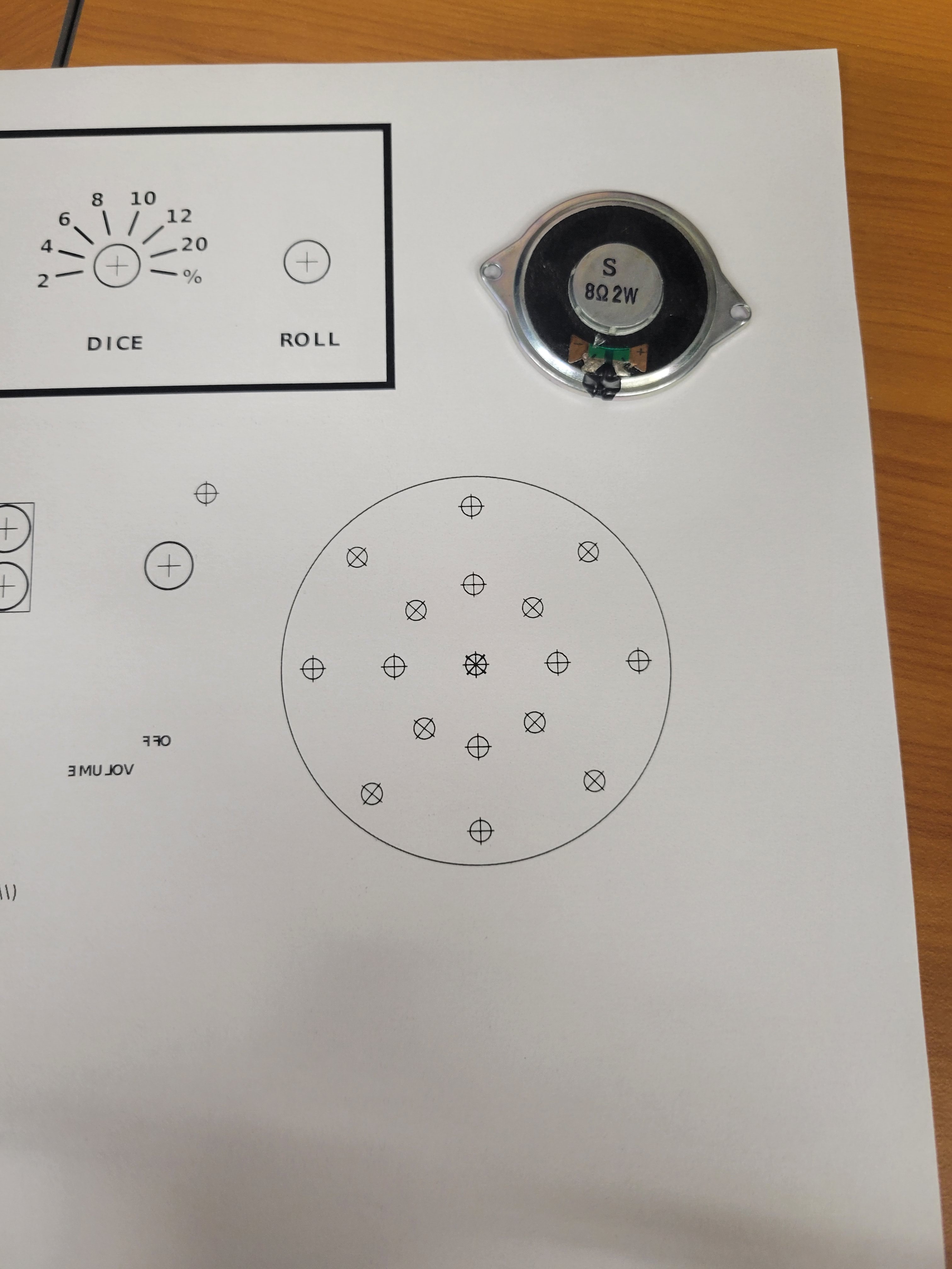
Start by creating a template for the speaker holes the allow the sound out and the holes to mount the speaker. Then print this template, cut it out, and tape it to the rear faceplate of the case.
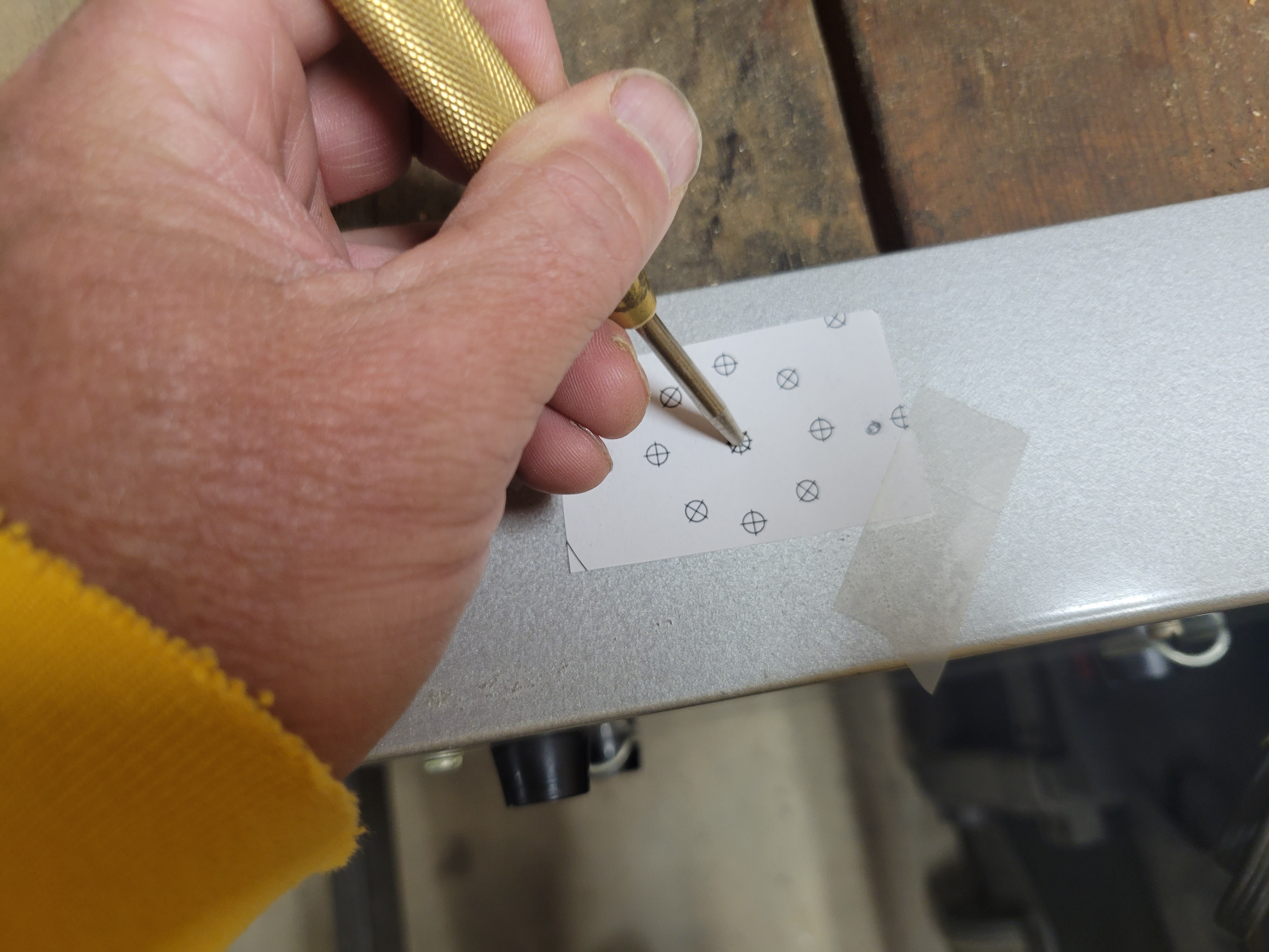
Next, you'll use a punch to notch the locations you will drill holes.
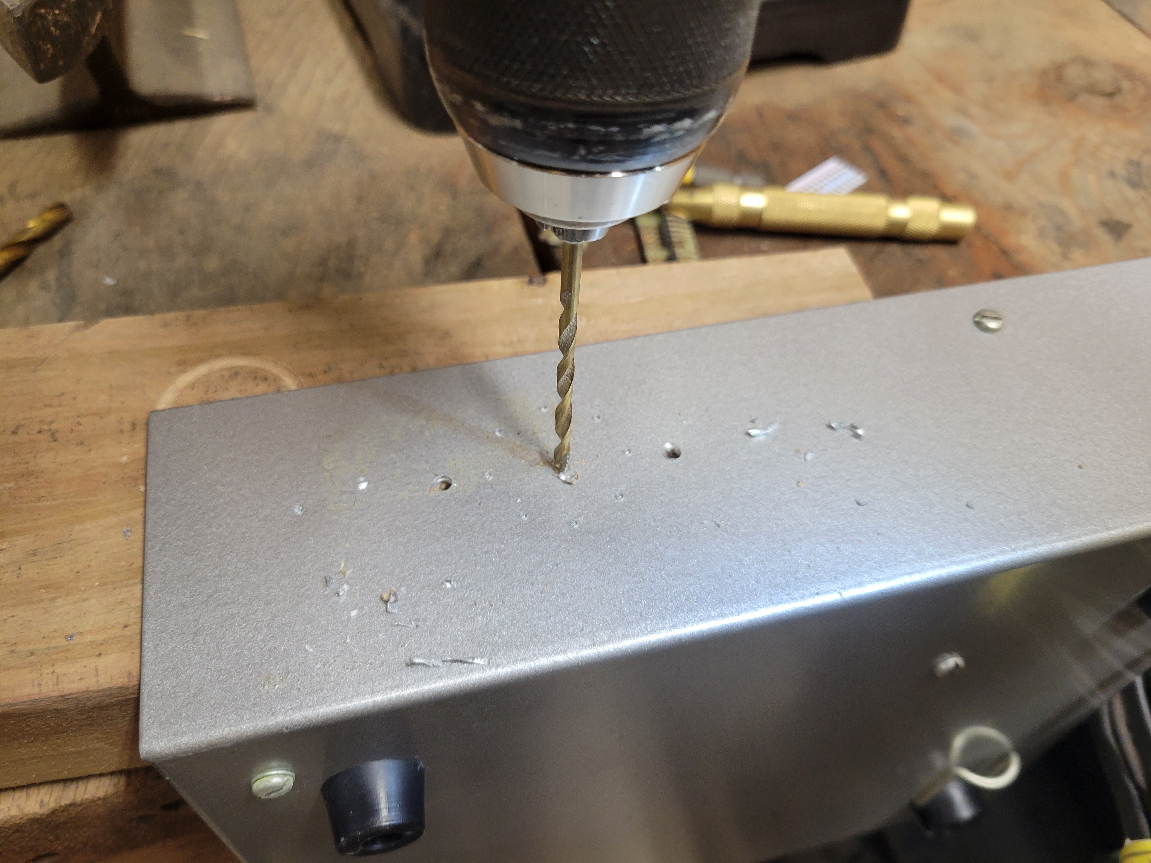
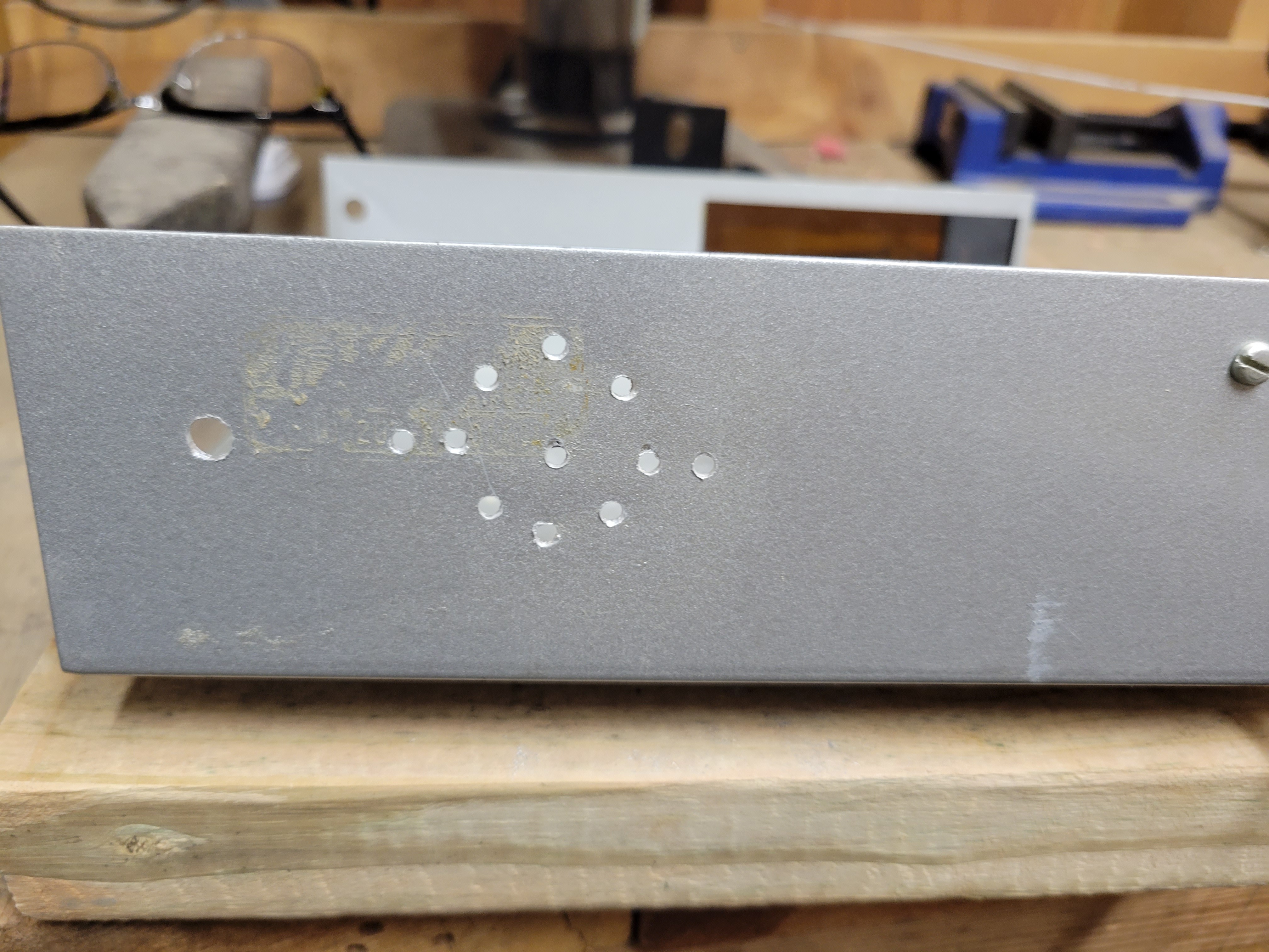
Remove the template and drill the holes. For my install, I drilled 1/8" holes for the speaker sound and mount. And, I drilled a 1/4" holes to mount the on/off toggle switch.
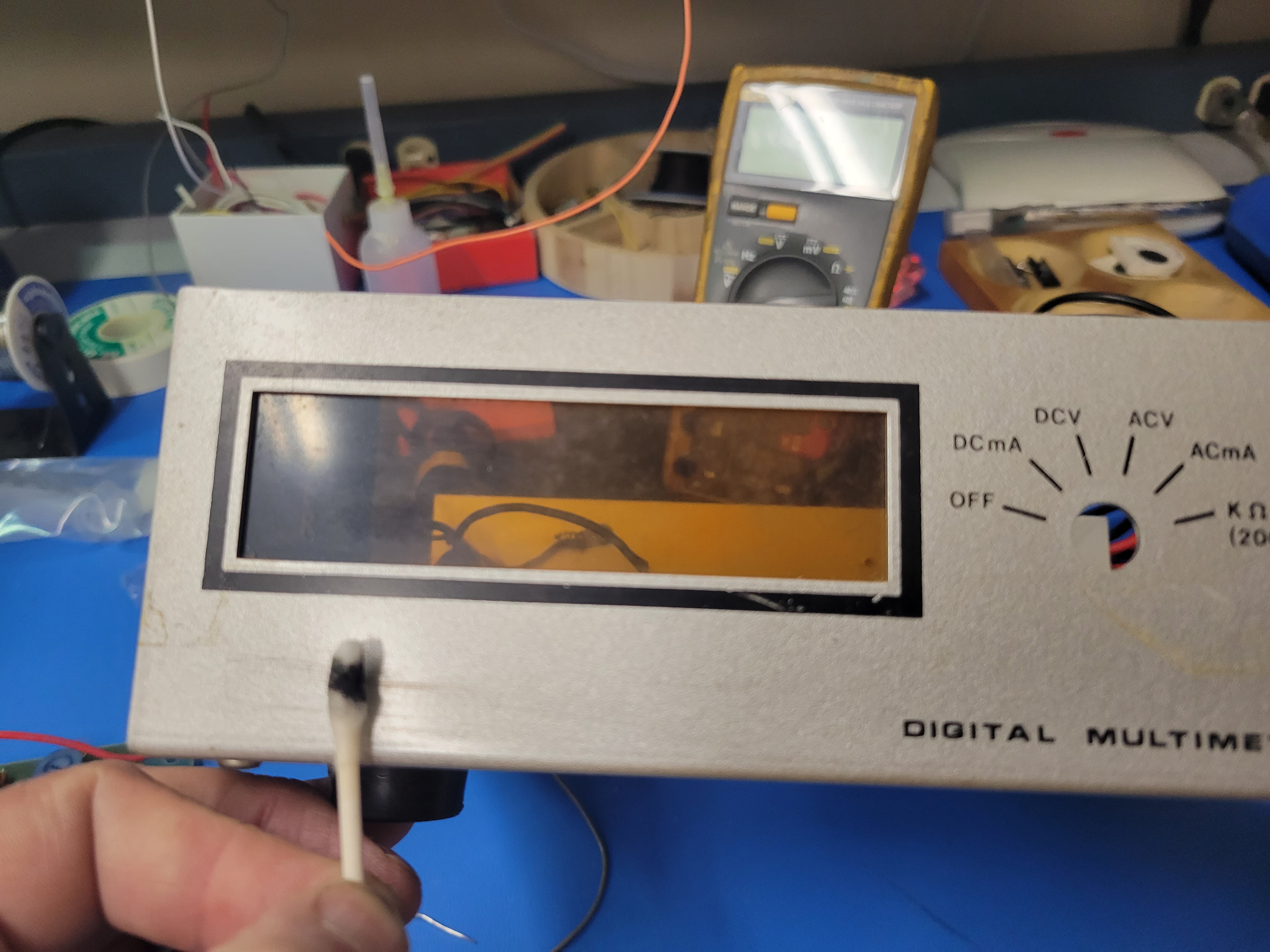
Next, you will remove some of the old graphics on the front faceplate. 100% acetone works great for this. It will remove the black silk screened graphic without damaging the silver painted base. Use q-tips to apply the acetone so you don't get it on your fingers. It will take several q-tips. But, it will all clean off with very little effort. I leave the black printed border around the display window.
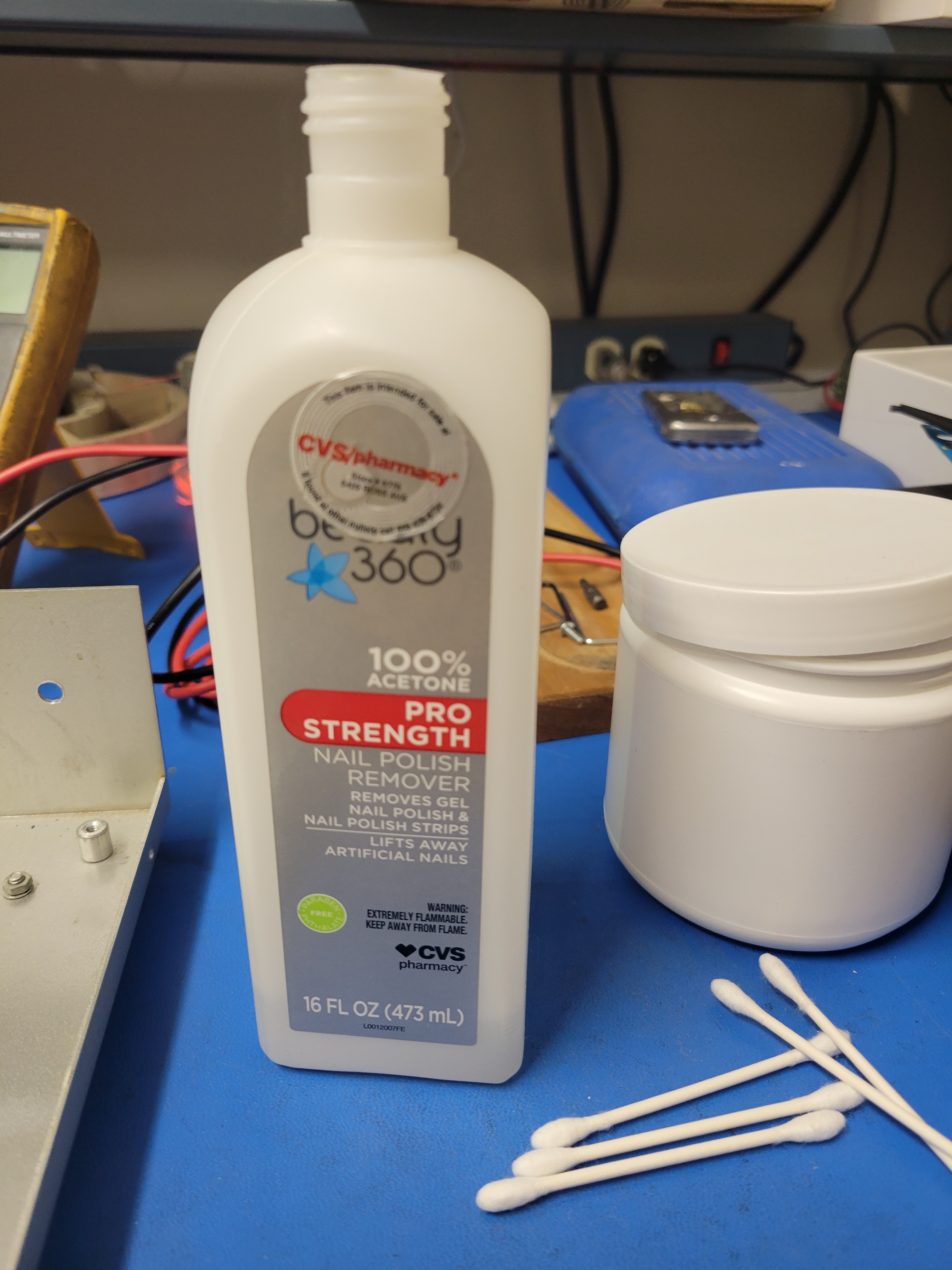
Tip: Pour a little of the acetone from the bottle into the cap to dispense the fluid onto the q-tips.
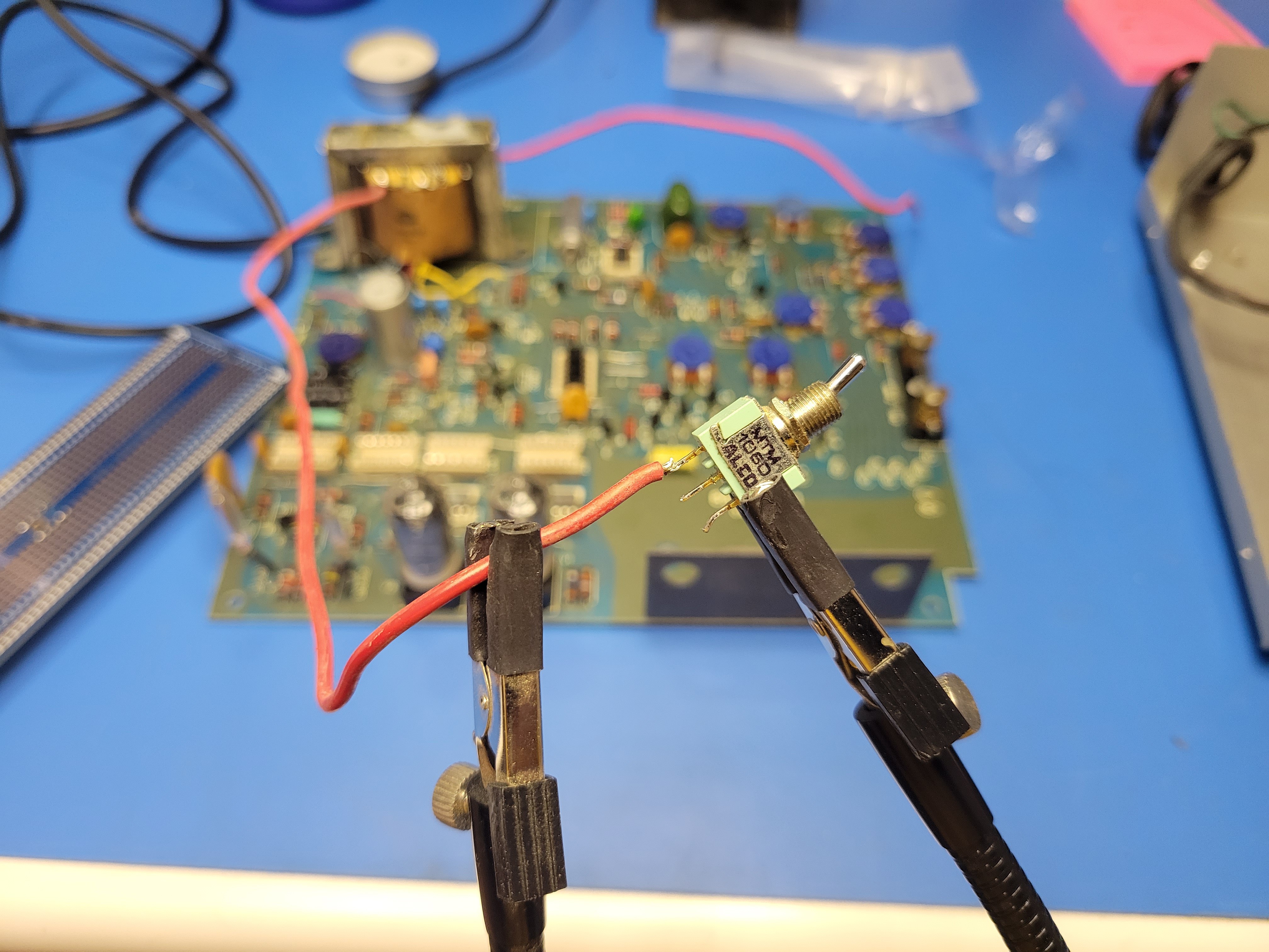
Before re-assembling the PCB and the base of the case, solder the red power wires to the toggle on/off switch.
Now reinstall the PCB into the base of the case using the five screws you removed before and install the toggle switch to the rear of the case.
Lastly, re-solder the power cord wires back to the lead on the transformer and the fuse.
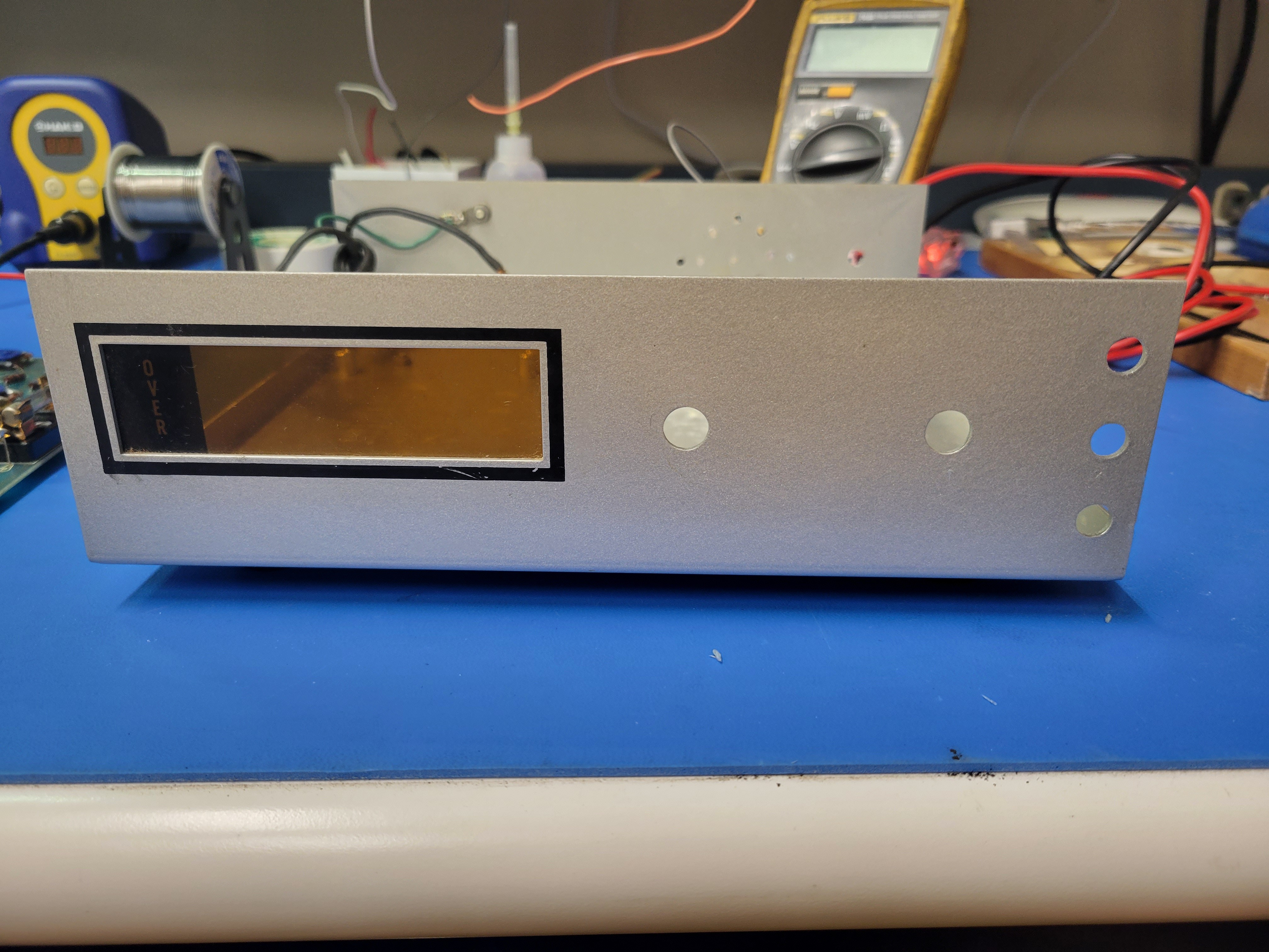
It should look like this when you are done.
You are now ready to start building the controller board.
Discussions
Become a Hackaday.io Member
Create an account to leave a comment. Already have an account? Log In.