 Guillermo Perez Guillen
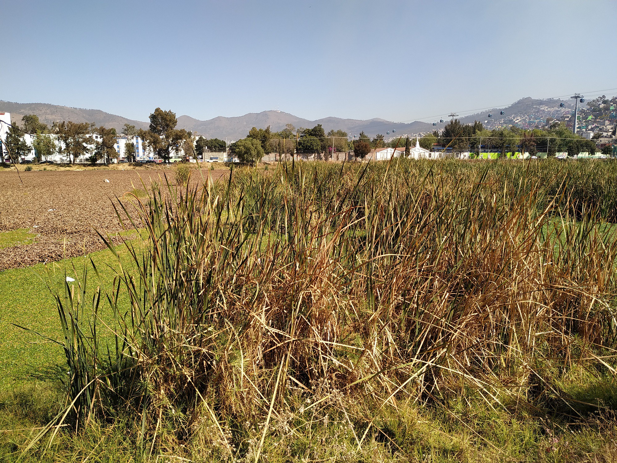
Air pollution has a number of negative impacts on the environment, including damage to human health and natural ecosystems. The World Economic Forum has stated that air pollution is the ‘deadliest form of pollution’, while the World Health Organization claims that in 2016 over 92% of the world’s population reside in places where air pollution exceeds health and safety limits. Despite these unbelievable facts, some countries - like the UK, US, Australia and New Zealand - are seeing a decrease in the amount of air pollution. Although urban green spaces are not solely responsible, it’s undeniable that these areas have contributed to the overall decline.

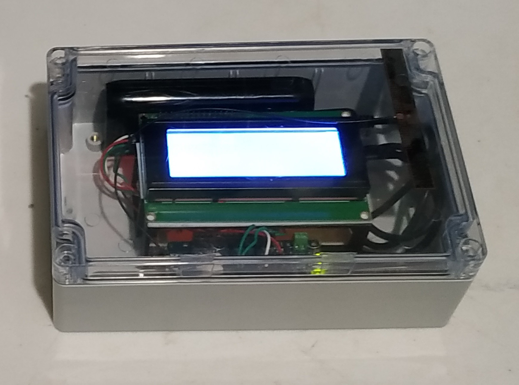
How does it works?
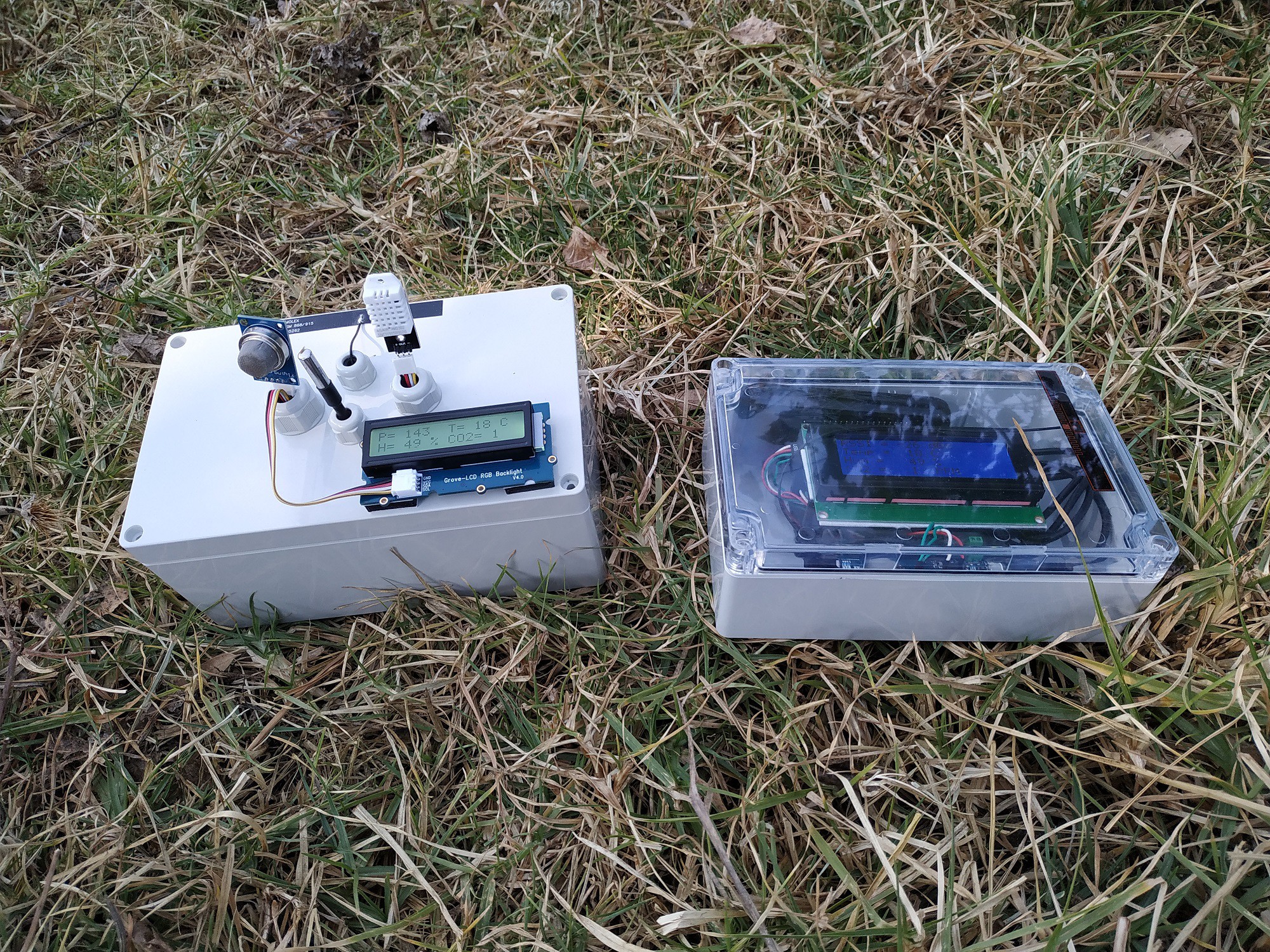
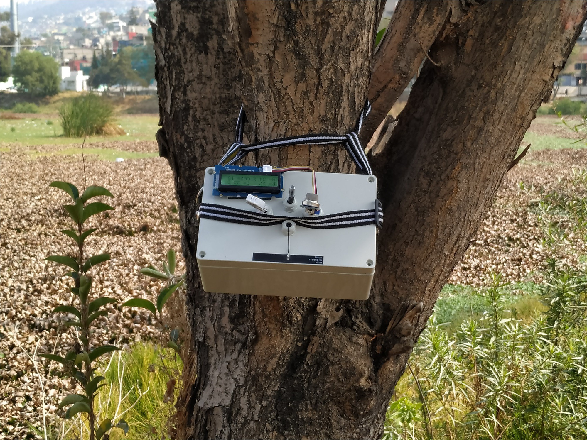
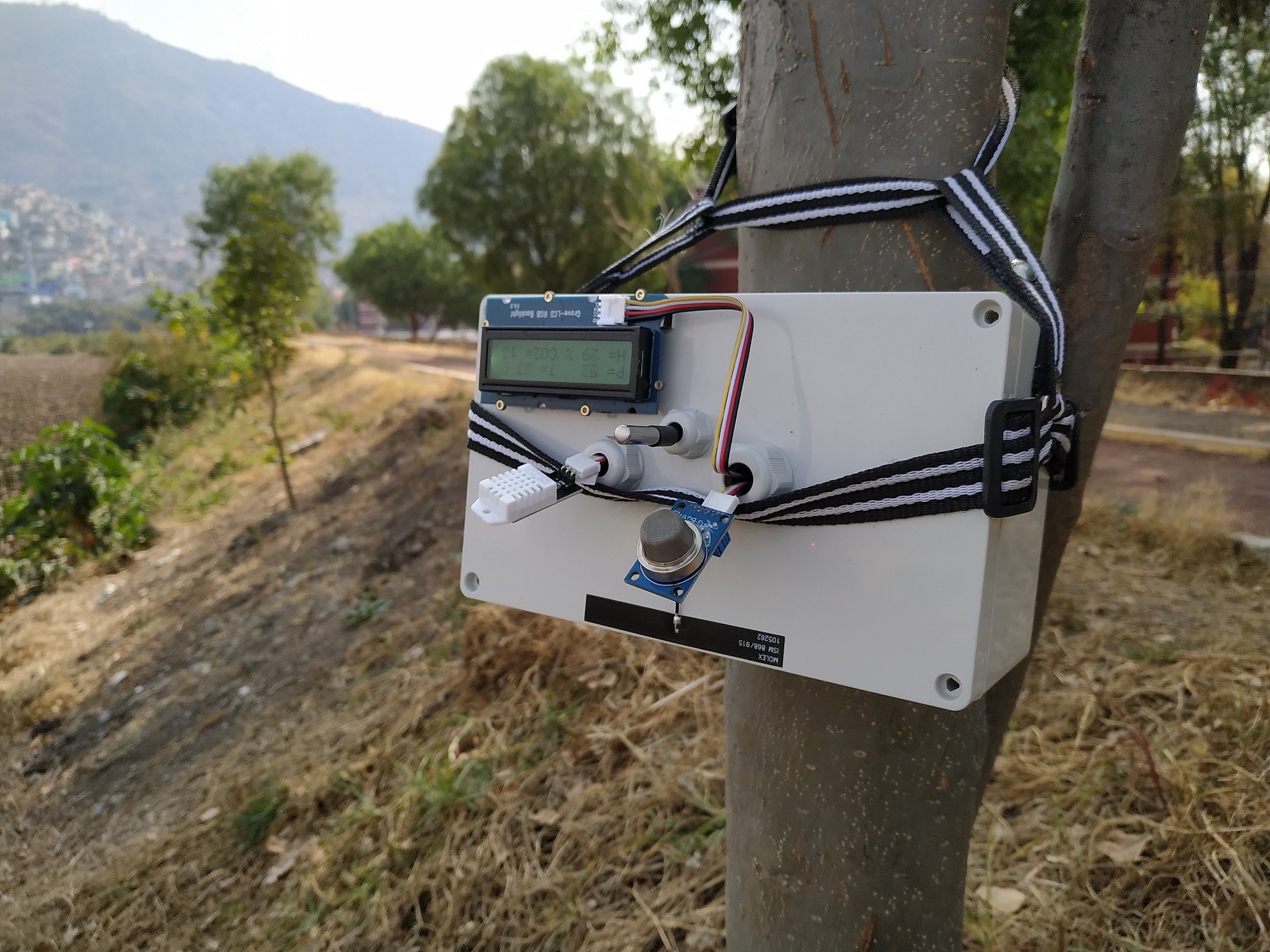
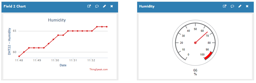
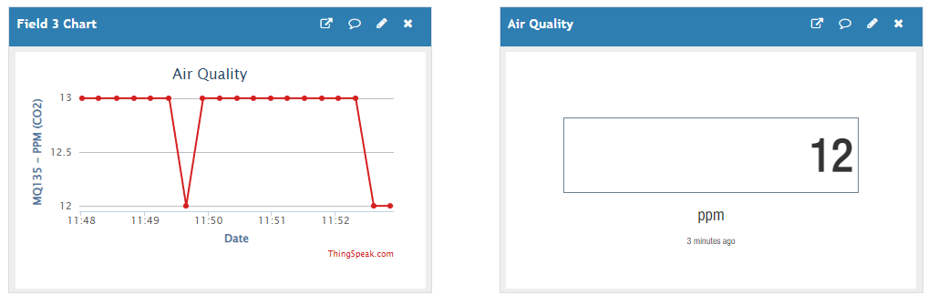
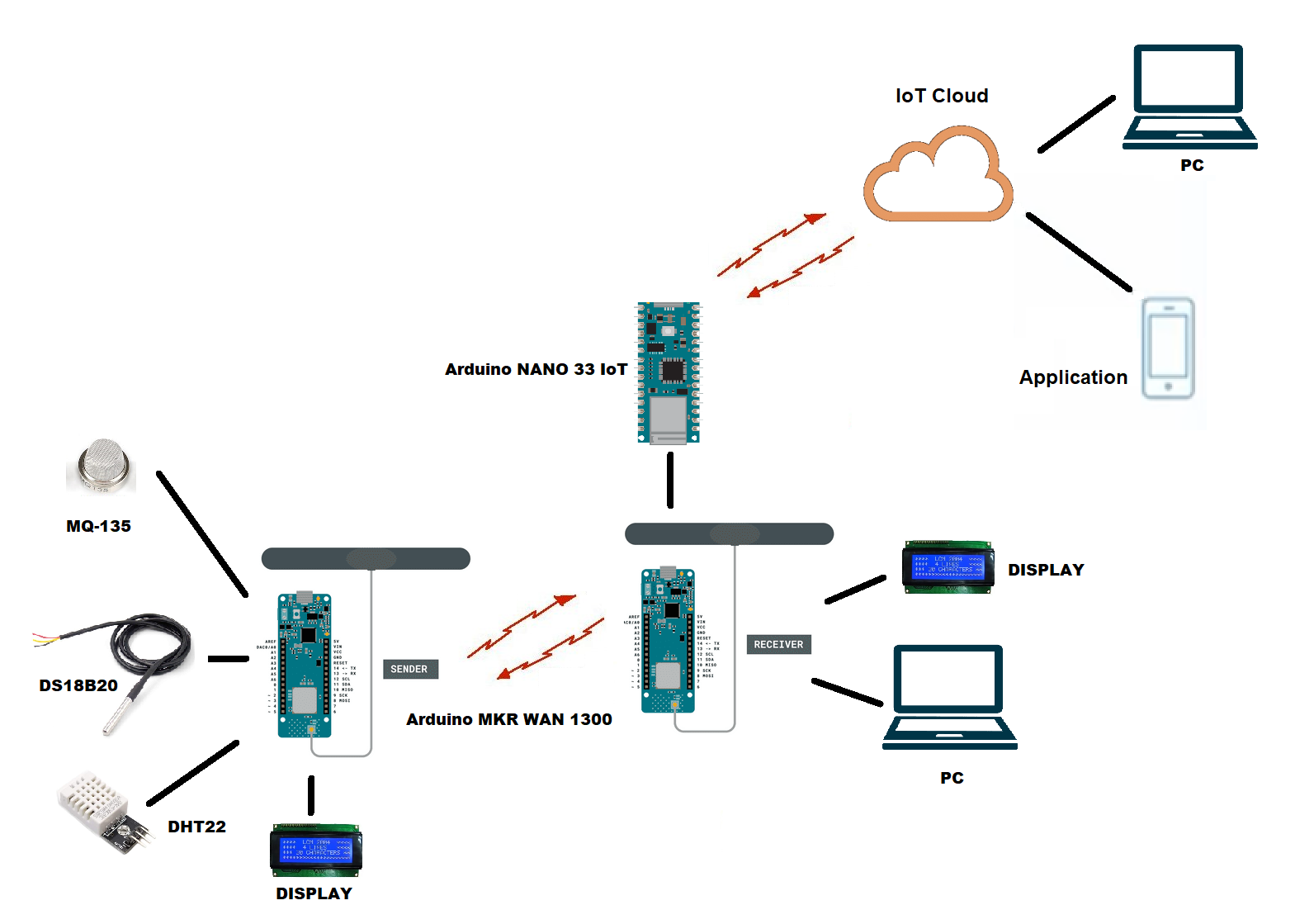
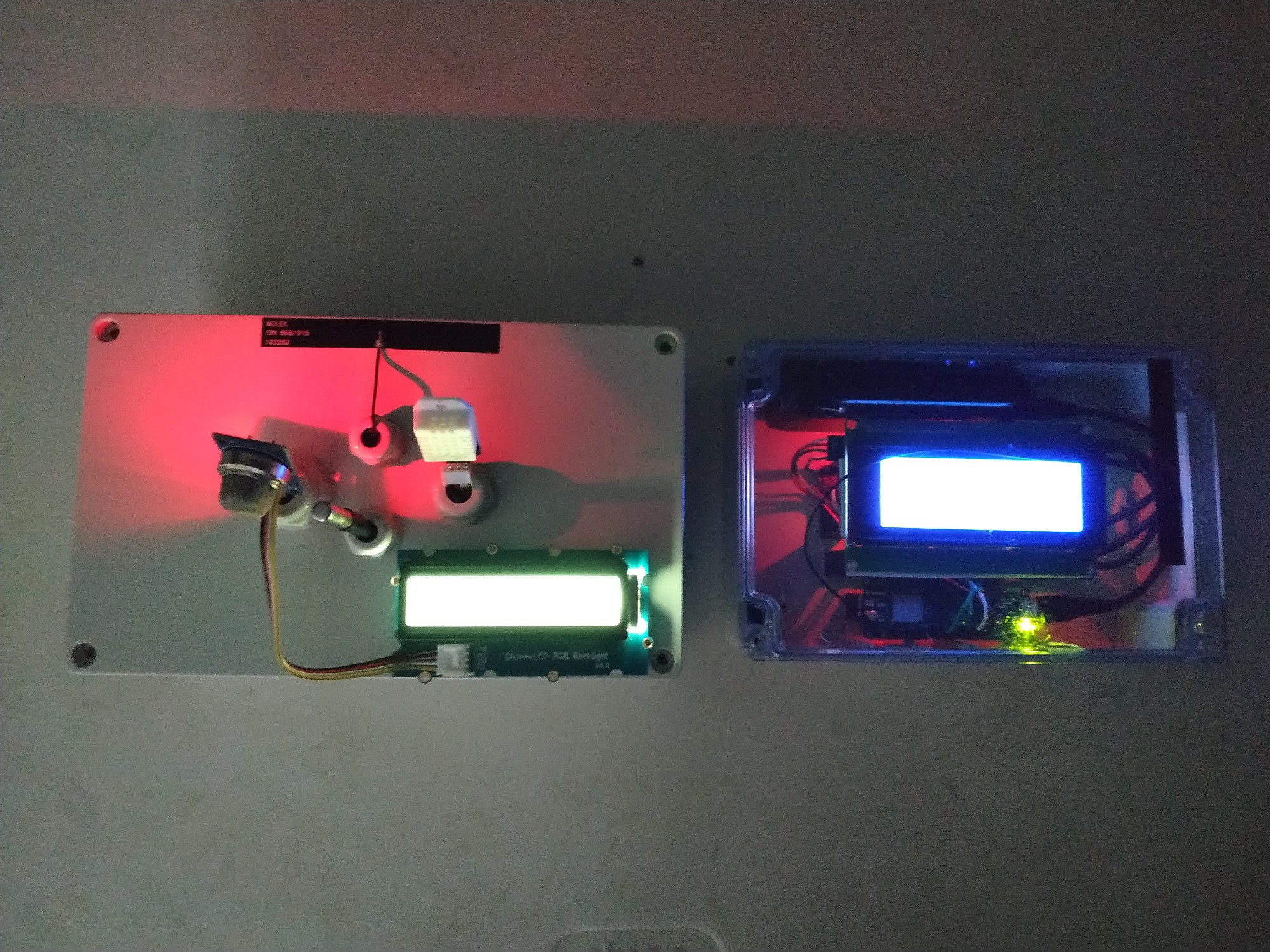
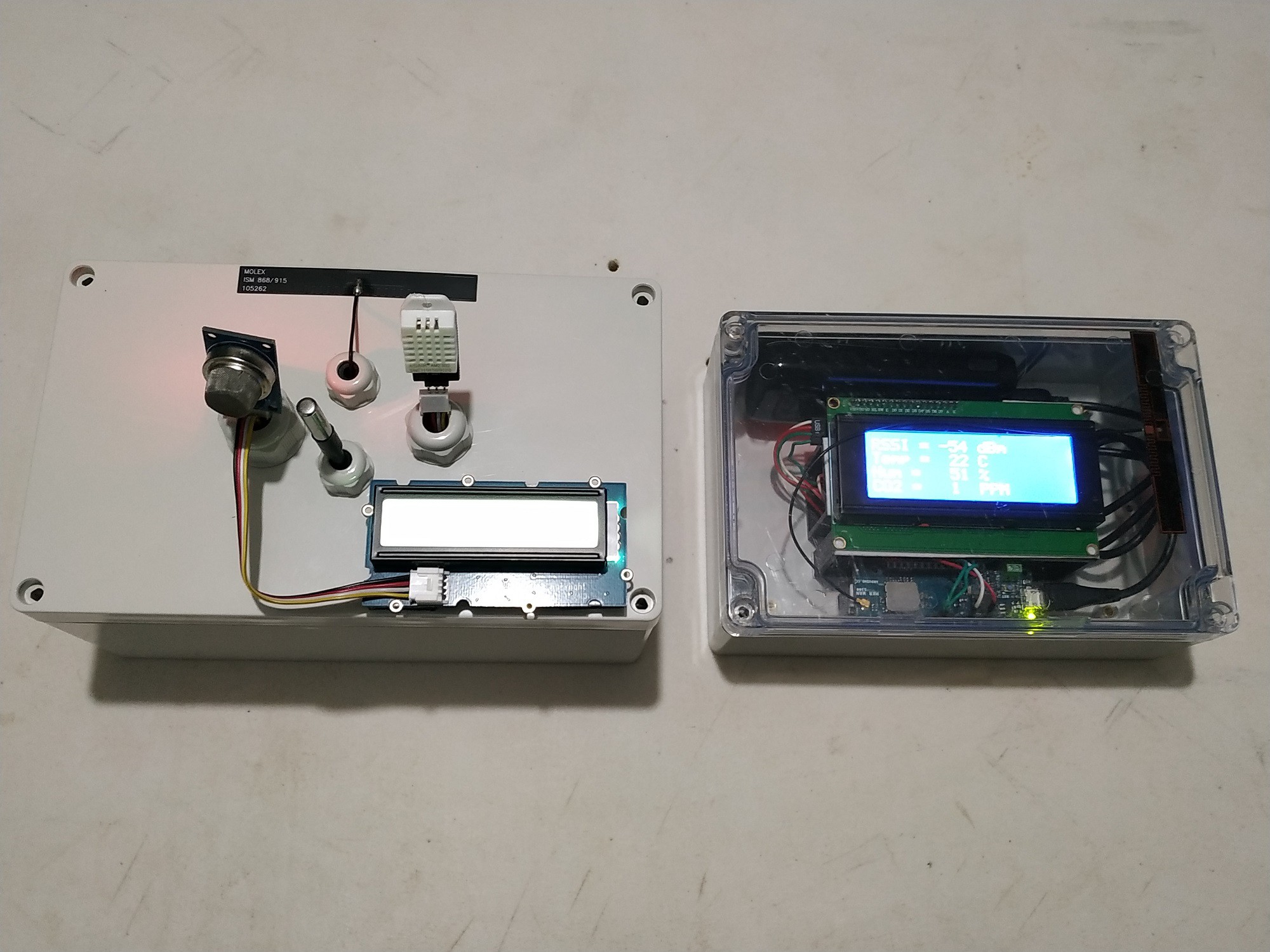
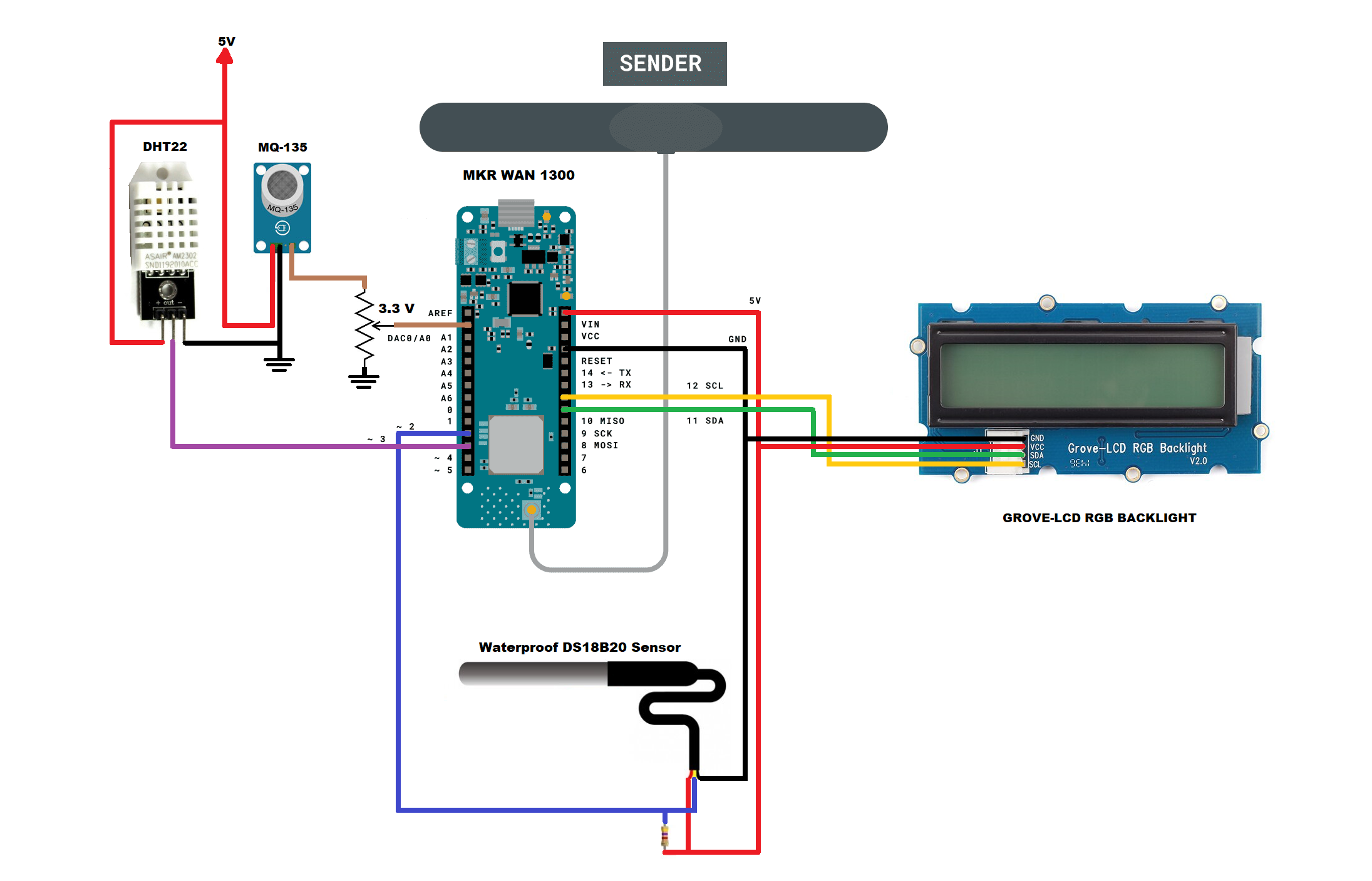
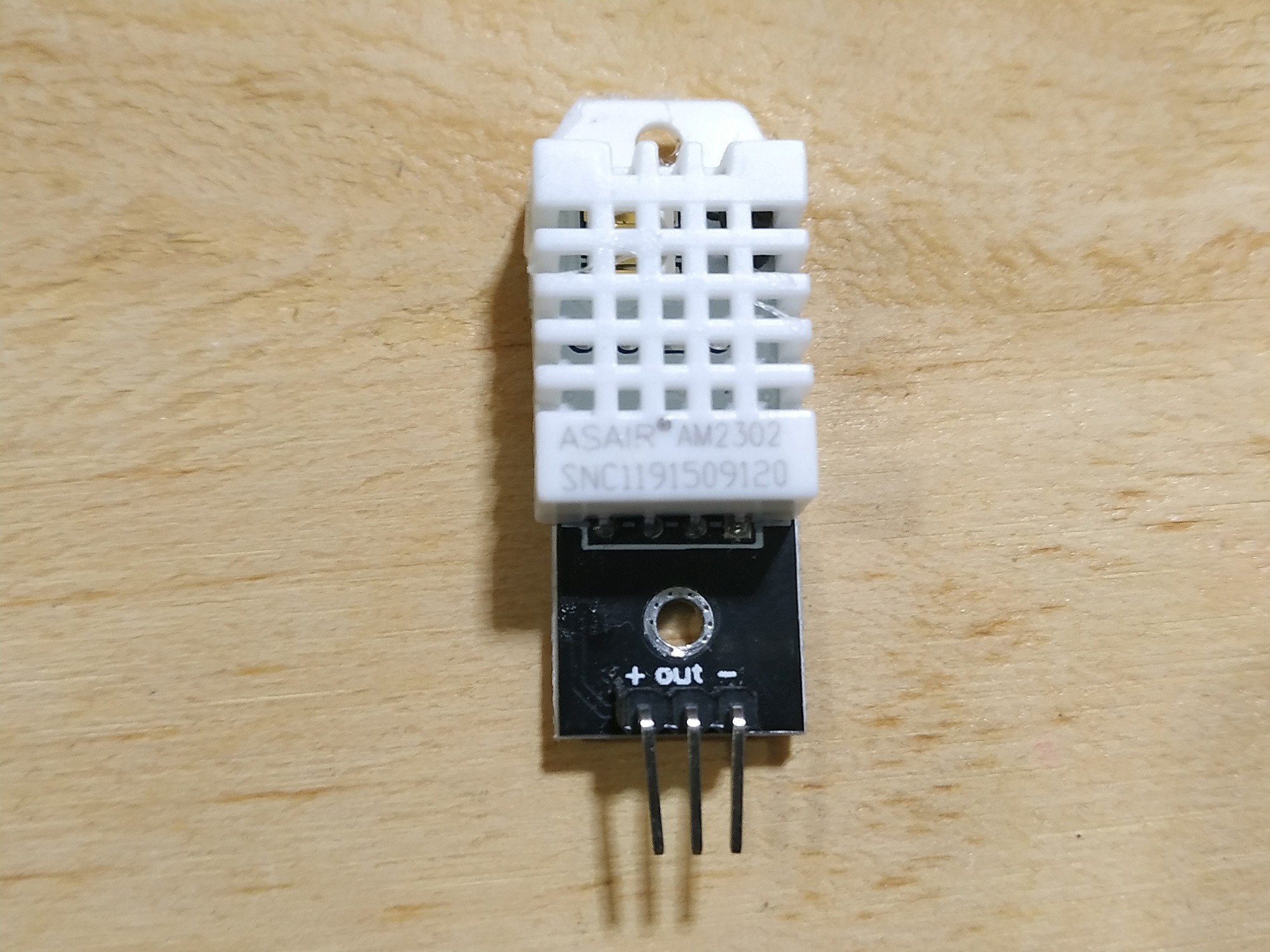
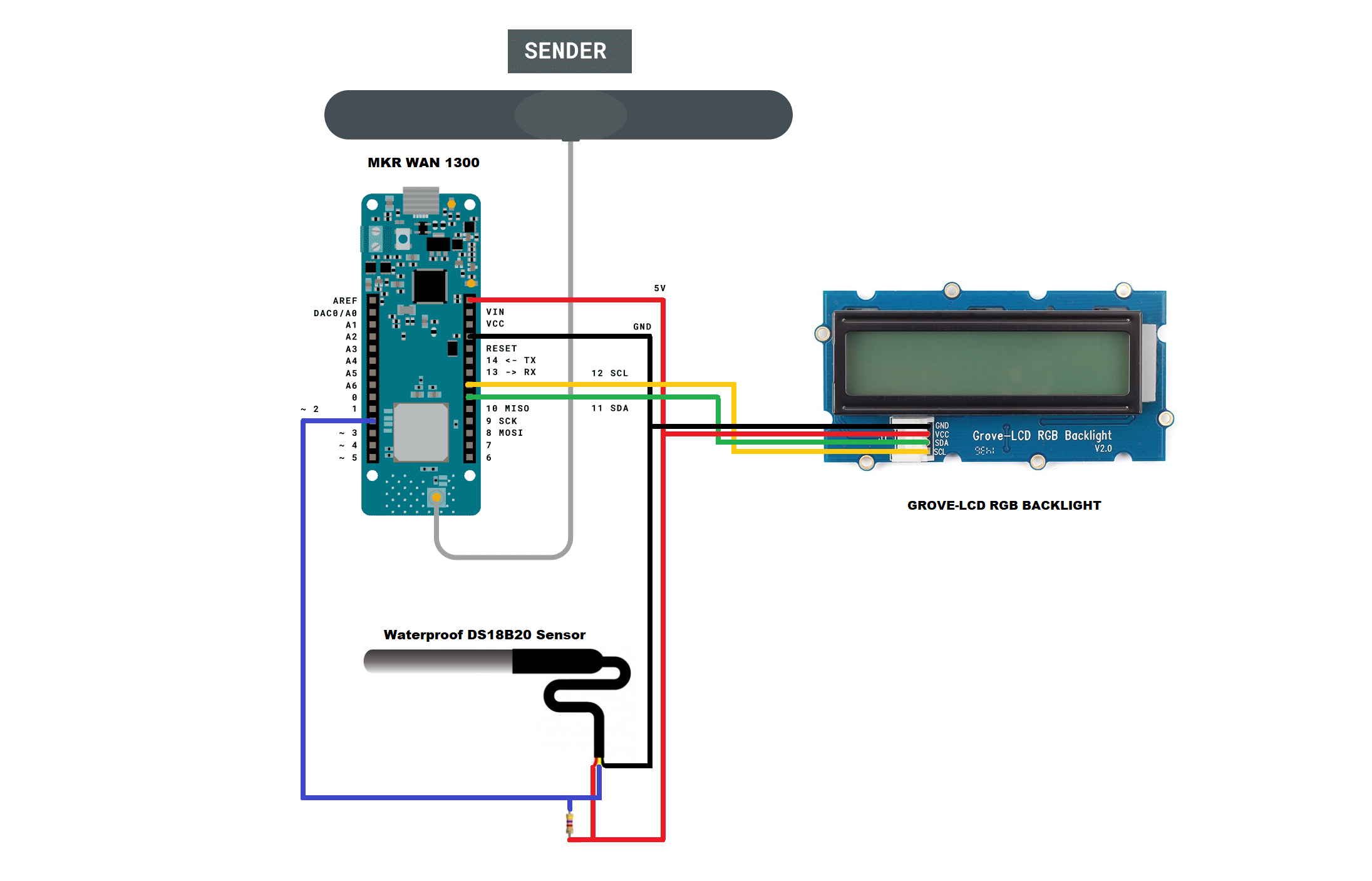
- I collect data with sensors such as: Humidity, temperature, Carbon Monoxide, Carbon Dioxide, Volatile Organic Compound (TVOC), Smoke, water level, etc;
- I select and pre-program the time intervals when the system is monitored, and then it go into low consumption for energy saving;
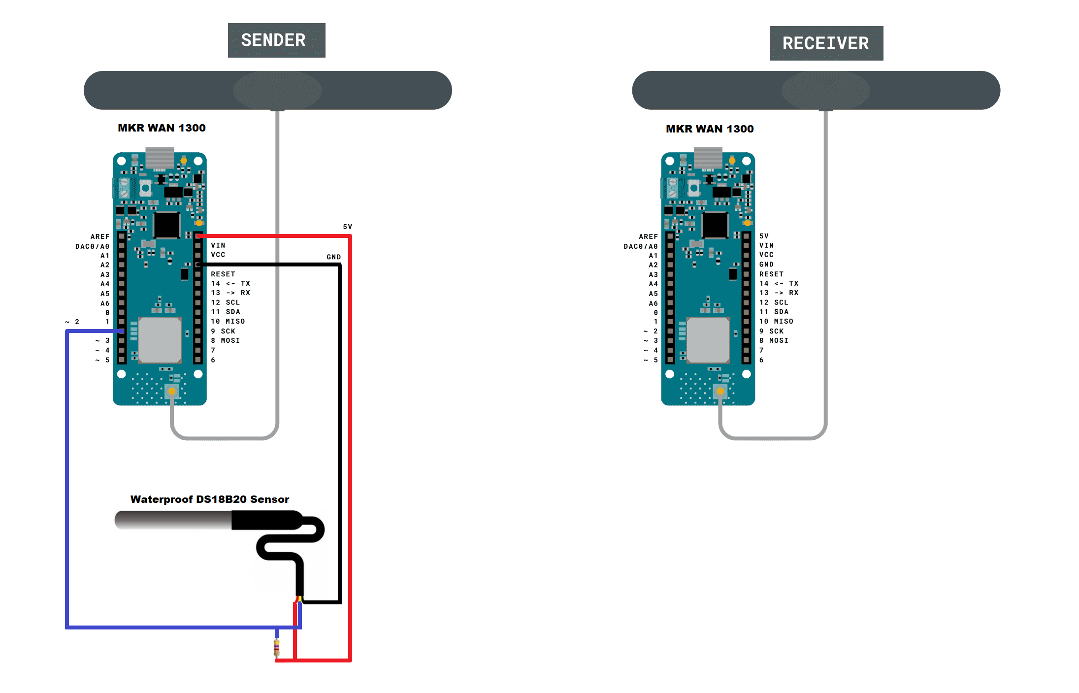
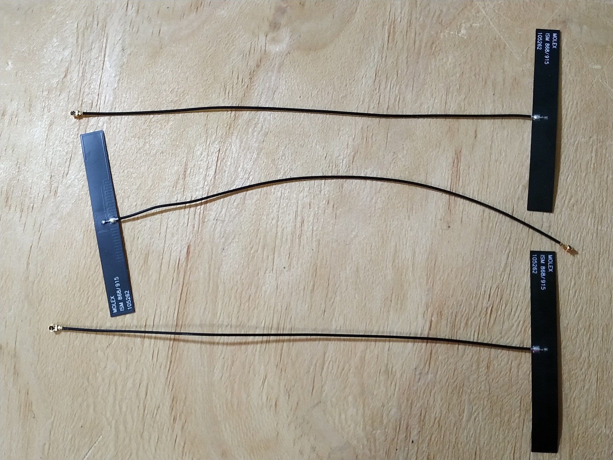
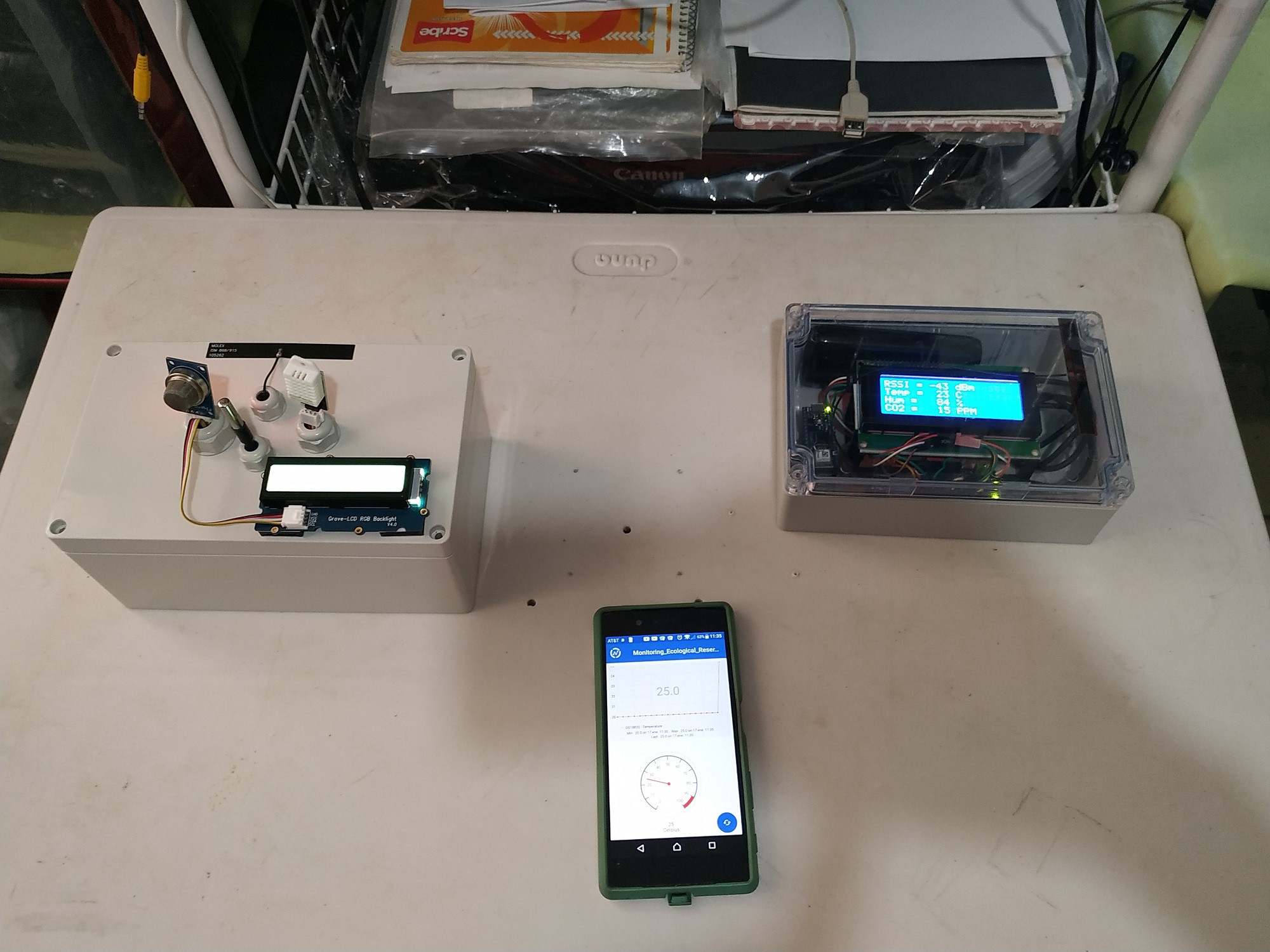
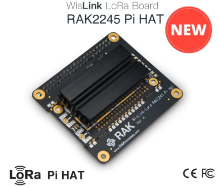
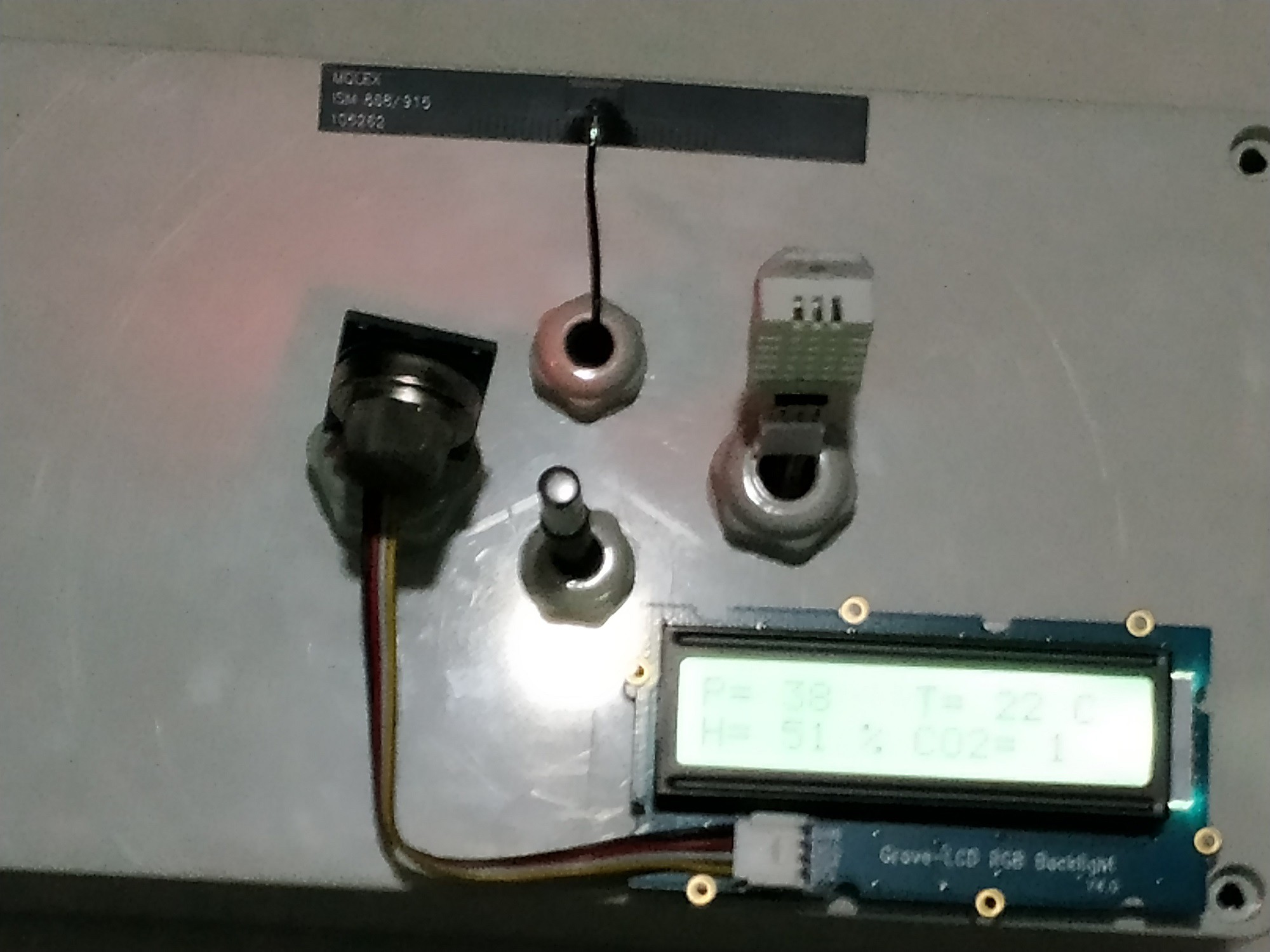
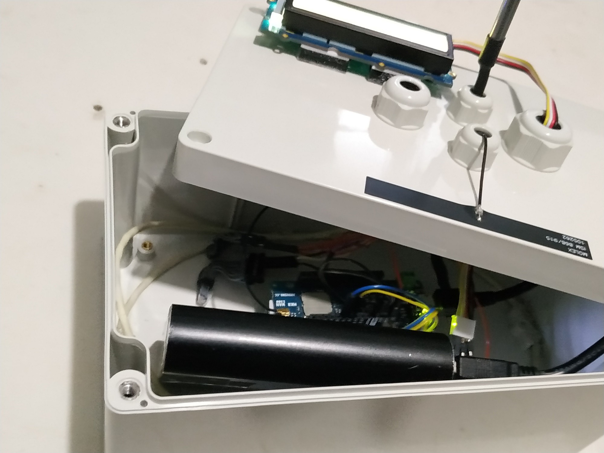
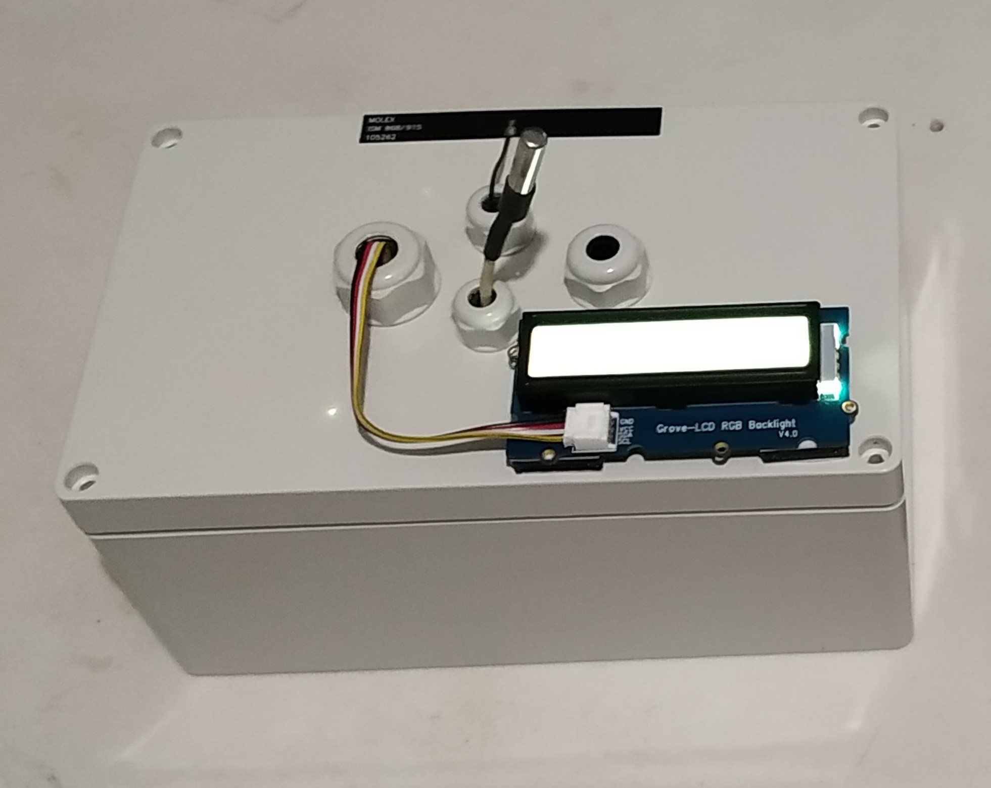
- I'm using connection via RF through Carrier frequency LoRa (433/868/915 MHz)
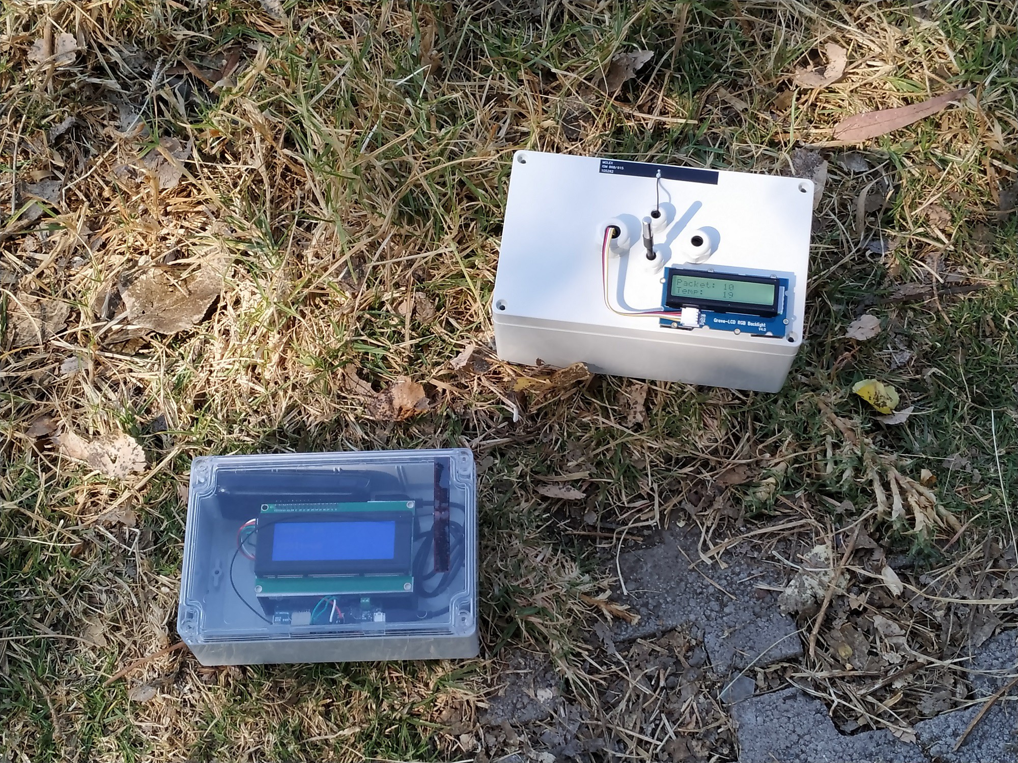
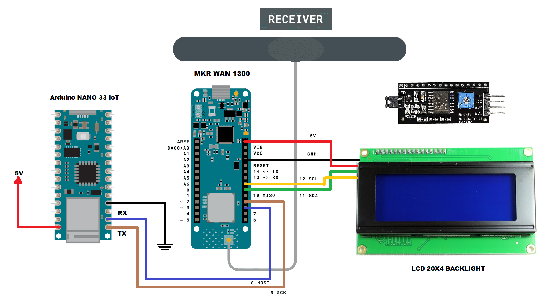
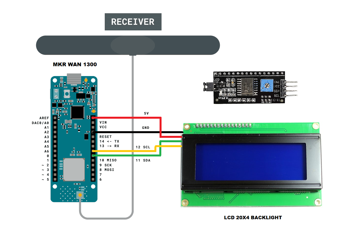
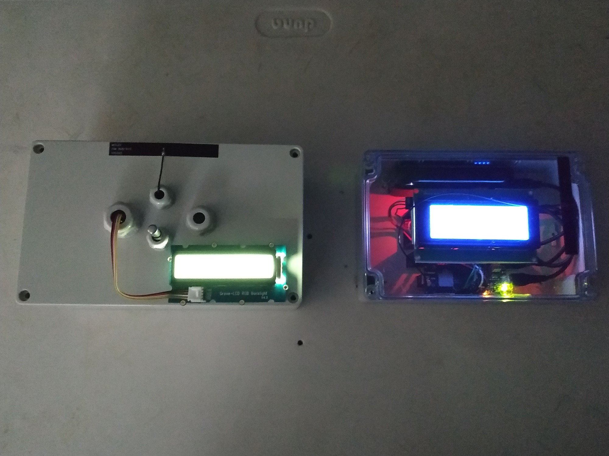
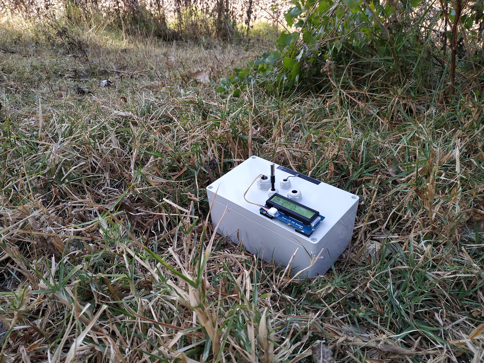
- I read the captured data and activate alarms to be seen on an LCD screen or on a Laptop or a PC.
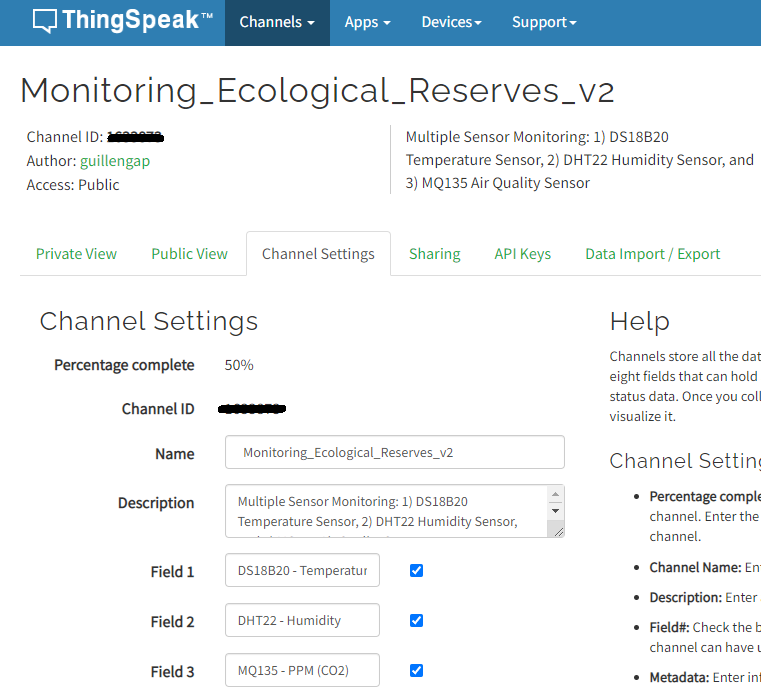
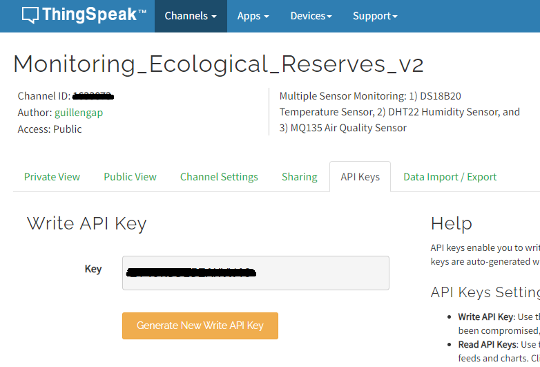
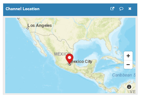
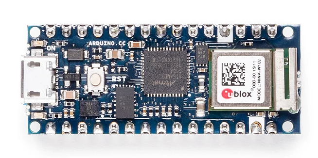
- Additionally, this system connects to the cloud of an IoT server through an Arduino NANO 33 IoT board.
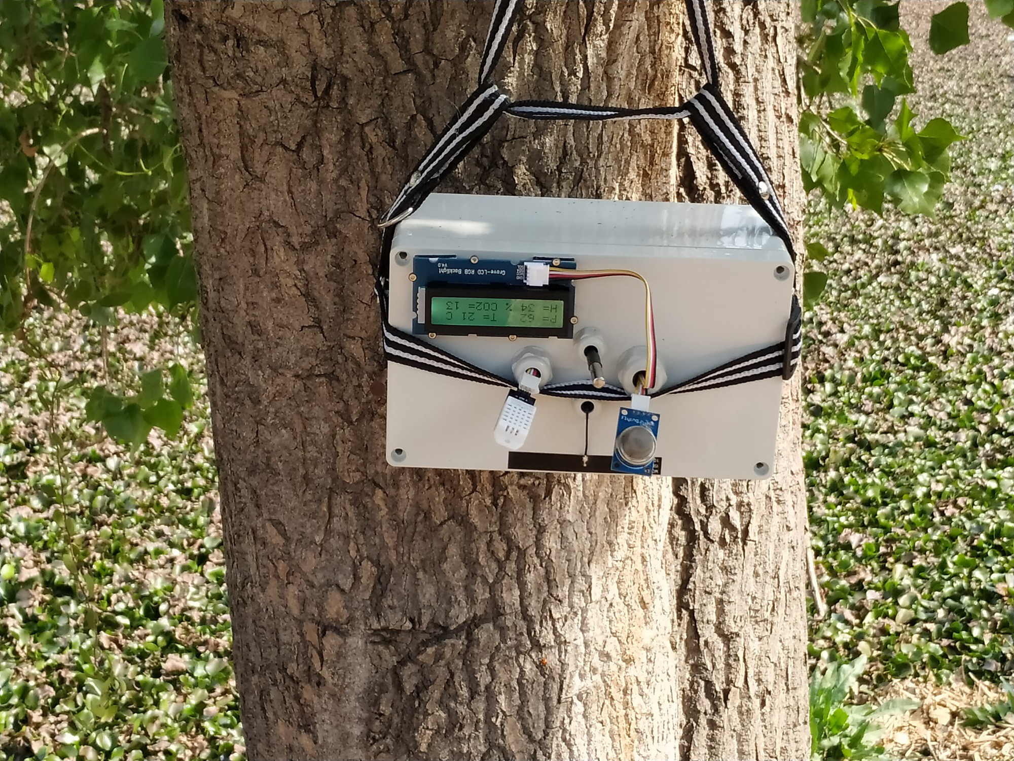
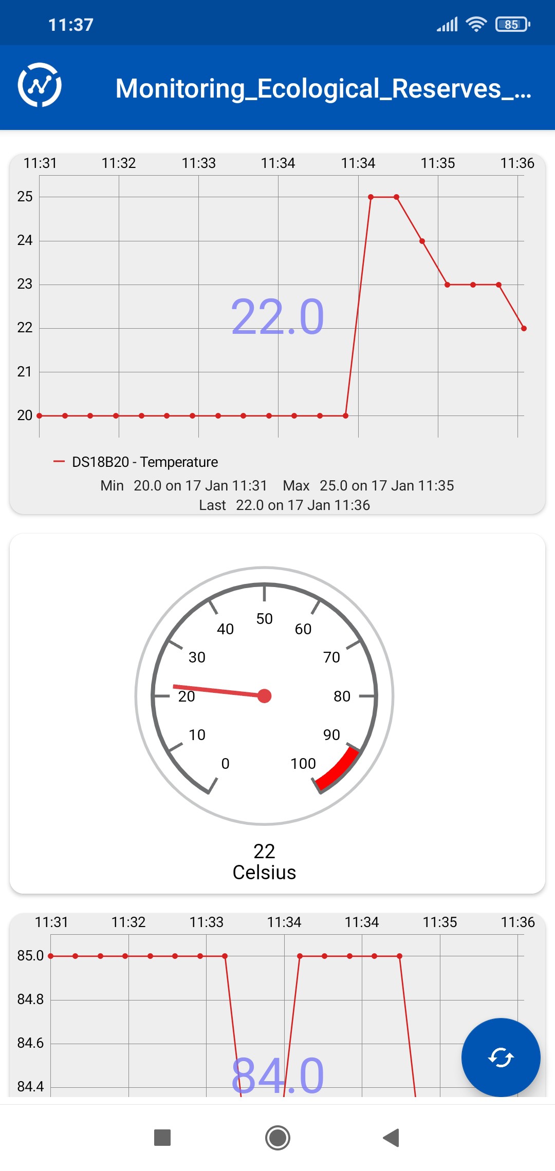
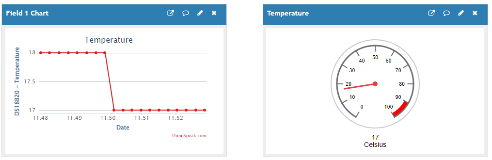
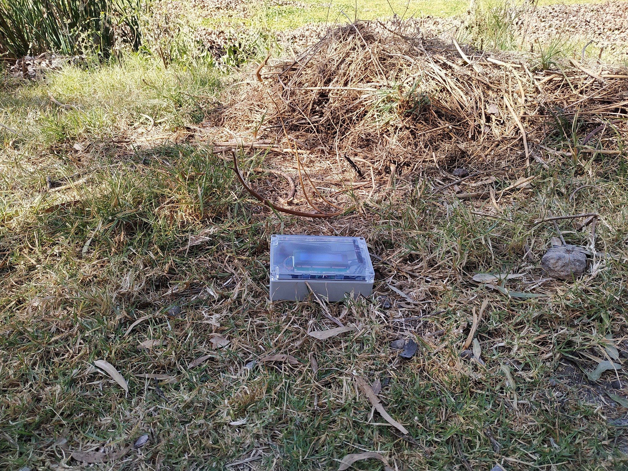
Below I show you a demo of this project in action.
I want to thank all the people who have seen this project, those who like it, and the followers. Above all, I want to thank Hackaday for giving me the chance to make one of my dreams come true.


 Tom Meehan
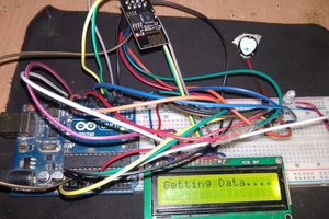
 electronicsworkshops
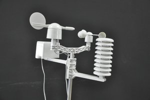
 muzi
muzi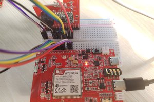
 Makerfabs
My project is an innovative and hardware tangible solution, since I'm using open source to help solve sustainability. climate resiliency, and circularity of one of our planet's most pressing issues.