 ElectronicABC
GERBER PCB:
https://mega.nz/file/XJQ03LwK#lN3Bj5L8-eLIjZEa-PF0Qq8FnKCUWxYYCXx-TZeNqro
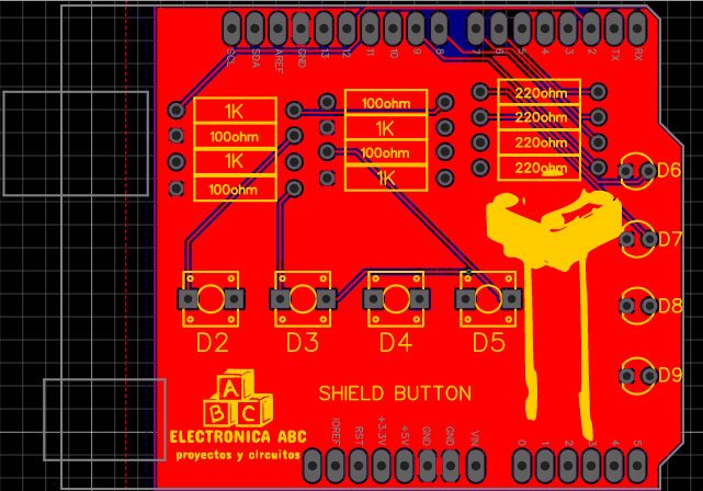
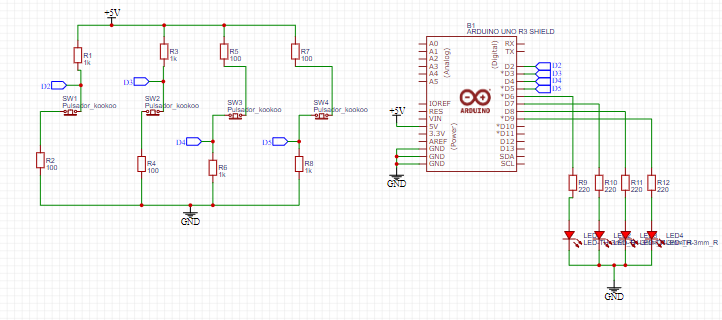
In this project we will make a PCB of a shield button for programming tests using the ladder language for PLC.
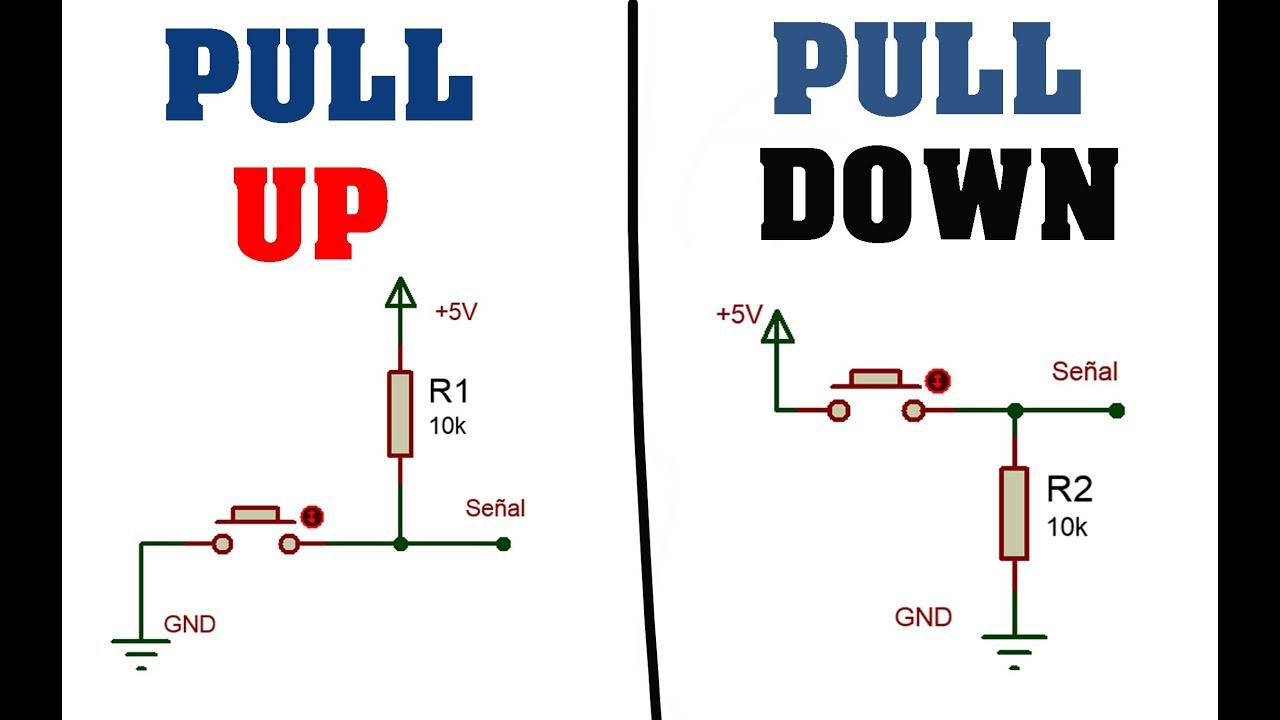
We will use the PULL UP and PULL DOWN configuration to send signals like NO and NC to the ARDUINO UNO and we will use the LDMICRO software to program it using the LADDER language.
LENGUAJE LADDER:
Ladder language, ladder diagram, contact logic/diagram, or ladder diagram, is a very popular graphical programming language within programmable logic controllers because it is based on classic control electrical diagrams. In this way, with the knowledge that every electrical technician or engineer possesses, it is very easy to adapt to programming in this type of language.
Ladder is one of several programming languages for programmable logic controllers (PLCs) standardized with IEC
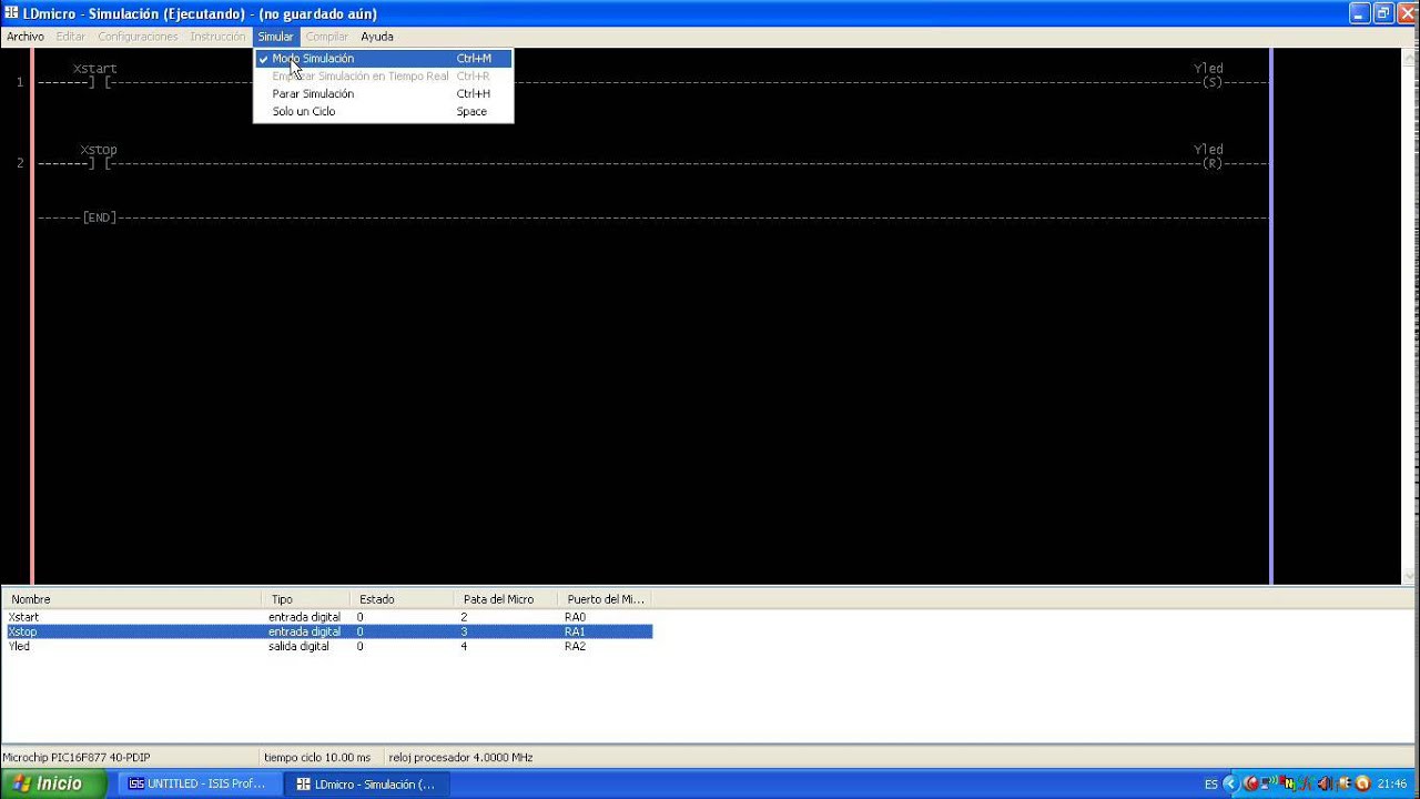
LDMICRO:
t is a ladder language programming software for microcontrollers (ARDUINO UNO, MEGA, NANO and other pic microcontrollers) where we can generate the ARDUINO IDE or HEX file to burn or pass the code to our microcontroller.
ELECTRONIC COMPONENTS:
· 4 RESISTORS 1/4W 220 ohm
· 4 RESISTORS 1/4W 10K ohm
· 4 RESISTORS 1/4W 1K ohm
· 4 PUSH BUTTON 2 PINS
· 4 LED DIODES 3MM RED
· 1 BLADE (40 PINS)
· 1PCB
FEATURES:
· VIN 5VDC
· IMAX 80mA
· 4 inputs (2 pull UP – 2 pull DOWN)
· 4 DIGITAL OUTPUTS
· LADDER OR LADDER PROGRAMMING
HERE WE LEAVE THE LADDER LANGUAGE AND ARDUINO IDE FOR THE REAL SIMULATION OF A DIRECT STARTUP THROUGH LDMICRO AND ARDUINO IDE.
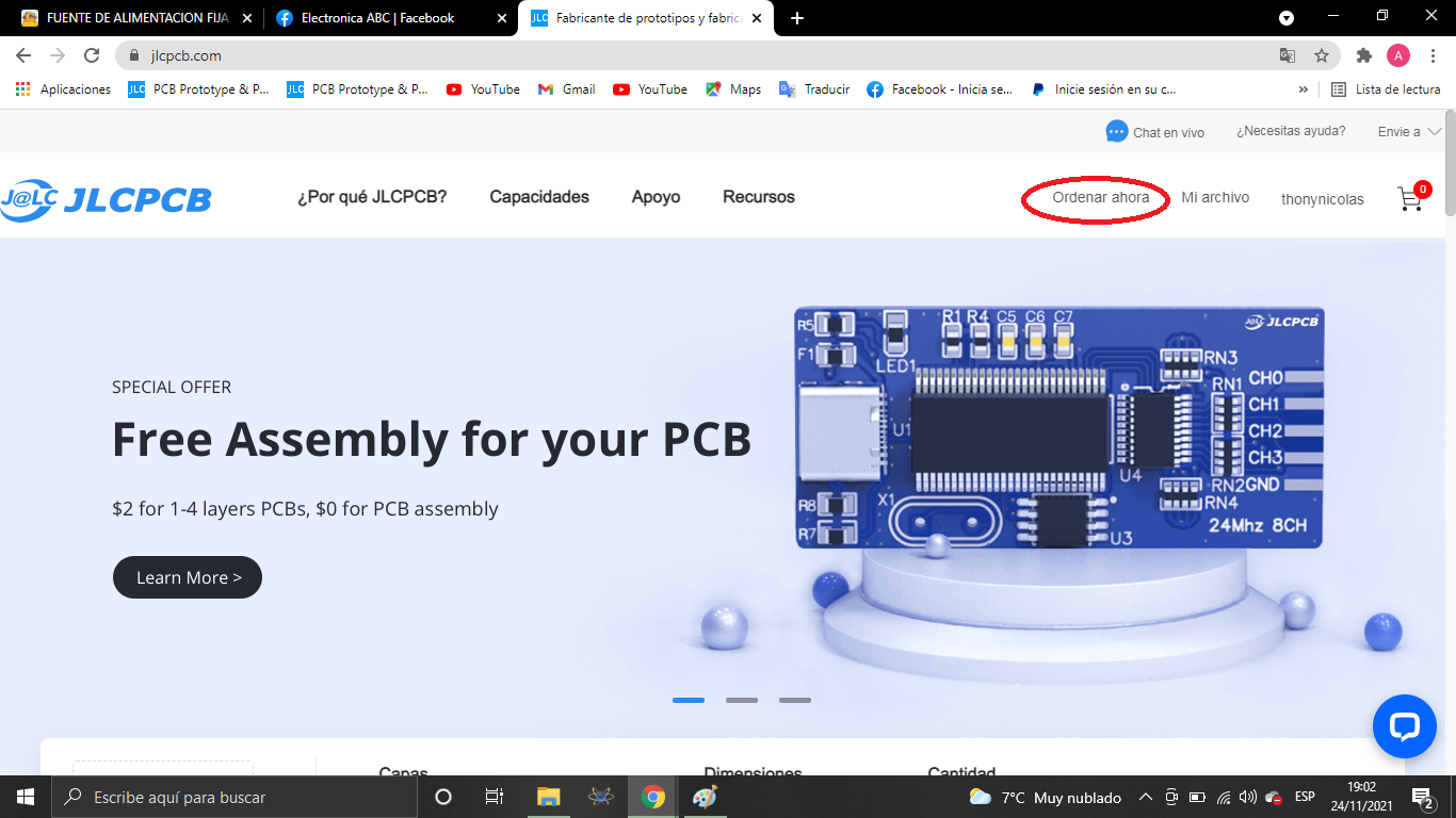
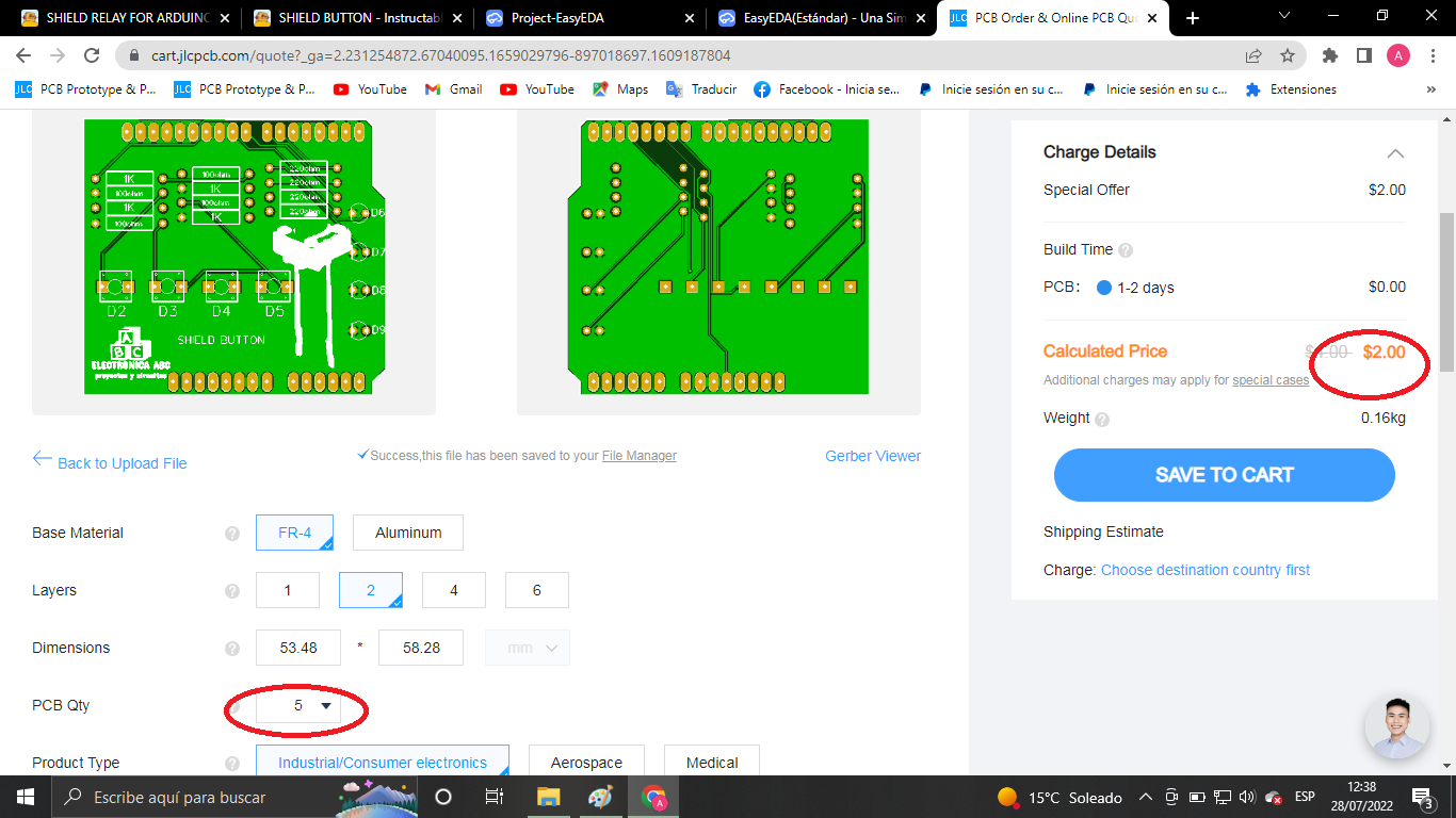
We thank JLCPCB for professional PCBs
Order your PCBs here
5PCBS AT $2
GERBER PCB:
https://mega.nz/file/XJQ03LwK#lN3Bj5L8-eLIjZEa-PF0Qq8FnKCUWxYYCXx-TZeNqro

 Jithin Sanal
 featheroffalcon
 Lithium ION