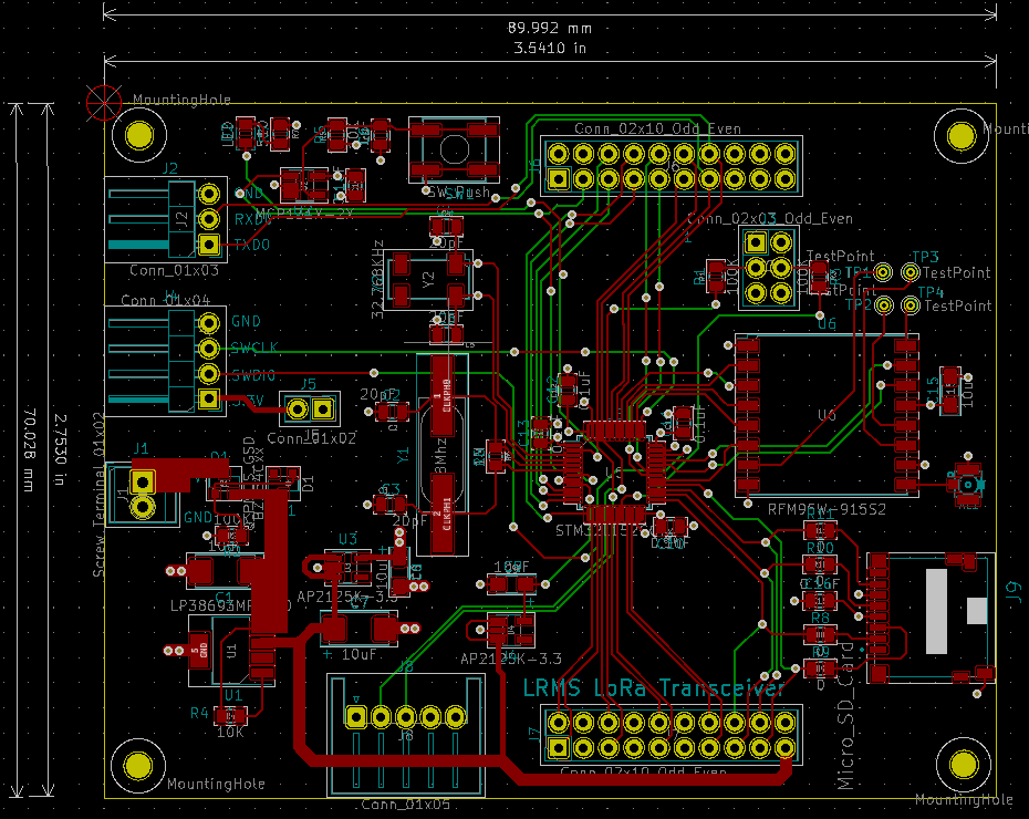
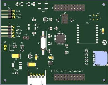
LoRa Transceiver
-------------------------
-Input Voltage:
5.2 - 10 VDC
Reverse polarity input protection (R2)
STM32L15X
256K Flash Memory
32K SRAM
RTC Support - 32Khz Crystal
RS-232 3.3V TTL Debug Port
ST-LINK SWDIO Programming header
Transceiver : HopeRF RFM95W US 915Mhz FCC certified
- I/O
I2C-1
I2C-2
UART1
UART2
ADCs: ADC6,ADC7,ADC8,ADC9
DACs: DACOUT1, DACOUT2
GPIO:
- Power Rails
5V Digital
3.3V Digital
3.3V Analog
Load Current: 500mA Max
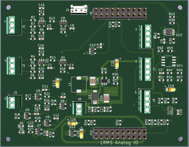
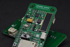
LoRa I/O Board
----------------------
- 3x 1x12 screw terminal blocks to connect to sensor modules via:
I2C-2
UART-2
SPI-2
ADC/DAC
GPIO
LTC4311 I2C bus accelerator for extended lengths on the I2C-2.
24LC32 EEPROM - static storage for LoRaWan EUI, board ID/type etc.
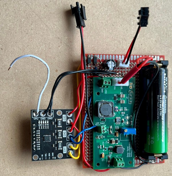
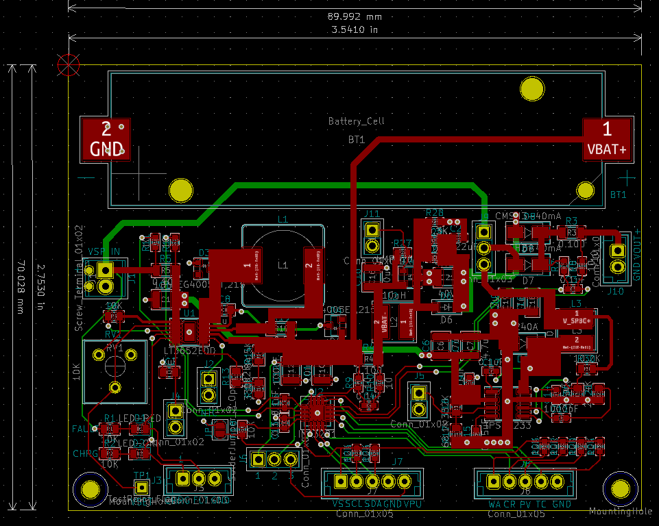
MPPT Solar Power Module (R2)
--------------------------------------------
Panels Supported : 6V to 12V
Charge Rate : 2A Max
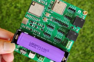
Battery : 3.7V LiPO
Output Voltage : 6.0V No Load
5.6V Load
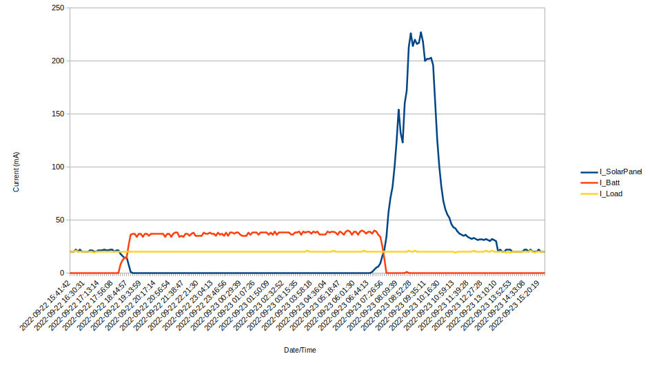
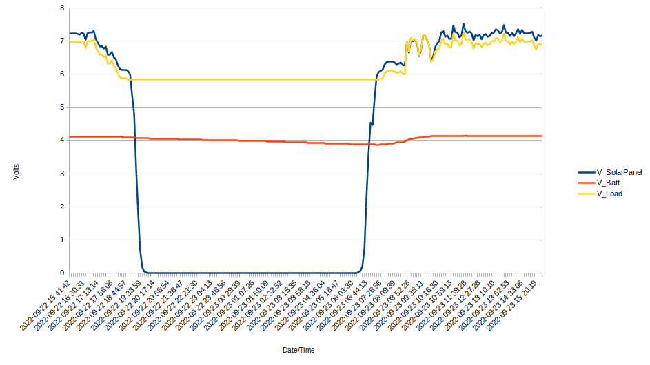
Voltage and Current monitoring of solar panel input, LiPO battery and Output
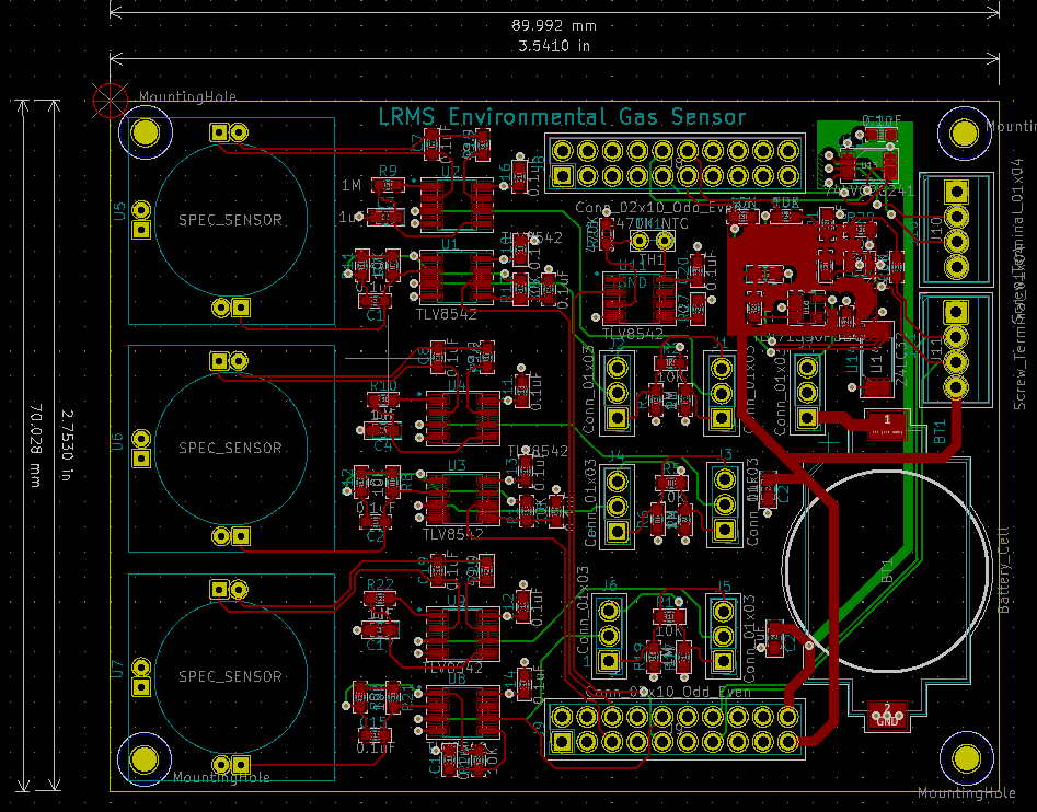
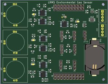 Spec Sensors Electrochemical gas sensor array
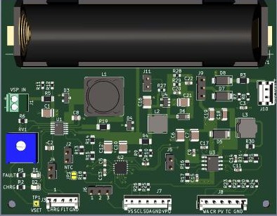
 Open Green Energy
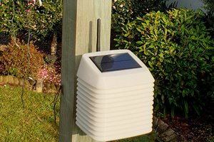
 hayden