I have been working on revision 2 of the LRMS boards. Component placement is completed and I will be routing
Transceiver and gas sensor boards.
- All board dimensions have been updated to 90mm x 70mm (LxW). This supports inexpensive 70mmx90mm prototyping boards.
- Connectors have been changed to 2x10 row connectors and aligned on 2.54mm spacing from board edges.
- Added a new board - LRMS Environmental Gas Sensor. This a design based on my original Rev 1 test board.
LRMS LoRa Transceiver R2
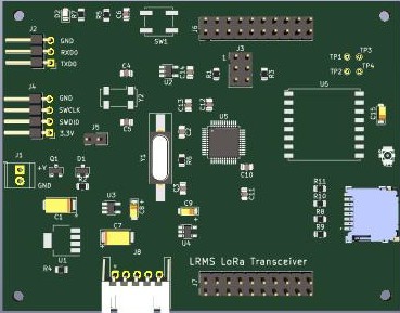
Revision 2 :
uSD card connector for data logging
JST connector for connection to LRMS MPPT Solar Power Module
- Reverse power polarity protection
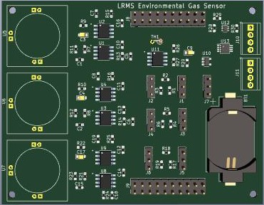
LRMS Environmental Gas Sensor
![]() Spec Sensors Electrochemical gas sensor array
Spec Sensors Electrochemical gas sensor array3.0V Lithium Cell or 3.0V LDO regulator - Ultra low power op-amps for
- I2C bus connector
- UART connector
 Spec Sensors Electrochemical gas sensor array
LRMS MPPT Solar Power Module
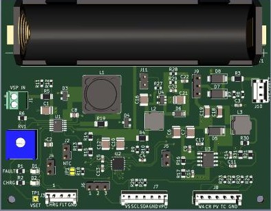
- J7 & J8 JST connectors changed to 5 pins. J7 is for I2C bus interface and J8 is for INA3221 status.
Discussions
Become a Hackaday.io Member
Create an account to leave a comment. Already have an account? Log In.