 ElectroBoy
There are many online converts are available to convert Mp3 files into Arduino compatible WAV files. These are the special audio files Arduino can recognize and store them as data. Our Arduino has 6 channel 10-bit ADC which can be used for this purpose. Inbuilt ADC is capable to convert any mp3/ audio files into 8-bit resolution with 16000 compatible frequencies. Same files can be converted using online converters available on internet. But this is the most physical method to record and store the audio.
Similar idea can also be used to make a spy bug to record audio and play them as wav. The audio quality is little bit disappointing but a very interesting project to make. I will give you a full project on that as soon as possible. And make a NANO size PCB for that project. JLCPCB is the most reliable PCB manufacturer and offering the best service in very cheap price, try JLCPCB now from here and get coupons of $54 on first sign-up.
WAV files:
Waveform Audio File Format is an audio file format standard, developed by IBM and Microsoft, for storing an audio bitstream on PCs. It is the main format used on Microsoft Windows systems for uncompressed audio. The usual bitstream encoding is the linear pulse-code modulation format.
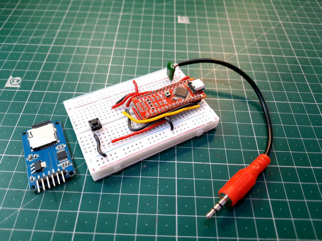
Components required:
1) Arduino NANO/UNO
2) MicroSD card module
3) MicroSD card
4) Aux port
5) Battery 9volt
6) Tactile button
7) Connecting wires
8) PCB designs from JLCPCB
Setting up microSD card:
Put the SD card in PC and categorized the file format as FAT32, then delete all the files from SD card. To format the whole volume in FAT32 go to disk management in PC and select partition as FAT32.
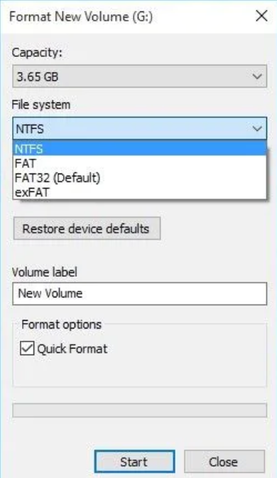
Hardware wizard will automatically do rest of the work itself. Every time when you start record the audio, SD card should be fully empty. It will not work if there are files of the same name.
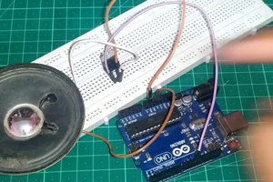
Circuit used:
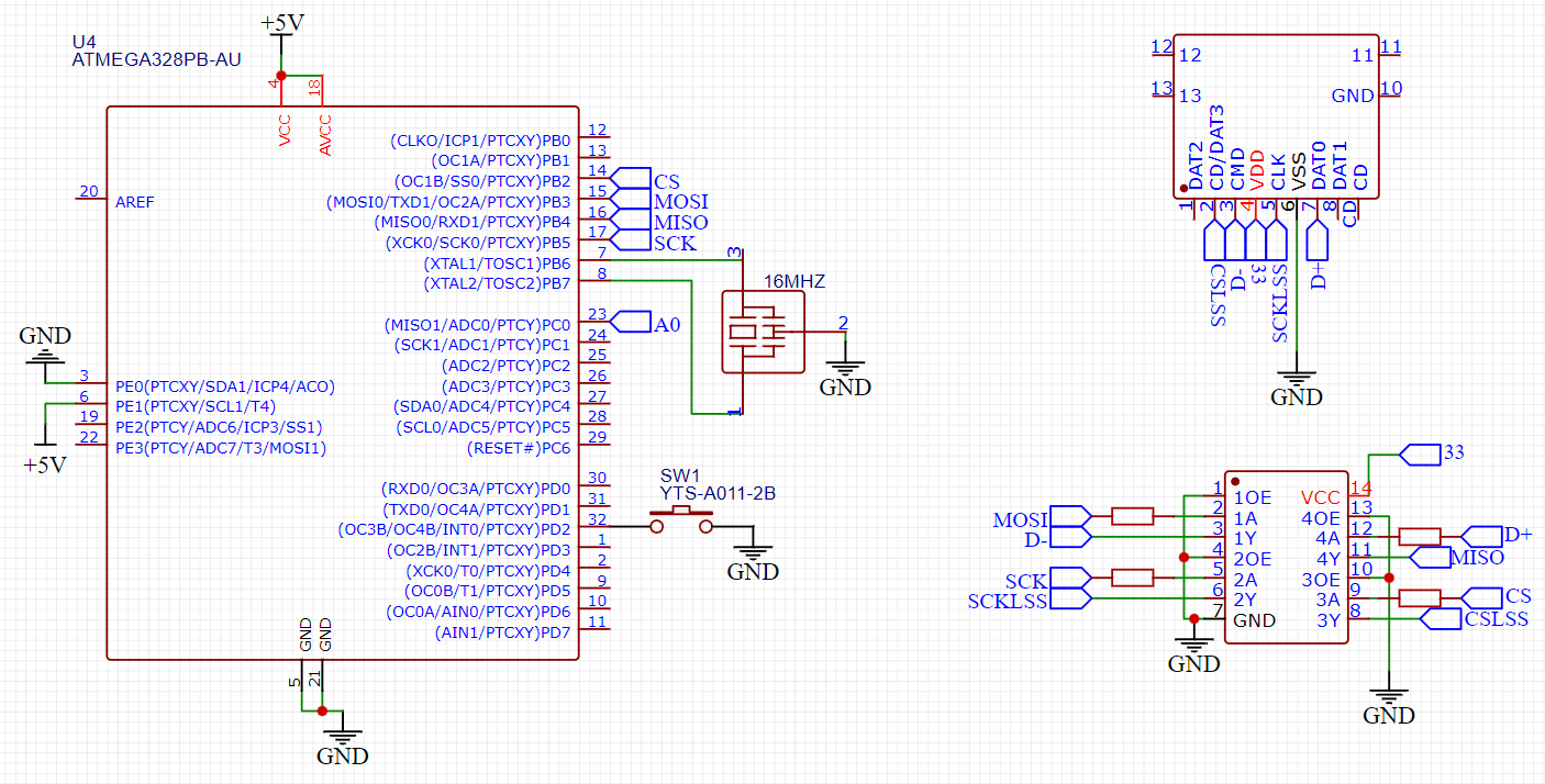
To pair the SD card module with Arduino SPI connections are used. SPI, MISO and MOSI are connected to digital pin 13, 12 and 11 respectively. Chip select is used to determine the working condition and if SD card is present inside module or not. So it is connected to digital pin 10 of Arduino to give a proper signal. A tactile button is connected to digital pin 2 which is used to stop the recording and start new file. A single trigger of tactile button is enough to do this job. 9-volt battery can be used to power whole the circuit.
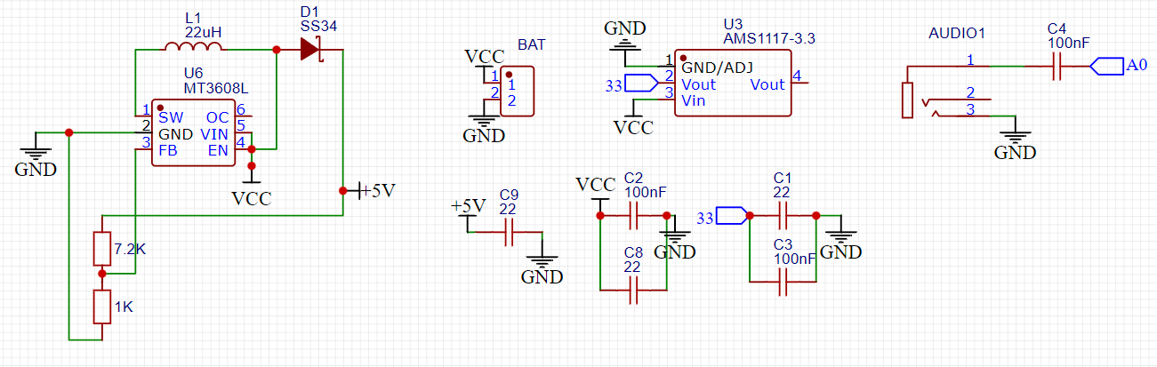
Analog pin is used as audio input, it can only work in mono channel. SO we can give any type of a preamplifier signal there to record. In our case an AUX cable is there to record the audio. A boost converter is also added here to provide +5volt to Arduino. Because using a 3.7 volt battery it is not possible to power both SD card and Arduino at same time.
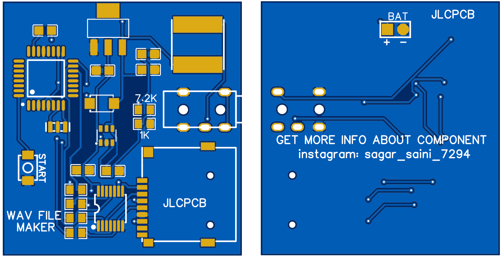
PCB files:
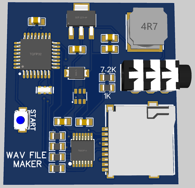
I convert the modified schematics into PCB files using EasyEDA and then place an order on JLCPCB. And if you want to order the same PCB as mine then download all the files from here. All the BOM and CPL files are also placed here which can be used to order SMT assembly from JLCPCB.
JLCPCB is the most reliable PCB manufacturer and offering the best service in very cheap price, try JLCPCB now from here and get coupons of $54 on first sign-up.
Arduino code:
#include <SD.h>
#include <SPI.h>
#include <TMRpcm.h>
#define SD_ChipSelectPin 10
TMRpcm audio;
int audiofile = 0;
unsigned long i = 0;
bool recmode = 0;

void setup() {
  pinMode(A0, INPUT);
  pinMode(6, OUTPUT);
  pinMode(2, INPUT_PULLUP);
  attachInterrupt(0, button, LOW);
  SD.begin(SD_ChipSelectPin);
  audio.CSPin = SD_ChipSelectPin;

}

void loop() {
}

void button() {
  while (i < 300000) {
    i++;
  }
  i = 0;
  if (recmode == 0) {
    recmode = 1;
    audiofile++;
    digitalWrite(6, HIGH);
    switch (audiofile) {
      case 1: audio.startRecording("1.wav", 16000, A0); break;
      case 2: audio.startRecording("2.wav", 16000, A0); break;
      case 3: audio.startRecording("3.wav", 16000, A0); break;
      case 4: audio.startRecording("4.wav", 16000, A0); break;
      case 5: audio.startRecording(...
Read more »
 UTSOURCE
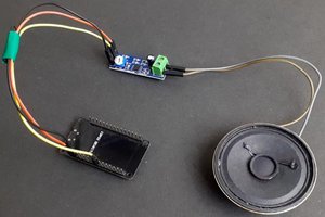
 electronicsworkshops
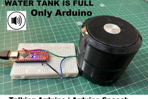
 Lithium ION
 Samuel Alexander