Texas Instruments has a great solution for this - the SN6501 Transformer Driver. Even better, Wurth has a complete family of transformers to go with the SN6501 with agency approvals. But thanks to the semiconductor supply chain melt-down you can't get it for at least a year.
With a low-end PIC micro-controller, a few discrete parts, and a tad more board space you can do the same thing and add control features like Enable.
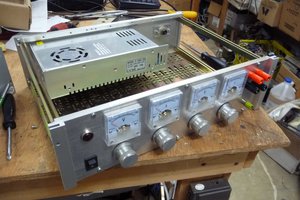
Here's the eval board. I always do something like this with a new idea or components no matter how comfortable I am. I've standardized on a micro-A/B USB jack for all of my PIC projects but you can substitute whatever works best for you.
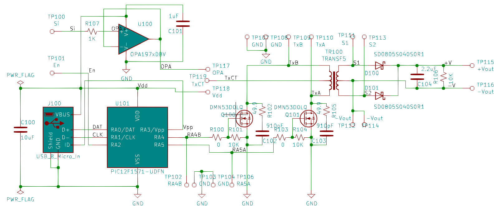
The PIC is configured as a push-pull driver with an enable pin. Gate resistors R100/103 are not needed and can be eliminated from an actual design. The Wurth transformer I used is #760390014 with a ratio of 1.3:1 turns. For a 5V input you'll get 5.4~6V depending on load. Add an LDO for a precise output. For 10+ volts the secondary could be configured as a voltage doubler.
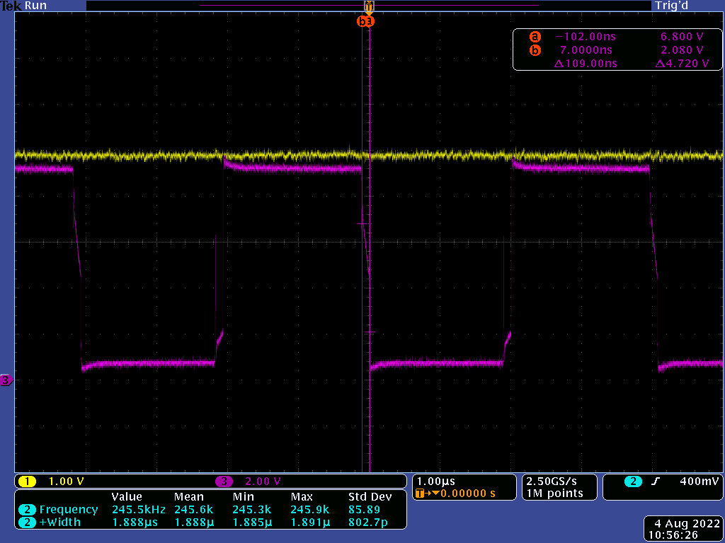
My main focus for the eval was dynamic performance - efficiency, regulation, and noise. Here's a trace with Vin=5V and a 200mA load. Channel 1 is the output and channel 3 is the switching waveform at TP110. Each side is on for ~ 2uS with a 62uS dead time to prevent shoot-thru.
Efficiency is a flat 77% above a 50mA load and the highest temperature rise was the switches at 12C with a 200mA load. This is basically a DC Transformer so very little filtering of the output is required - I only have 2.2uF. Idle current (no load) is 17mA with Vin=5V. With Enable LOW it drops to 2mA.
Interestingly, the TI data sheet does not indicate the need for snubbers (C/R102 & C103/R105) but I observed considerable ring without them. It may be due to the switching times being 10x faster than those of the Sn6501.
You'll notice the TI OPA197 op amp configured as a follower: this has nothing to do with testing the isolated bias supply per se. I included it to test the crazy idea of using this setup to convey voltage sense across the output isolation barrier for a power supply control loop. The traditional way to do this is with an opto-isolator but I don't like them (they also create dissipation issues in high-voltage secondaries). I have been playing with Analog Devices ADuM3190 isolation amplifier but was curious if the transformer (without output capacitance) would provide better bandwidth.
The answer is maybe but probably not worth it because the dynamic performance won't be better than the ADuM3190, require more board space, cost, discrete components, development time, etc..
If found that the OPA197 has no problem driving the transformer with only a small bias load of a few mA. The main problem is the switching noise created by the dead band for each leg. It comes out to about 100nS but is of significant amplitude - about 1V p-p. Even though this is way above the bandwidth of control loops I worry that it would create stability or jitter issues. Adding capacitance helps at the expense of bandwidth: I noted an 11 degree phase shift @ 30kHz. And the noise is still a concern.
 Rue Mohr
 Paul Andrews
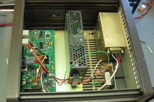
 Quinn
Quinn
 helge
helge