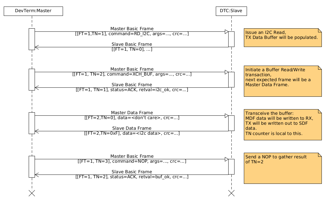
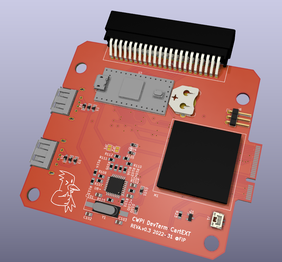
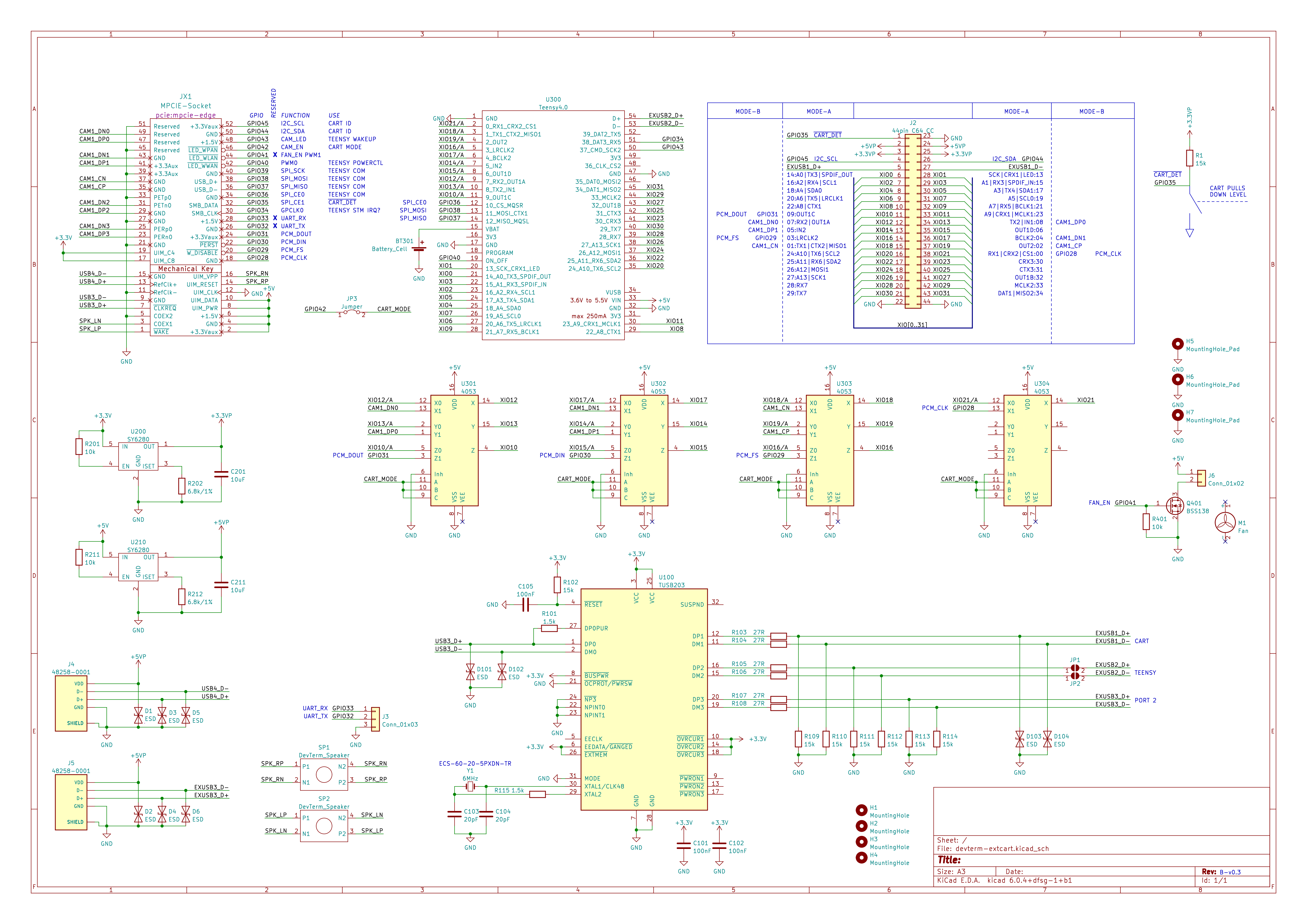
• Soldering all the Teensy pins

    flip09/16/2022 at 17:23 0 comments

    In this post, we explore the process of soldering all of the Teensy4.0s' pins. Yes, all of them, even the SD card ones.

    First, the setup: I got a Weller WE1010, with a brand new 0.4mm conical tip heated up to the maximum of 450°C. I chose a very high heat for two reasons: First, the thermal transfer is very much bottlenecked by the fine tip, and secondly I'll be burning off the coating on the enameled copper wire with the iron. The wire diameter chosen was 0.4mm, which might be the first mistake but worked barely.

    First, the most problematic SD port wires were cut with length to spare, inserted and taped down on the chip side. My use of ordinary tape did work out in the end, but Kapton is obviously the way to go there if you got it.

    Tapedown of the wires, using normal tape. Not recommended.
    Tapedown of the wires, using normal tape. Not recommended.

    Then, the wires were soldered on the other end. The trick is to use too much solder with plenty of flux, and wipe the excess using a desoldering braid.

    Once those were fixed in place, I then started by soldering the USB host pins, those were relatively easy. Now the Teensy4.0 was fixed in place which turned out to be of help. Then, I tackled the SD card pads. First, cutting the wires to length using my best judgement, it turned out to be a bit too long. After that, the wires were soldered on. I then proceeded to bend the wires using a 3mm round stock in hopes that this eases the strain later when bending the wires down.

    Bending the wires with the piece of roundstock.
    Bending the wires with the piece of roundstock.

    Now, the easier pads on the left remained. I needed to cut those wires extra long so that they reach the designated holes while in this position. The excess will be cut when bending the board into position. After that, the pin headers were added.

    All bottom pads are finished and the pinheaders are added. Now to flip the board.
    All bottom pads are finished and the pinheaders are added. Now to flip the board.

    Then came the nerve-wrecking part, bending it all into place. With a slow and steady pace, the Teensy was brought into position. I didn't felt anything snap off which was a good sign.

    Now the part where it all fails: The wiring takes up too much vertical space! The thinner 2mm spaced headers were not seating flush. Disappointing to say the least. The choice of 0.4mm wire was bad after all, not to mention the necessity to solder these pins in the first place. After checking the fit within the DevTerm, it stands too tall and the case still flexes. All in all, the operation was a failure. But I'm hopeful that all the connections held up in the process. Testing later will either confirm or deny that. What is certain tough that this process is way too hard. I wouldn't want anyone to spend hours deadbugging a Teensy and then let them pray nothing snaps when flipping it. 

    The full board


    What to do next? There are two options: Redesign the board into a whole new revision, or print a backshell for the DevTerm that has the clearance for the Teensy. The latter may be okay temporarily, but no way I'm calling this done with that design flaw.

    I already have a few ideas for a new board. Most likely solution is to use the Teensy4.1, which would be challenging due to its size but is the most doable option. Then there's the crazy option: cutting out the space within the Teensy to allow access to the bottom pads, but again, not the way to go as the SD card pads are still not easy to solder. Then, there's the option of just using the chip directly and letting a fabricator solder in all the parts. Out of my league to say the least.

    Finally, some good news regarding software: The Linux driver is coming together: I2C works fine, not fast but acceptable. Support for all the UARTs is in the works currently and SPI will be added later.

  • This project is sponsored by PCBWay

    flip09/16/2022 at 16:40 1 comment

    PCBWay reached out to sponsor this project by providing the next round of prototypes.

    The newly arrived PCB, sponsored by PCBWay
    The newly arrived PCB, logo wasn't required to be put on but I did it anyway

    A big shoutout to Liam, the whole process was uncomplicated and fast.

    Speaking of fast, the PCBs arrived within ten days, and production finished in 5 days without counting the Moon Festival.

    I even received more than ordered, a total of 10. The color is a bit darker then the previous revision by JLCPCB, but it's very subtle.

    The edge routing is clean and the specified thickness is spot on and fits the PCI-E slot as intended.

    From a quality standpoint, I cannot complain. Even the silkscreen torture test came in legible. Each letter is 0.5x0.5mm², following is a microscope shot.

    The classic text to put under a chip, perfectly readable especially at a distance.

    The solder mask itself is without flaw: it is crisp and pads line up perfectly. This prototype went all out with the surface finish by using immersion gold, which looks nice and is guaranteed to last long.

    Microscope shot of a tighter pitched component
    Microscope shot of a tighter pitched component

    All in all, I'm very happy about the quality of the PCBs and how fast they arrived. PCBWay is definitely recommended.

  • A Tour through the intial Software

    flip09/09/2022 at 20:57 0 comments

    Lua Interpreter

    As stated previously, the firmware features a Lua 5.4 interpreter.
    The configuration has been hammered down more or less to be able to run under Zephyr and the Teensy4.0.
    Here's the key things to make it happen:

    • #define LUA_32BITS 1 in luaconf.h is an obvious one
    • Zephyr doesn't ship with whole POSIX compatibility, so a few functions were copied from civetweb
    • The "KB" macro in lvm.c had to be redefined to "_KB" so that it doesn't clash with the existing Zephyr one

    There are some things that I forgot to document, but if you happen to want to embed Lua into the Teensy4.0 in PIO's Zephyr than just drop me a message and I'll send over the code.
    But Lua is only as exciting as the functions it comes with, here's a list of them:

    • bload: Load Lua bytecode
    • run: Run loaded Lua bytecode
    • poke: Poke around at any address, supports 8, 16 and 32 bit words
    • peek: Peek around at any address, complimentary to poke
    • rshift/lshift: Do a right/left bitshift on a value
    • band/bor/bneg: Bitwise and/or and negation
    • memused: Print current amount of memory used for Lua
    • memfree: Print remaining memory available to Lua
    • printlog: Prints the Zephyr log
    • pp: It's the pretty print function
    • hex: Convert a numeric to a hexadecimal string
    • xio_set/xio_get: Set and get an IO on the cartridge
    • xio_peek/xio_poke: Set and get all 32 available IOs at once
    • Currently, only I2C peripheral function exist, but this will be extended to SPI, UART, CAN and eventually ADCs

    Bytecode currently is compiled using an emulator on a developer machine, which can later be incorporated into a cartridges I2C EEPROM to be loaded on plugging in.

    SPI Protocol

    Meanwhile, the SPI communication between the DevTerm and the DTC Module is coming along well. Slave configuration was really easy by using the MCUXpresso library. As with all peripherals that are used during runtime in Zephyr on the Teensy4.0, the pinmux has to be adjusted before usage. On the topic of pinmux, I found out that on my version, the configuration for LPSPI3 seems incorrect. It is easily fixable tough.

    The SPI protocol utilized is simple, featuring a start byte and end CRC8 for both validation of the frame and detection of the frame end. There are two types of frames utilized: Basic and Data.

    Basic Frames are fixed width and is the go-to for exchanging. Basic frames contain a command and argument from the master, and a status code and return value from the slave. Then, there's Data Frames which are utilized currently by one command: the buffer exchange. By issuing a buffer exchange command, a local all-purpose buffer can be read and written to. This all purpose data buffer is where the the data for peripheral commands such as for SPI and I2C is. A basic frame beforehand will contain the neccesary length information for a following data frame.

    Types of frames
    The types of frames used. The magic byte at the start consists of the frame type (FT, basic or data) and a transaction number (TN) which increments with basic commands.

    An example exchage is illustrated in the following diagram, outlining the neccesary transactions for one I2C read of up to 128 bytes.

    Big thanks to @yatli for all the valuable input on the ClockworkPi forums regarding the protocol among other things.

    Linux Driver

    Currently, a cheap python script is used to test the protocol during development, but a fully fledged Linux driver is in the works that exposes the IO as GPIO, as well as the I2C buses. I currently have no idea to implement an SPI or CAN driver on Linux, but it is definitely on the todo-list.
    A wiring-pi like Python library would be nice to have on top, but I'm unsure if it will be necessary at all.

  • First Prototyes I made, Last Mistakes I'll ever make again

    flip09/04/2022 at 20:55 0 comments

    First revision of the board came in some weeks ago. First mistake was with populating the Teensy4.0. As almost all available pins are used in the design, including the SD-card interface ones, great care has to be put into soldering it down. I chose a rather rigid wire for these SD-card pads, and behold, it ripped the traces right off. Not all is lost tough, plenty of initial prototyping can be done without those. Second mistake was more severe, I left the SCLK line to the DevTerm unconnected in the schematic. A simple bodge wire to the pad on the PCI-E connector was no problem, altough not recommended since it does leave a dent in the recepting connectors' plastic.

    SCLK Bodge
    The SCLK bodge wire in full view.

    From a mechanical standpoint, the design so far is solid. The USB ports, mounting holes, cartridge connector, everything lines up as it should, with the exception of the Teensy which is soldered with standard 2.54mm headers and stands off a bit too far. For the second prototype, a thinner header row is already ordered which should fit. The DevTerm barely can be reassembled with a little flex in the cover. Besides that, plugging in a cartridge is satisfying after many hours spent in FreeCAD.

    Back view
    Back view of the DevTerm with the passthrough cartridge inserted.

    The firmware is based on PlatformIO's Zephyr environment for the Teensy4.0. I recommend using Zephyrs' drivers only after you checked the sources. I tried a slave configuration for the SPI communicating with the DevTerm, with no errors. This was a fatal mistake, as the driver does accept a slave configuration, but instead configures the SPI as a master. Now I had two masters pushing and pulling on the same lines. I could have known something was up due to the whack scope measurements, but I chalked it up to bad routing distorting the signals. The result is that the DevTerms' CS0.0 seems fried, it doesn't pull down as it used to. I moved forward using a Raspberry Pi 3, which I should have done in the first place to prevent this setback. Lesson learned is that you don't use your expensive unit to test. One interesting thing to note is that the firmware embeds Lua, which should allow easy download of cartridge specific functionality in firmware via Lua bytecode. Right now, bytecode can be loaded with the `bload('-',1)` statement via the USB ACM, later it should be possible to upload and run bytecode via SPI. The plan here is to use the I2C EEPROM in a cartrige to store said bytecode, which can be used to initialize the Teensys' peripherals but there's potential for more. This depends on a more clever implementation of the communication protocol used: Right now it's just a simple command word with an argument resulting in a response at the next transaction, with a 32-bit buffer in each transaction containing additional information. I tried implementing a protocol with varying transaction sizes to be more efficient, but with no success so far.

    Latest thing I tried was populating the USB hub. Initially, it looked dire: No oscillation of the quartz, and dmesg reporting an ERRNO -32 for the device. Sleeping over it, I found the culprits: bad choice of TVS diodes shorting out various lines and R115.
    Now, this series resistor is recommended by TI to prevent large currents at the crystal, and usually the reason why a design around the TUSB2036 doesn't work. Either the resistor wasn't soldered on correctly, or this did prevent the chip working.
    Anyhow, by bridging this resistor, the hub enumerates and works a charm.

    USB hub
    The populated USB hub portion, sans TVS diodes


    For the next round of boards, the newest revision fixes the missing SCLK line and adds a few pads to solder the Teensy's main USB to the internal hub. Alternatively, the Teensys' host USB pins can be selected for this USB downstream line via jumpers.
    Theoretically, one could use the MCUXpresso library directly in PlatformIO and configure USB2 as a device, but until then I'll connect the Teensy via a chopped Micro-USB cable on USB1.

  • Initial Status Quo

    flip08/07/2022 at 08:38 0 comments

    Currently, the schematic and board layouts are done.
    Boards are already ordered and will arrive in a few days time.

    The mechanical design of the cartridge is still a WIP, but should be able to fit the expansion port. As the C64 edge connector used is not keyed, notches on the side prevent accidentally plugging it the wrong way.

    Currently, I've made two cartridges to go with it: an Raspberry Pi compatible pinout, and a passthrough.
    The RPi interface cart can handle all but SPI1, but features all plethora of other options with the Teensy.