 StephanStrassleRojas
The purpose of this post is to give a quick introduction to the communication protocol that Märklin utilizes to control all their trains and accessories. Most of this information was obtained from old web pages that other Märklin DIY enthusiasts created. In the future, I plan to do a more thorough review and will include some oscilloscope screenshots of it in action.
Marklin has utilized different protocols through the years; the one with the most publicly available information and oldest has been Märklin Digital/New Märklin Digital. This protocol is what I will be designing my controller to work off of. This will hopefully help reduce the complexity of the controller, and because new control units (mfx) are backward compatible also provide the widest usability.
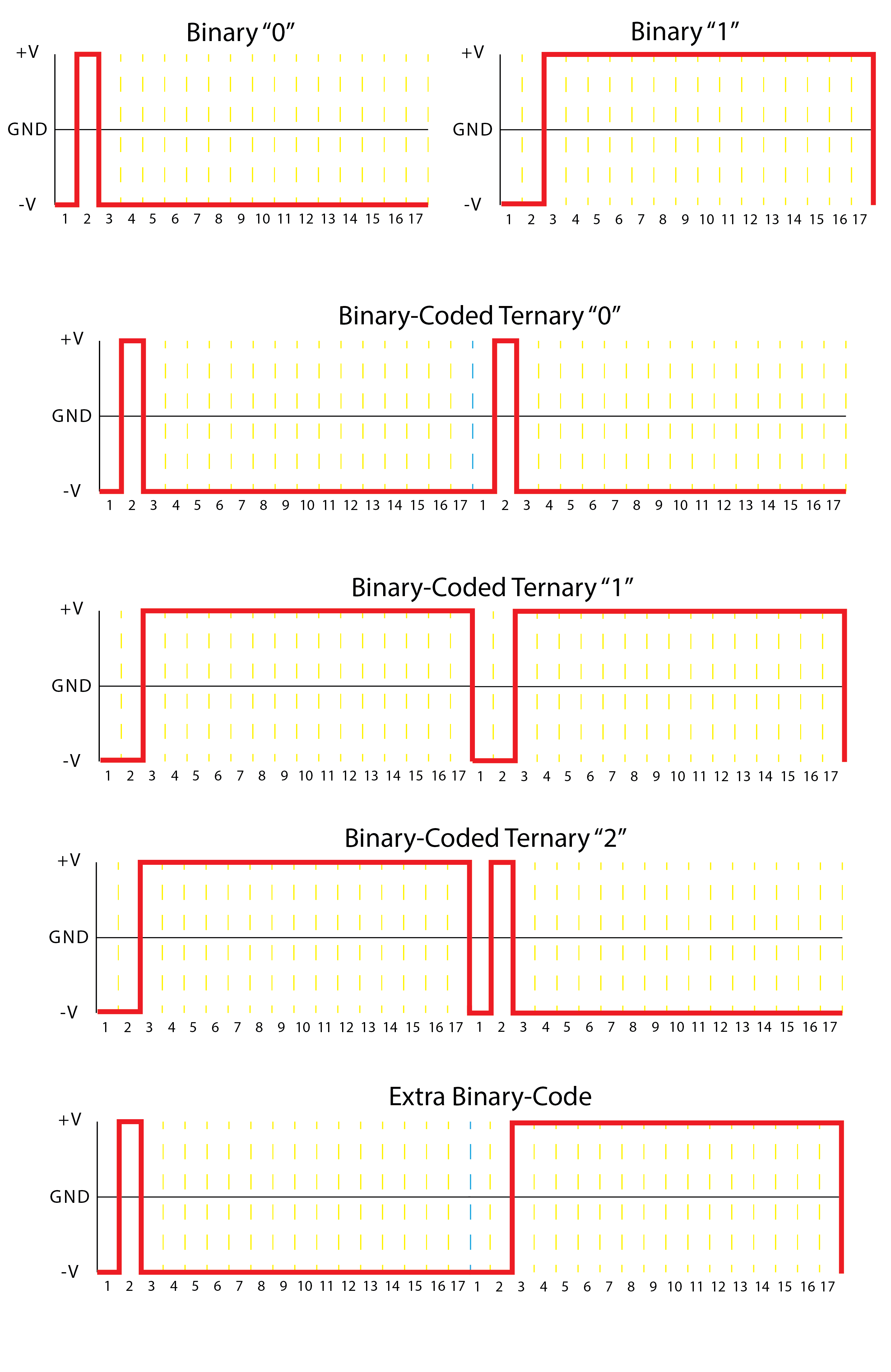
To begin online, you will often find that Märklin Digital is often referred to as Märklin-Motorola (MM). This is because the protocol was initially designed to work with a Motorola decoder (MC145027) which works with trinary data or more specifically binary-coded ternary. This means that two bits are used to represent three values, 0b00 -> 1, 0b11 -> 2, and 0b10 -> Open. This results in binary 0b11 being left unused. Märklin updated the protocol a few years after its inception to also utilize the 0b11 value, this is where the 'New' in New Märklin Digital comes from.
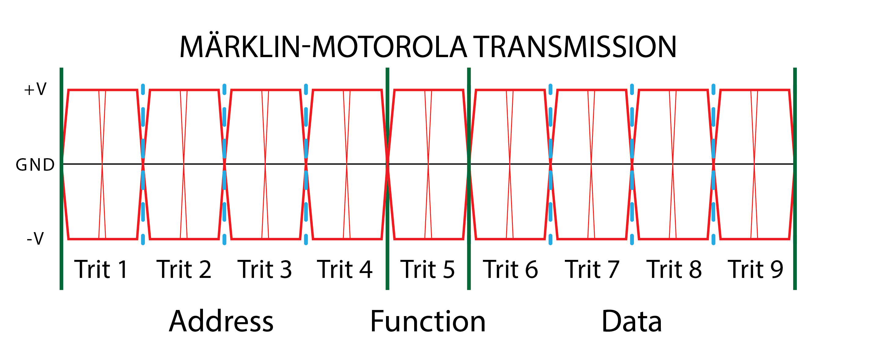
In Märklin Digital, a bit always starts and ends at its low voltage level (-15V). The duration of time in the high voltage level determines the bit value. A pulse that is high for 1/17th of bit time is considered binary 0 while a pulse that is high for 15/17th of bit time is considered binary 1. The first 1/17th of bit time has the signal at its low voltage level for both values. Binary 1 extends the low voltage dwell time in the beginning resulting in a low voltage state lasting for 2/17th of bit time. Two bits sent in series results in a trit. Nine trits make a message and each message is repeated twice in series with a low voltage dwell time in between.
Each message is composed of 3 components, address, function, and data. The first 4 trits define the controller's address, which this message is intended for. The 5th trit establishes the function of the message and trit 6-9 contains the actual data of the message (train speed, etc.)
Discussions
Become a Hackaday.io Member
Create an account to leave a comment. Already have an account? Log In.