 StephanStrassleRojas
Rectifier Block:
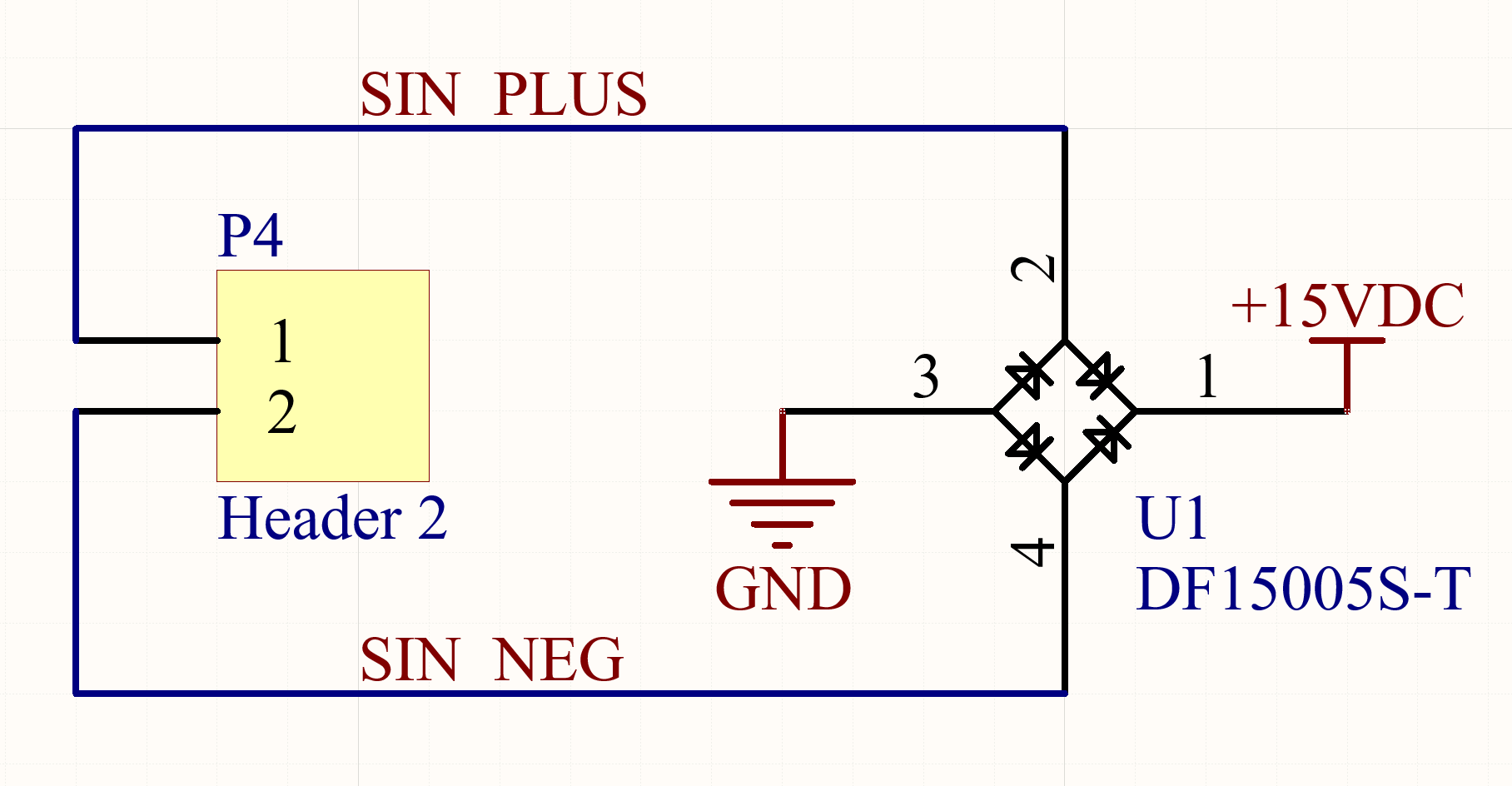
A full bridge rectifier is used to rectify the ±15V digital signal used by the Märklin Motorola protocol resulting in a steady DC output. The DF15005S-T was chosen as it is a full bridge rectifier incorporated in an SMD package that simplified board assembly. If the digital input signal is ±15V, the output DC voltage will be less than 15V due to the diode's voltage drop. Additionally, care must be taken when probing this circuit; the GND used on the controller may differ from that found on the Märklin Motorola driver, depending on its implementation. This means incorrect grounding of oscilloscope probes can result in a short between grounds with different potentials. A way around this issue is to use an isolated oscilloscope probe on the Märklin Motorola driver and standard probes on the controller or vis versa.
Power Conditioning Block:
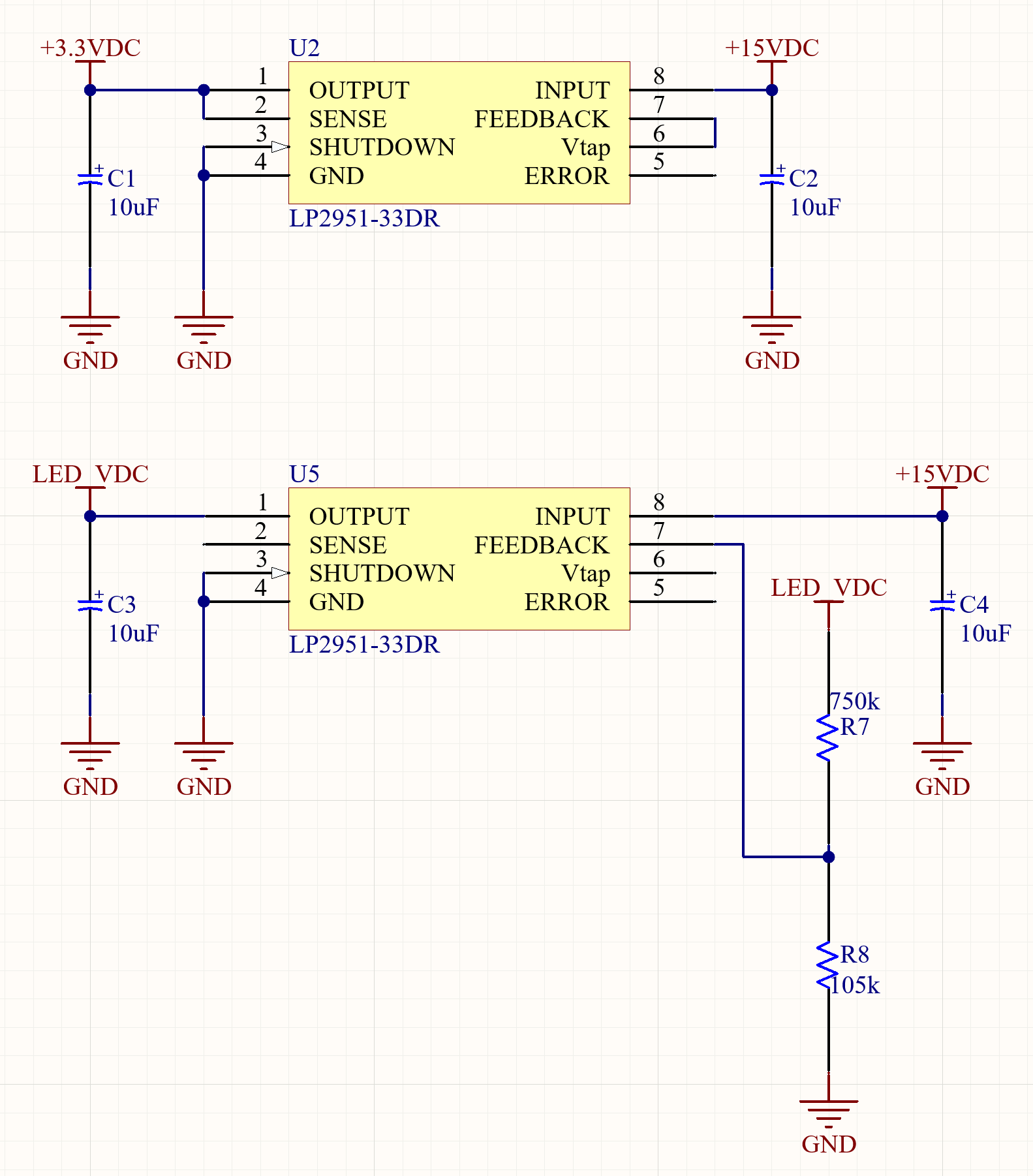
Three voltage levels are used on the control board design, ~15V to drive the solenoid, 10V for LED signaling, and 3.3V to power the MCU. As moderate variation in voltage does not affect the solenoid functionality, the solenoid drive voltage is directly tapped from the rectifier's output requiring no additional power conditioning components. On the other hand, the MCU requires a regulated 3.3V source to operate reliably, so a linear regulator is used to provide that. The LP2951-33DR was the LDO of choice as it came in an easy to solder package, could handle the required power dissipation needs, and could function as either a fix or adjustable output LDO. For the case of the MCU, the LDO was used in its fixed output configuration. A duplicate of the same LDO IC provided the 10V source for the signal LEDs. This was achieved by using the LDO in its adjustable output mode, with the voltage being set by R7 and R8. While LEDs are not as sensitive to voltage variations as MCUs are, I wanted these control boards to be able to handle a ±4V tolerance on the protocol's signal amplitude. Using an LDO to regulate the LEDs source enabled me to meet these criteria.
Signal conditioning Block:
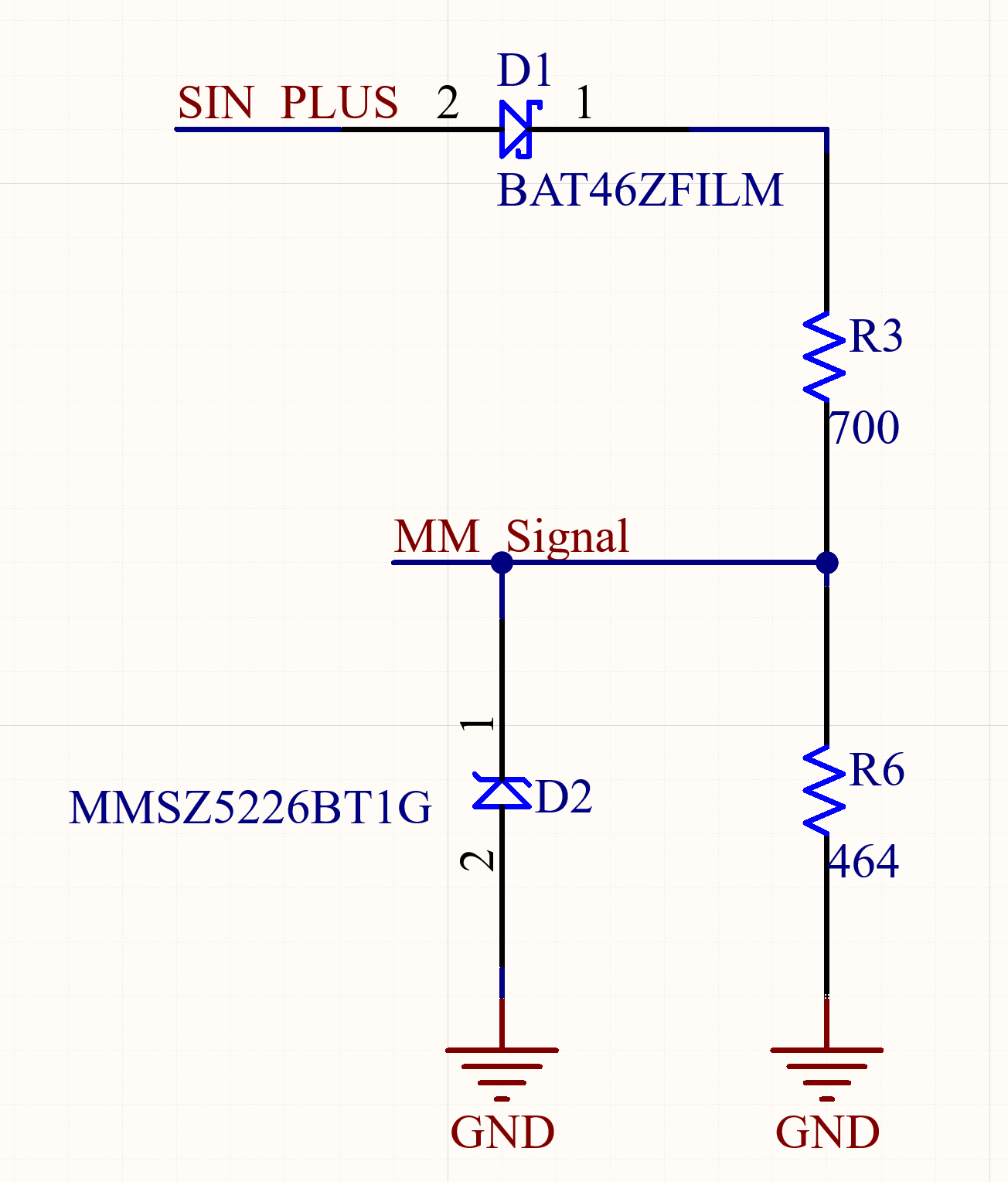
For the MCU to determine if a binary 1 or 0 is being transmitted on the protocol bus, it is necessary to sample the ±15V Märklin Motorola signal. However, the MCU's GPIO can't handle negative voltages or signals above the voltage powering the MCU, so conditioning needs to occur to generate a GPIO-friendly signal. The diode D1 stops any negative voltage from reaching the GPIO, and R8 pulls the line down to GND in those scenarios. The Zener diode D2 is used to clamp the GPIO line to 3.3V when the SIN_PLUS signal is above 10V. This circuit results in a signal (MM_Signal) that is 0V when SIN_PLUS is -15V and 3.3V when SIN_PLUS is +15V thus making it GPIO friendly. R3 was also added to act as a current limiting resistor for D2.
Discussions
Become a Hackaday.io Member
Create an account to leave a comment. Already have an account? Log In.
It seams that due to internal protection circuits, you can connect the data signal over a 22k resistor to most microcontrollers.
Are you sure? yes | no