deʃhipu
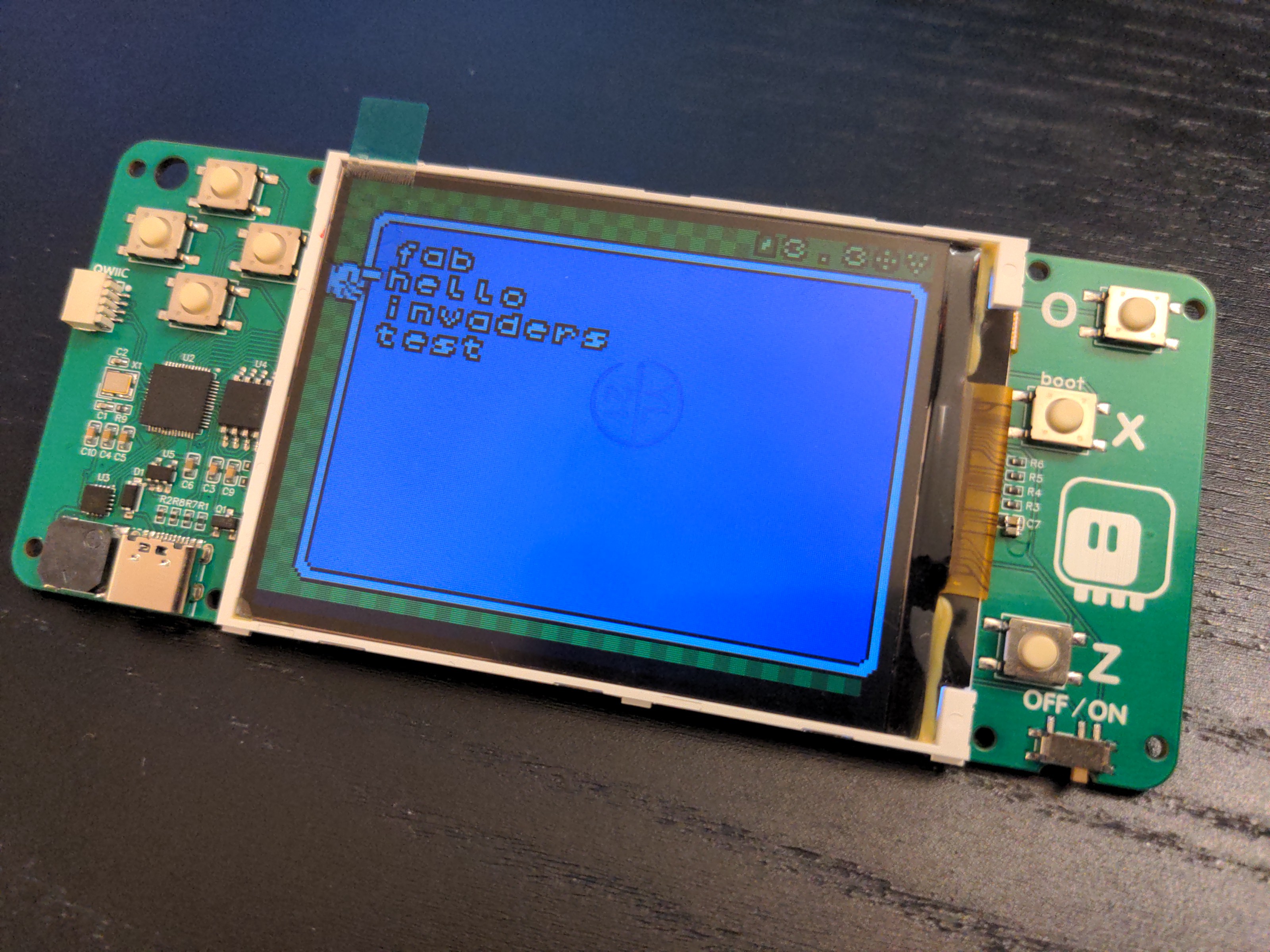
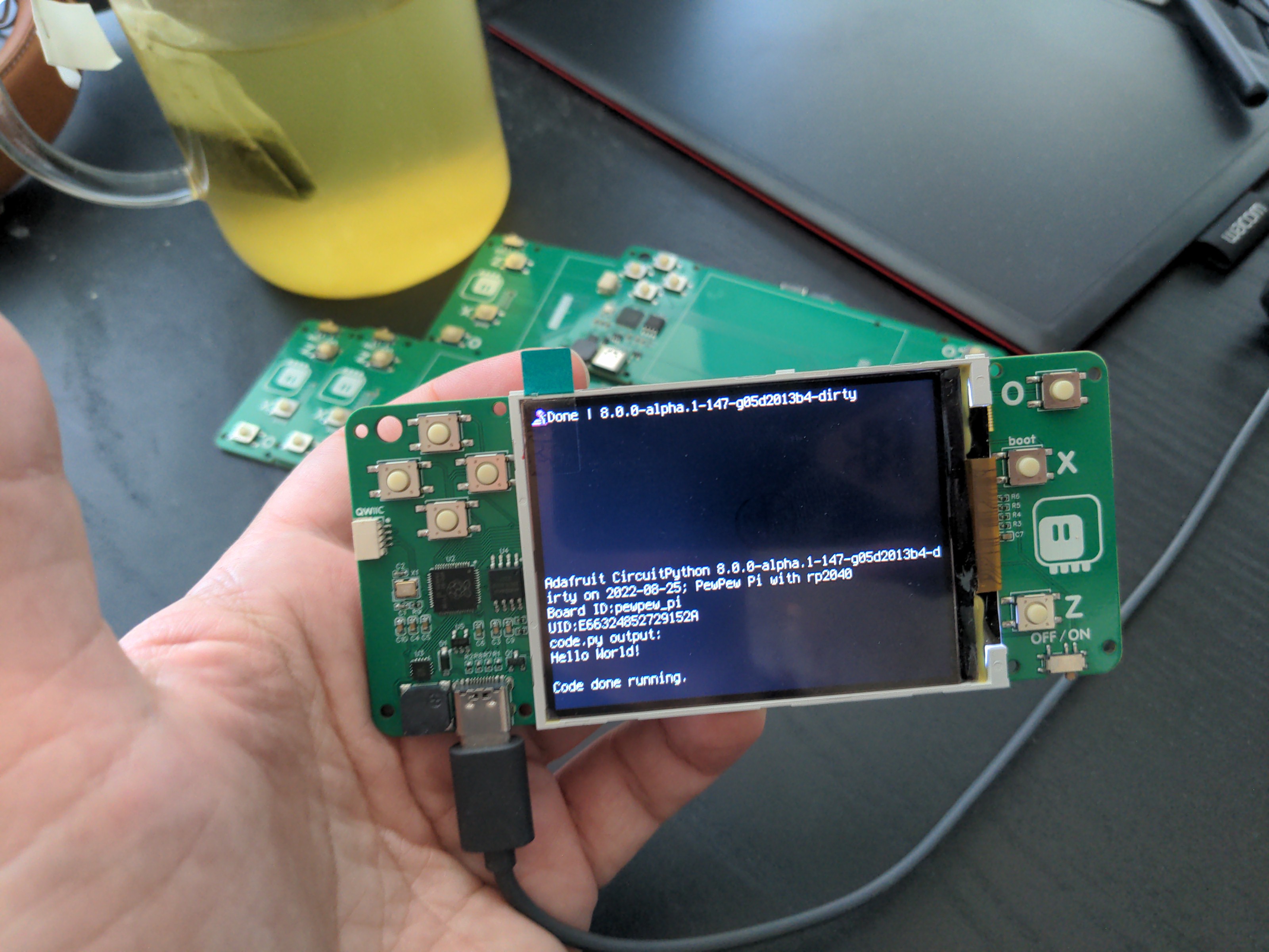
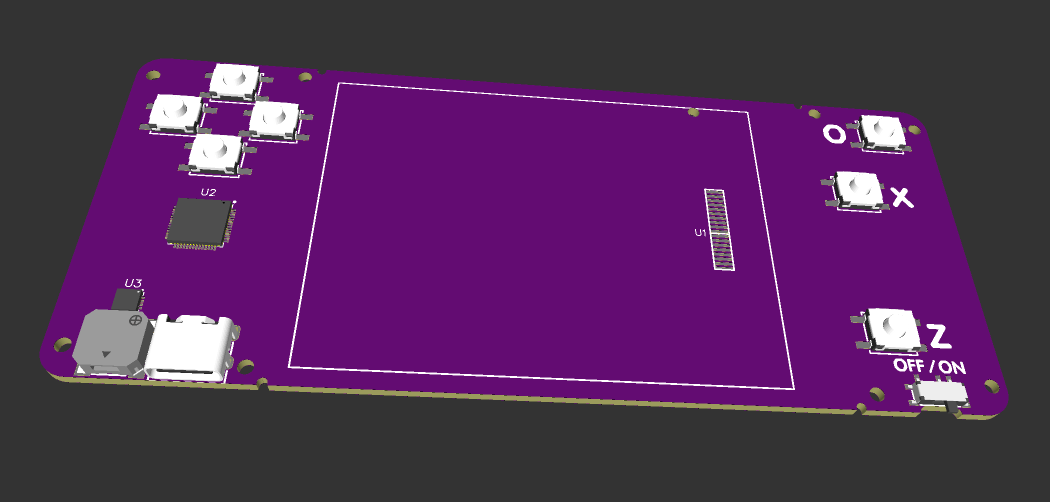
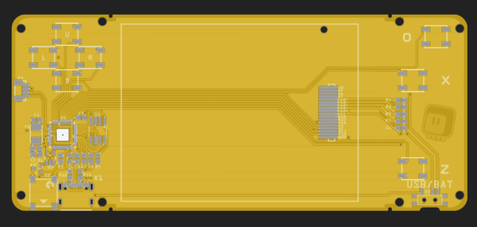
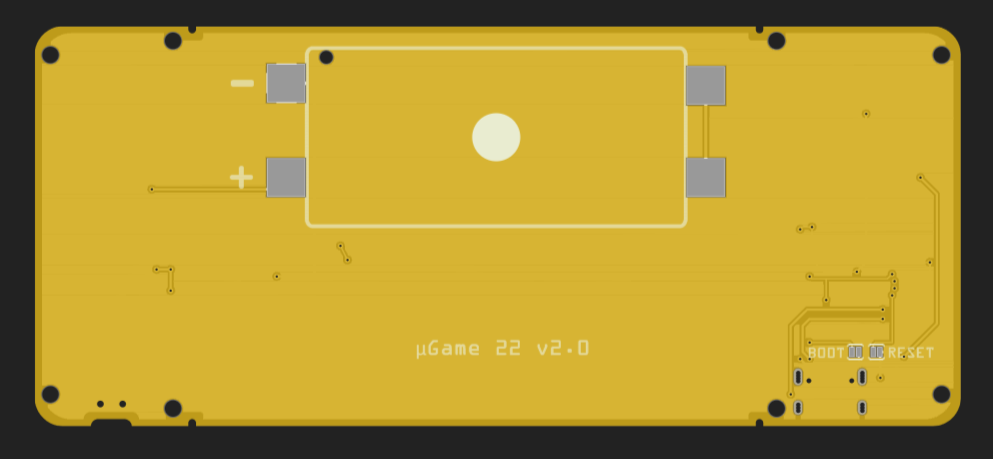
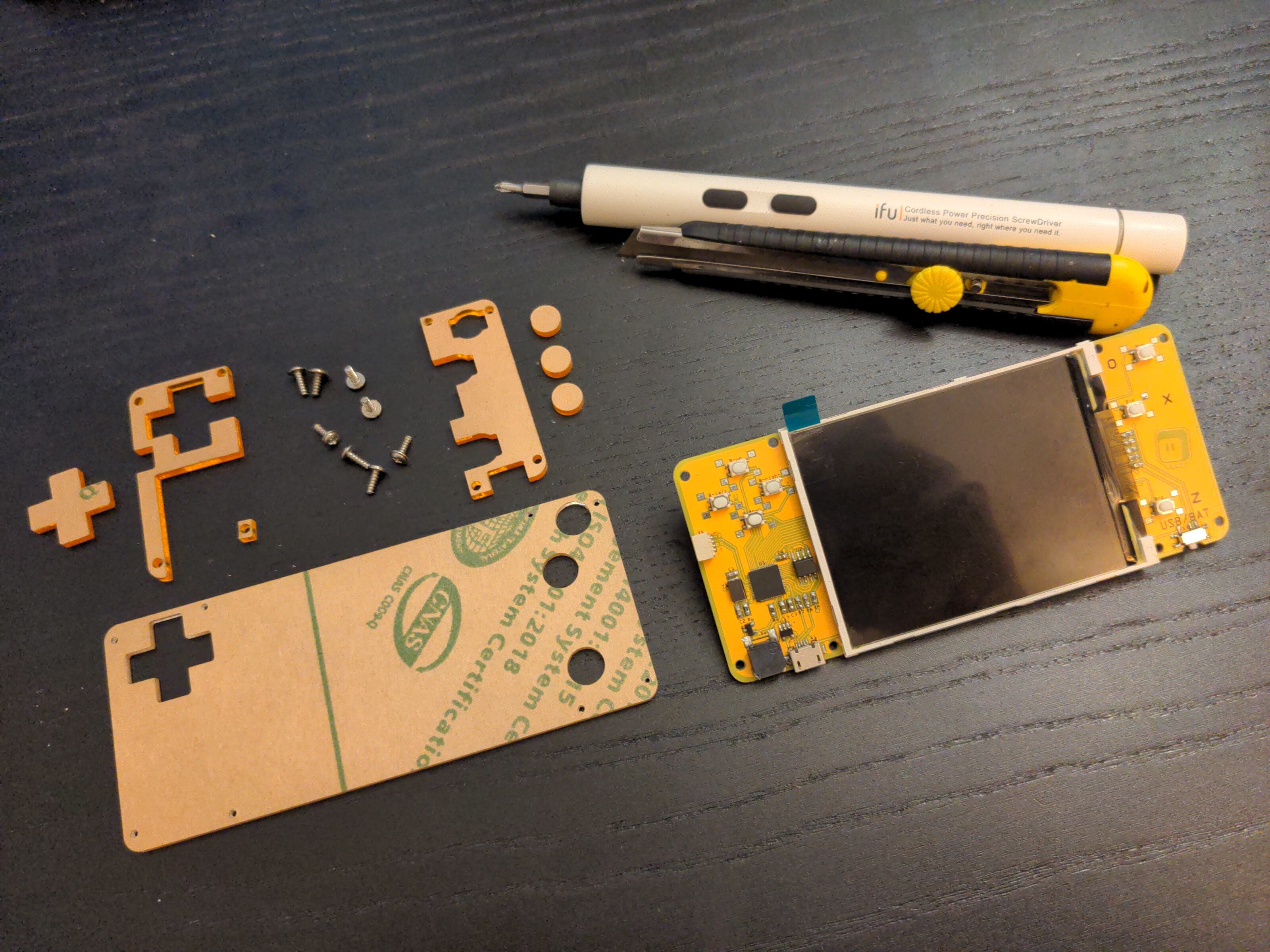
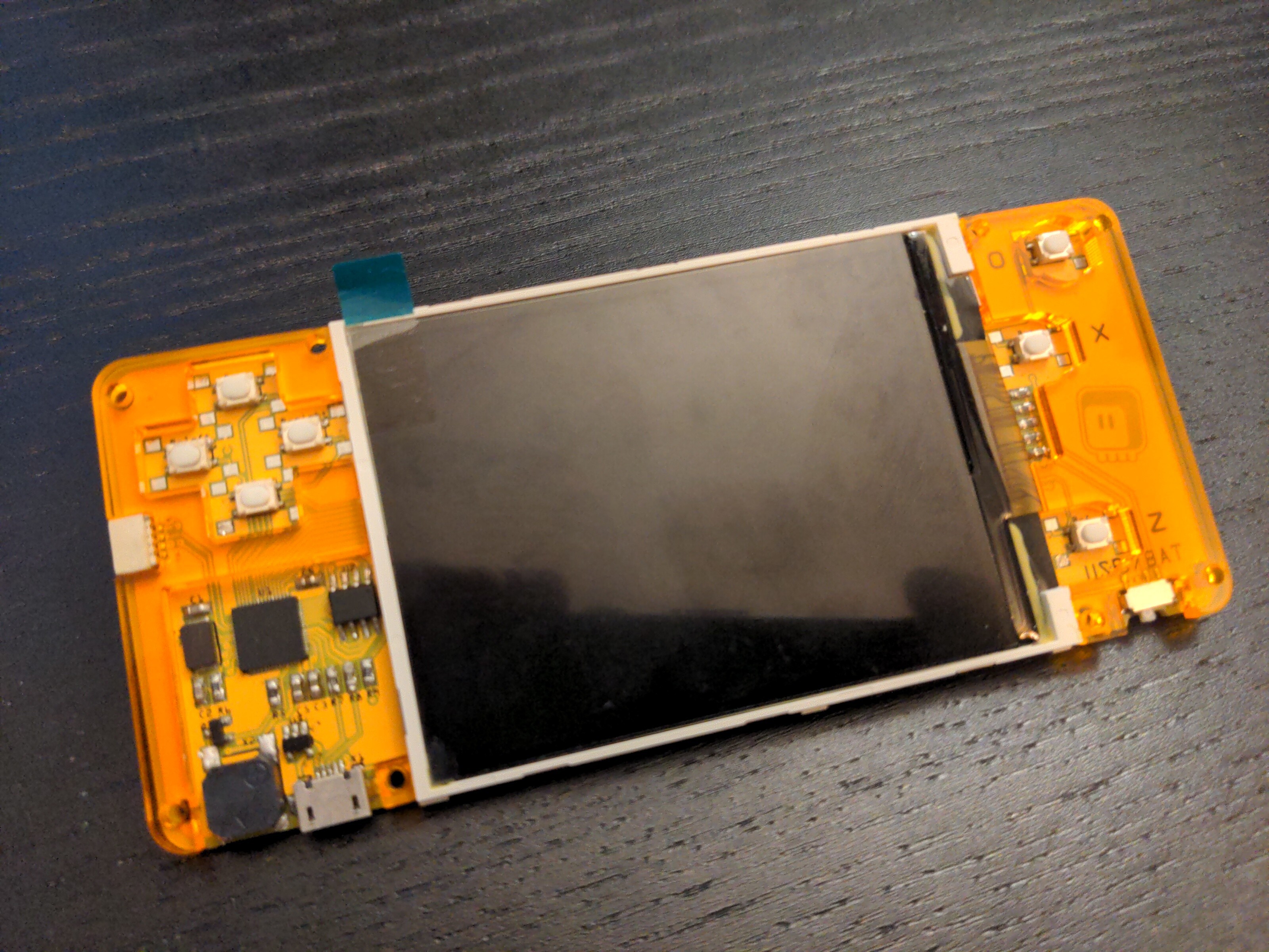
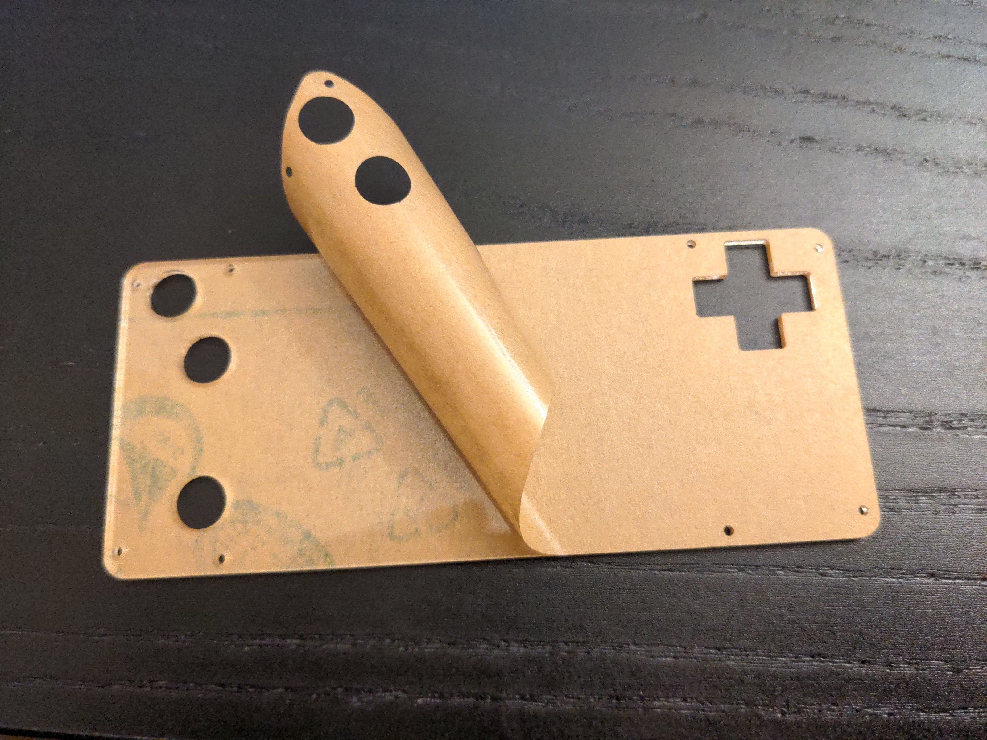
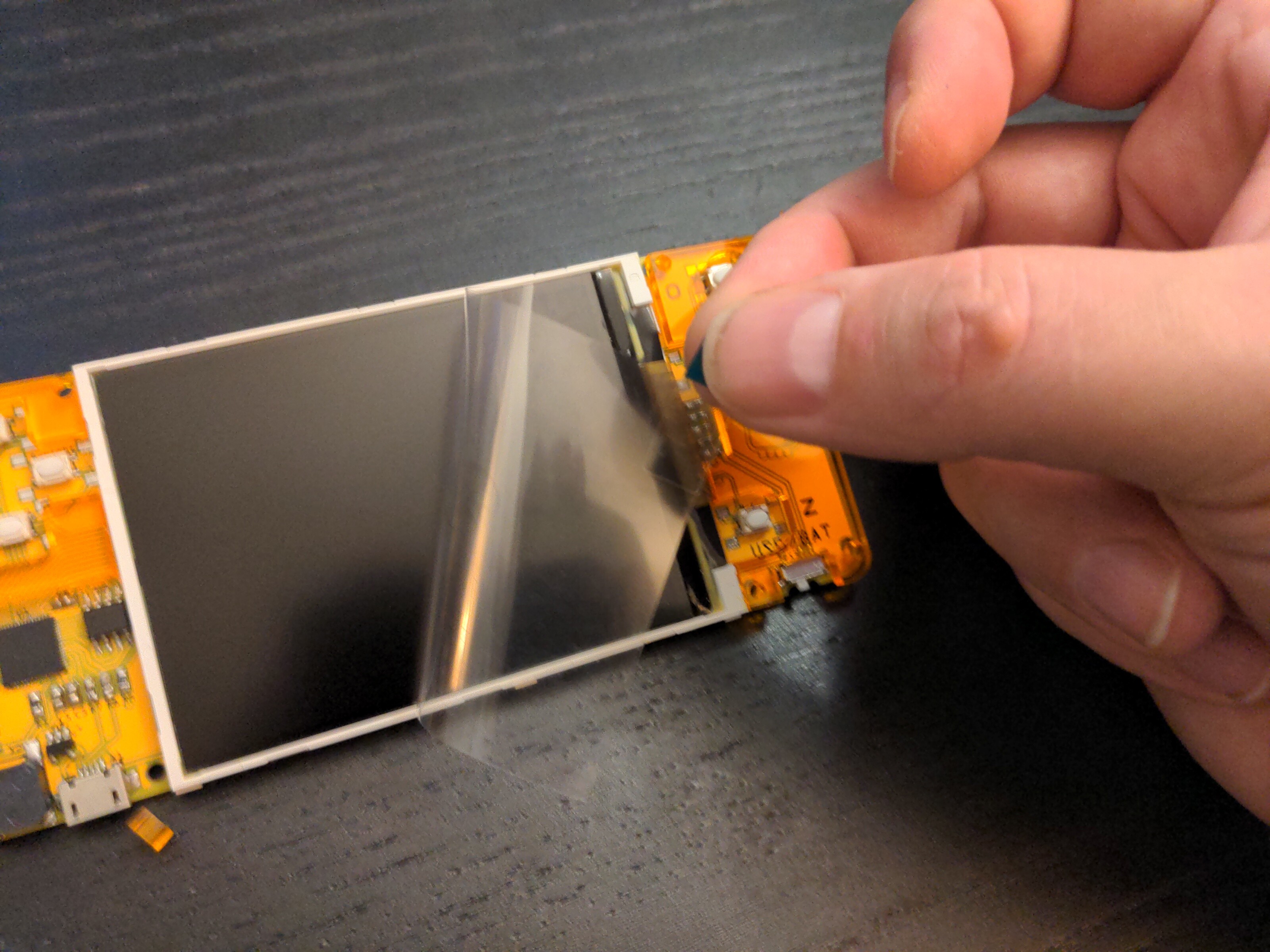
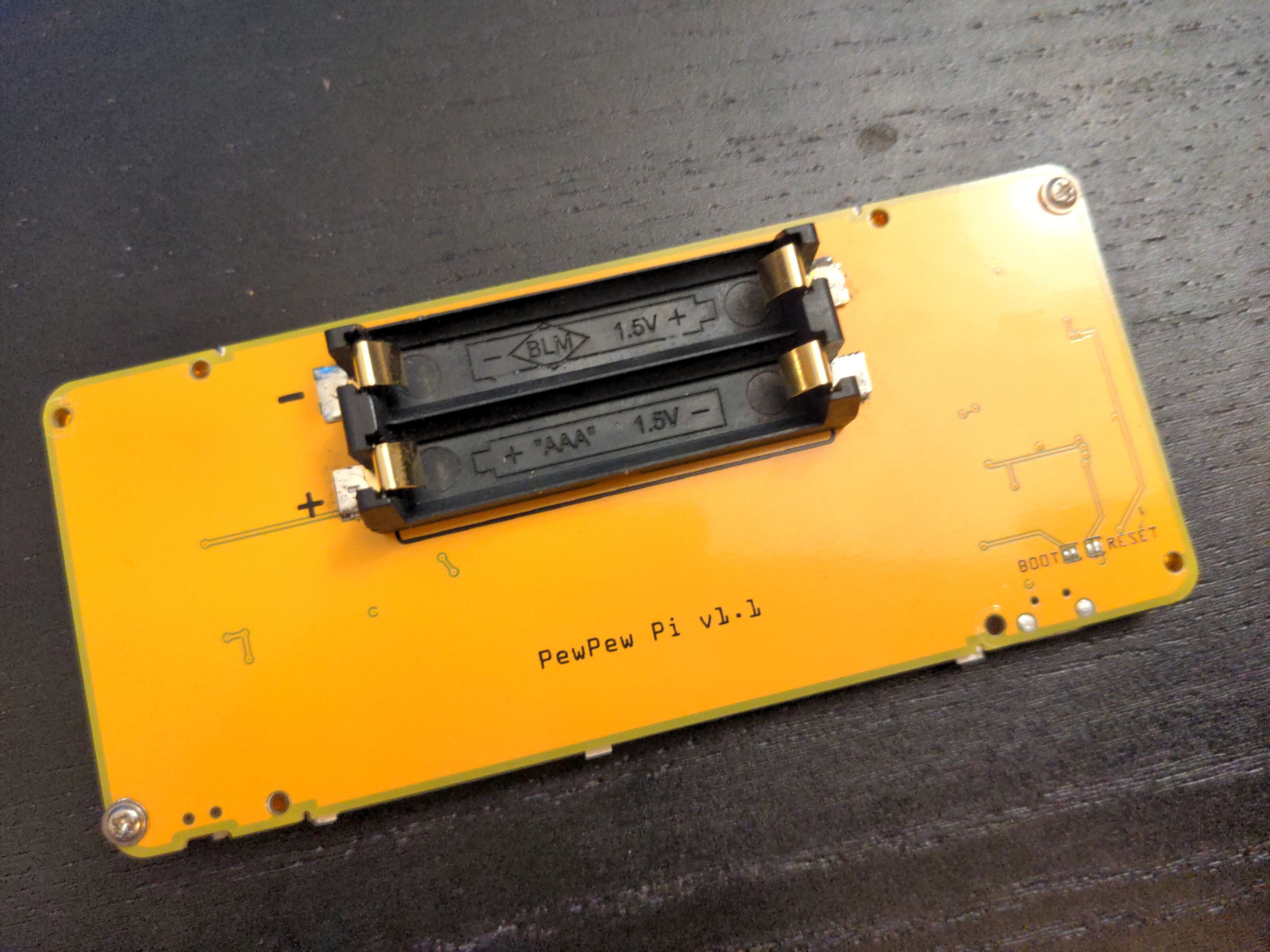
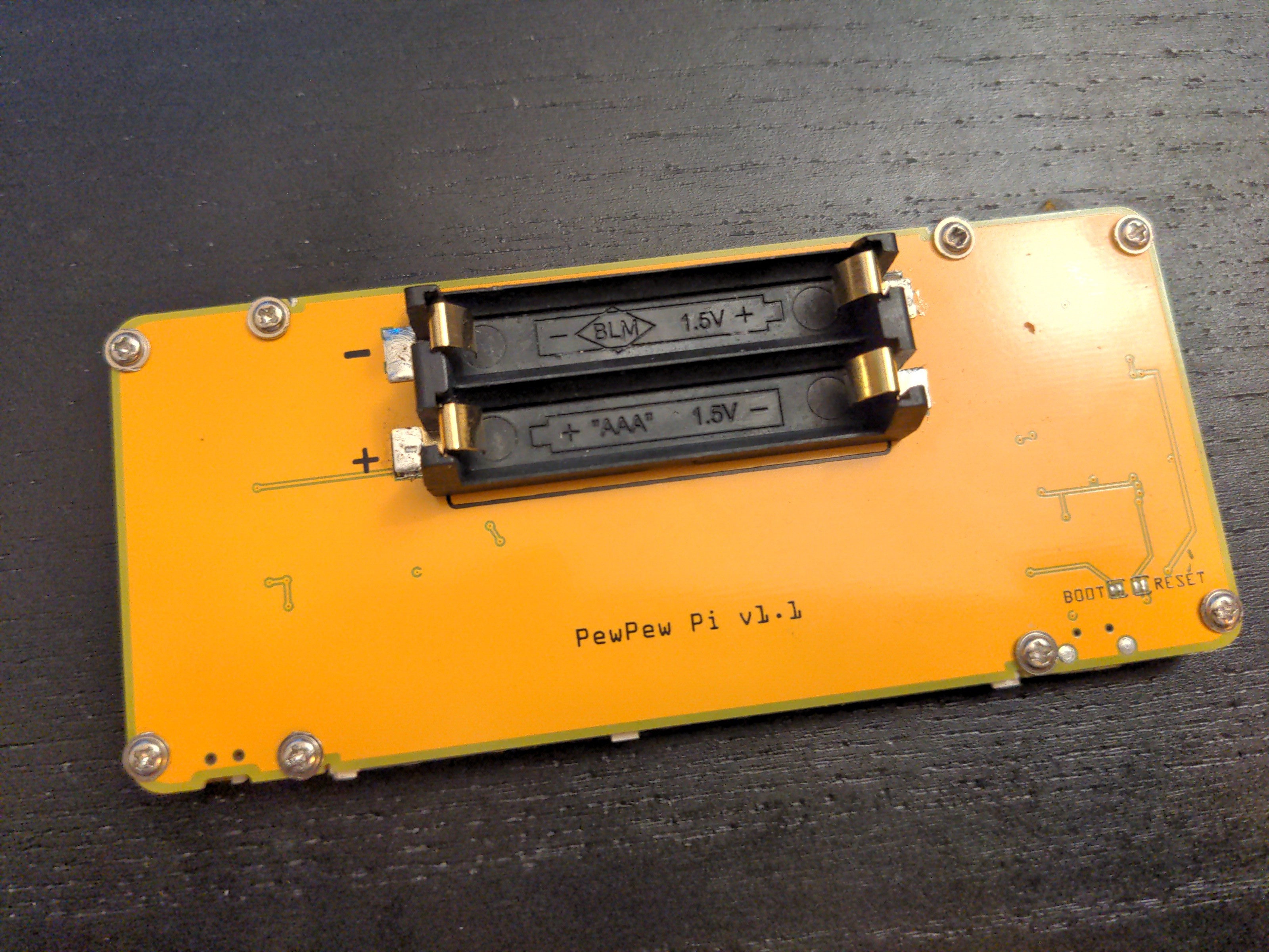
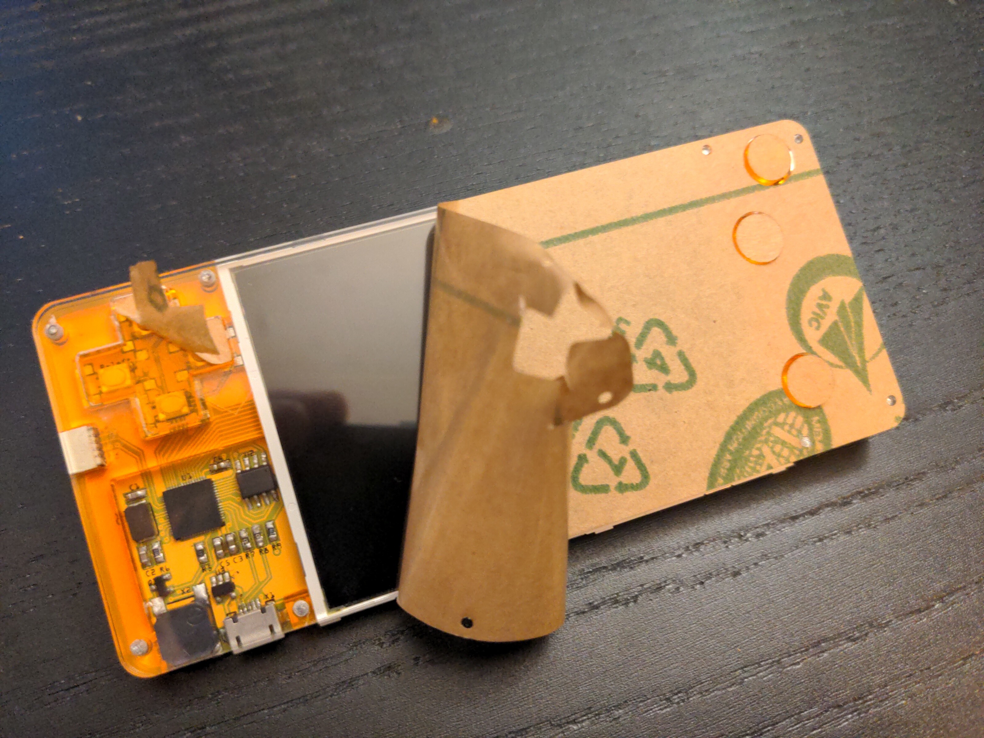
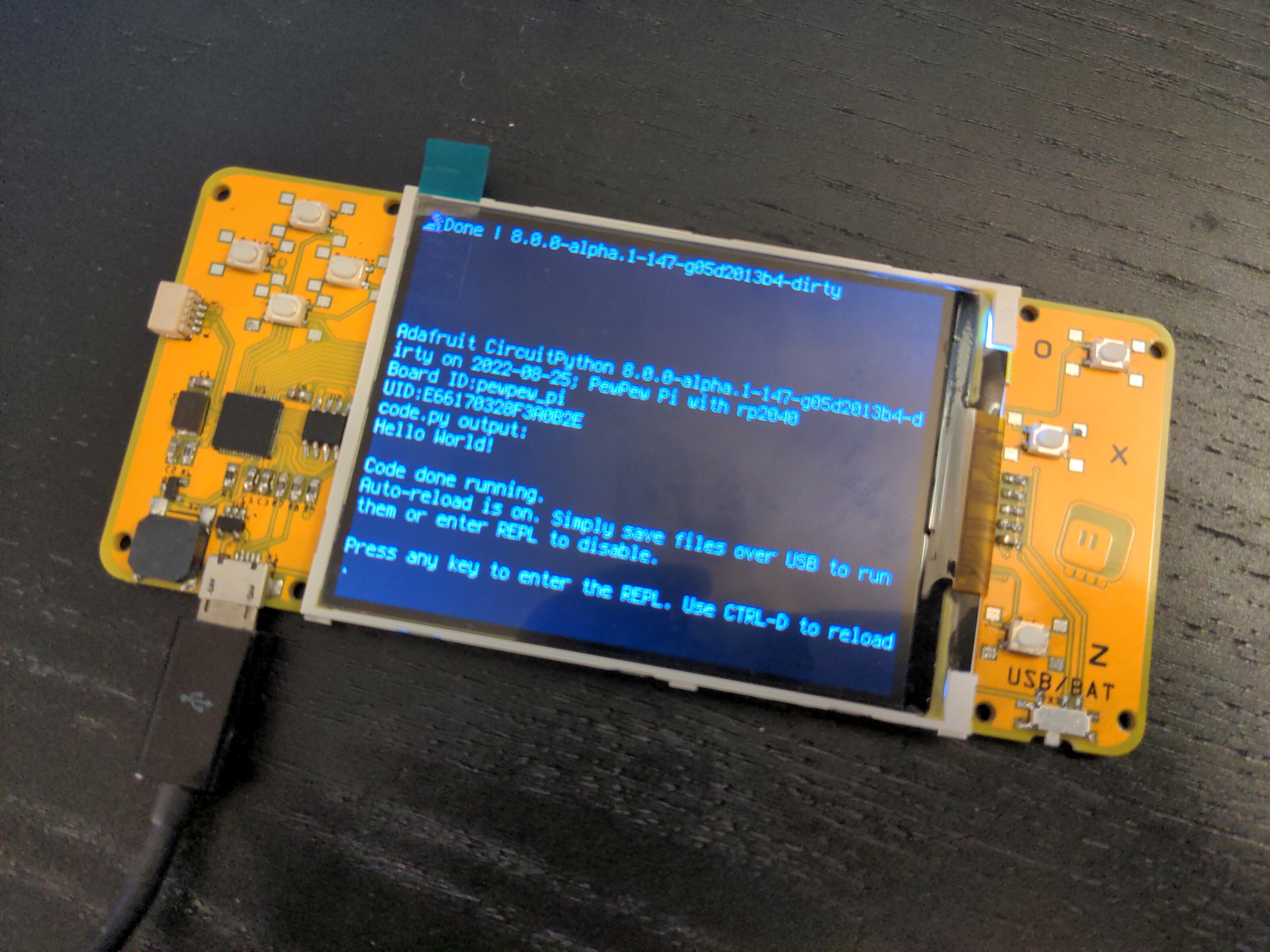
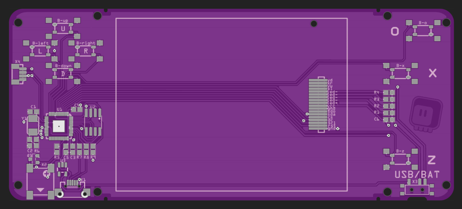
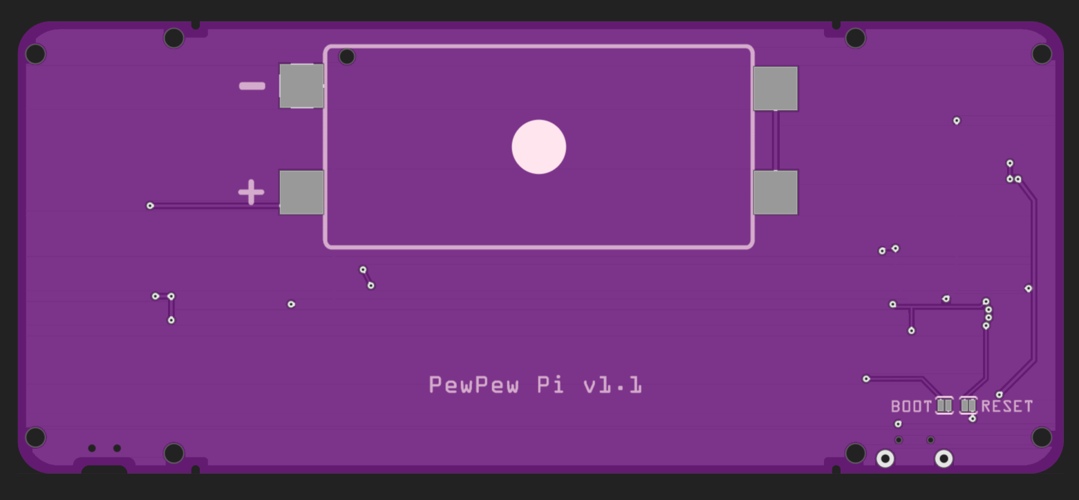
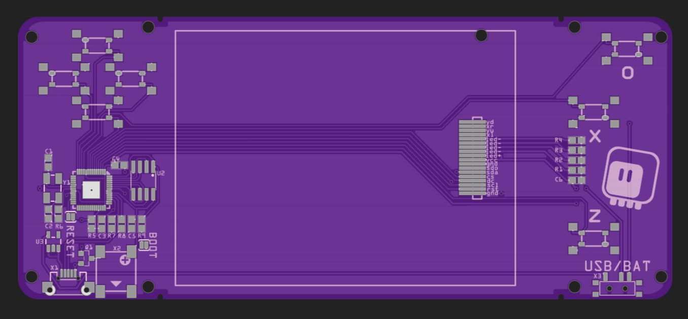
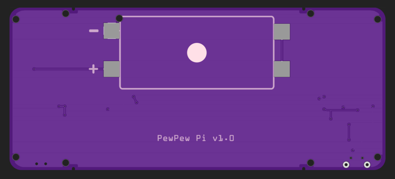
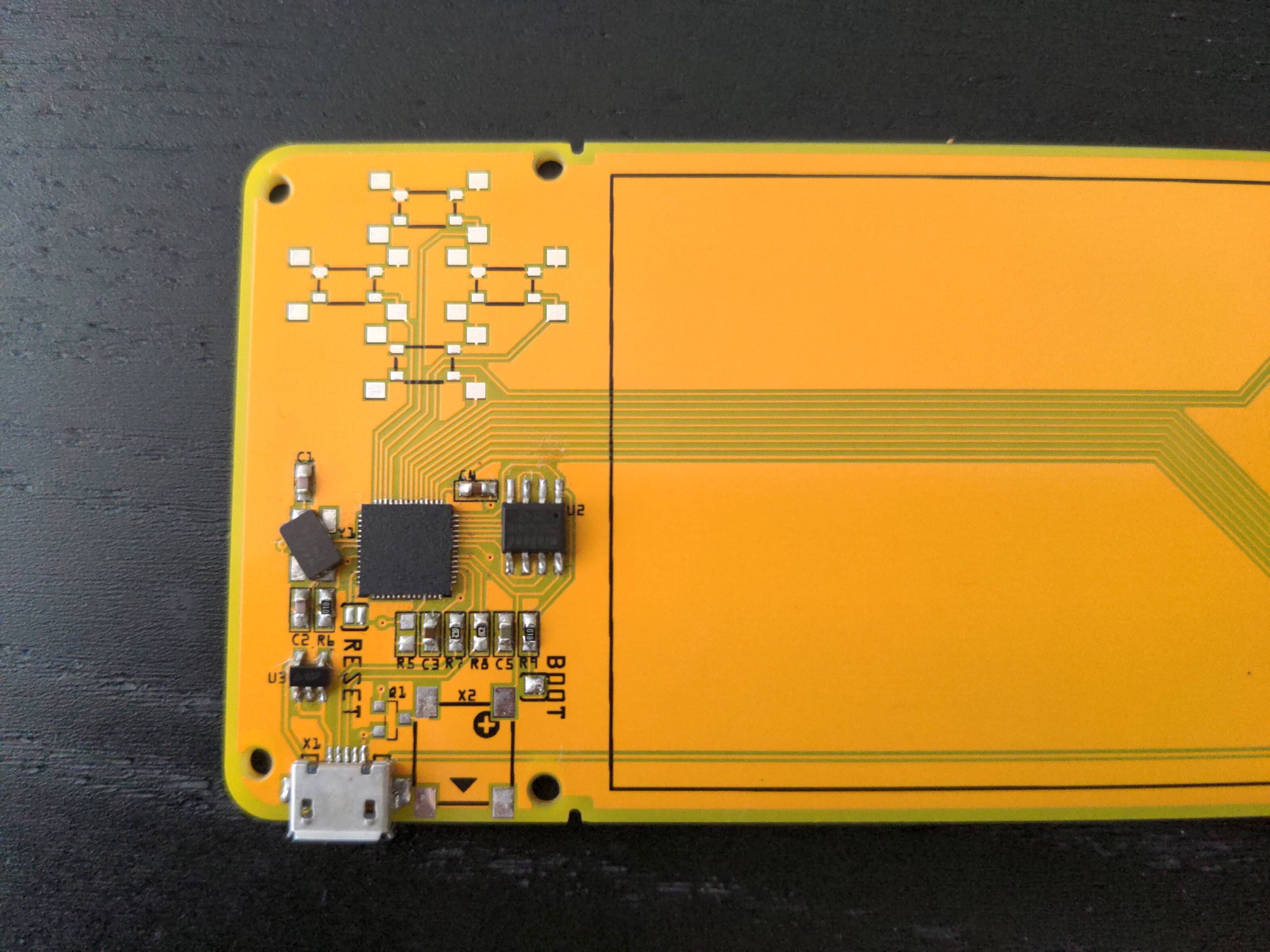
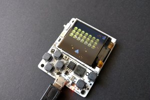
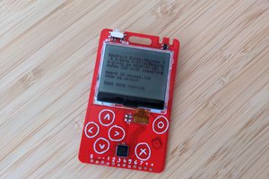
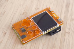
A comfortable gaming handheld for CircuitPython, continuing the work started with #µGame, through #PewPew M4 and #PewPew S2. A large 3.2" screen, an RP2040 microcontroller, 2MB of flash memory and a small speaker, all in a convenient form factor, with a laser-cut case and two AAA batteries for power.
0%
0%
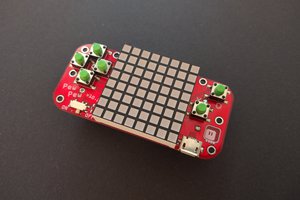
µGame 22
Continuing on improving CircuitPython gaming handhelds.
Become a Hackaday.io member
Already have an account? Log in.
Just one more thing
To make the experience fit your profile, pick a username and tell us what interests you.
Pick an awesome username
hackaday.io/
Your profile's URL: hackaday.io/username. Max 25 alphanumeric characters.
Pick a few interests
Projects that share your interests
People that share your interests