 Seth Fleming-Alho
This project borrows heavily from https://hackaday.io/project/20458-osug-open-source-underwater-glider and that project was used as a starting point for the build you will see below.
Gliders are an indispensable tool to oceanographers because they can help them collect important data such as temperature, salinity, pressure and oxygen among other things right from the surface down to hundreds of meters. The ability to collect data to such depths paired with the distances the gliders can travel and their capacity to operate in any season or weather gives oceanographers invaluable insight into the current conditions in our oceans
We wanted to build an undersea glider because the design lends itself to being very energy efficient. Ballast engines do not require a constant source of energy, they only need to pump water in at the surface and pump it out at depth to rise again. The act of sinking and floating combined with wings propels the glider through the water. Currently gliders on the market are capable of month long missions and communicate over satellite networks. These commercial gliders cost hundreds of thousands so it is our goal to create a much more affordable solution so as to potentially harness the power of citizen scientists in order to have better oceanographic models with wider coverage.
To start the project we began constructing the OSUG. Our hopes were to build the glider, add cellular communications and more batteries along with a few sensors such as temperature, pressure, salinity and possibly oxygen later in the build. If we could accomplish the above the glider could be used both as a outreach/demonstration piece and as a tool for oceanographers.
While constructing the OSUG the first hurdle was making it wireless. The original OSUG was designed to use a BlueROV tether combined with their pixhawk for controlling it. We decided to utilize an Arduino mega due to the large number of available pins and its ability to relatively easily interface with most actuators and sensors. Since the glider needed to be completely sealed and the more times a glider is opened and close the bigger the chance for a leak to happen we opted to also include a raspberry pi in order to wirelessly reprogram the Arduino. These two changes meant we had to redesign the circuit rack from the OSUG. The roll-motor also proved us with a challenge, 3d printing difficulties lead us to eventually abandon the stepper motor paired with a planetary gear setup. The stepper and planetary gear were both replaced by a high torque servo, this reduced the number of wires required, simplified the code and removed the need for limit switches. The pitch-motor assembly went smoothly, we successfully built it following the OSUG plans and the only change made was printing two of the battery holders and doubling the original OSUG's 18650cell capacity. The ballast engine is where we ran into our biggest hurdle, after constructing the syringe design of the OSUG we discovered that it simply couldn't handle the pressure at the depths we wanted to reach as well as it would seize even after lubrication if it was left to sit for an extended period of time (~a day). We decided to overhaul the design and copy what the commercial gliders use, a pump and ballast system. Finding an adequate pump proved challenging and we settled for a small diaphragm pump rated to 3bar of pressure, not ideal but suitable for a proof of concept.
The state of the project as it stands right now is a glider capable of diving, surfacing, turning left or right and collecting and logging temperature and pressure data. It requires a new command on every surfacing through a long range radio with a theoretical range of 2-5km. It currently has enough battery capacity to run for a full day continuously, maybe a touch more, with all actuators moving and sensors running, however on an actual mission it would not be continuously pumping water or operating solenoids, steppers and servos so...
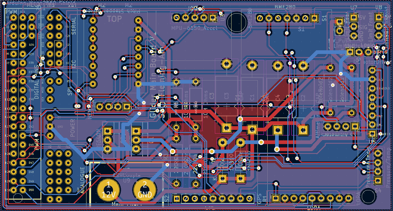
Read more »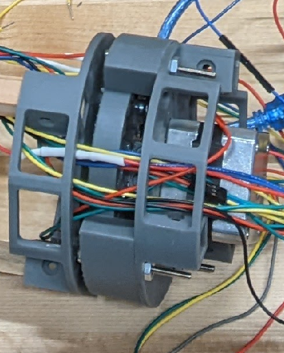 Figure 1
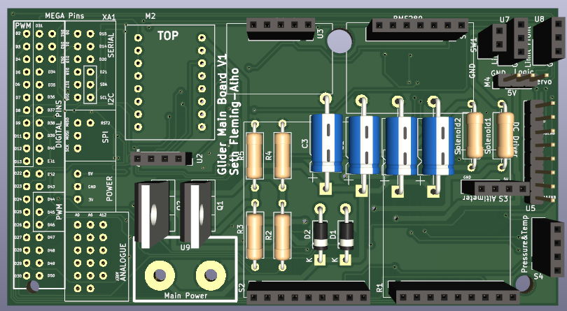
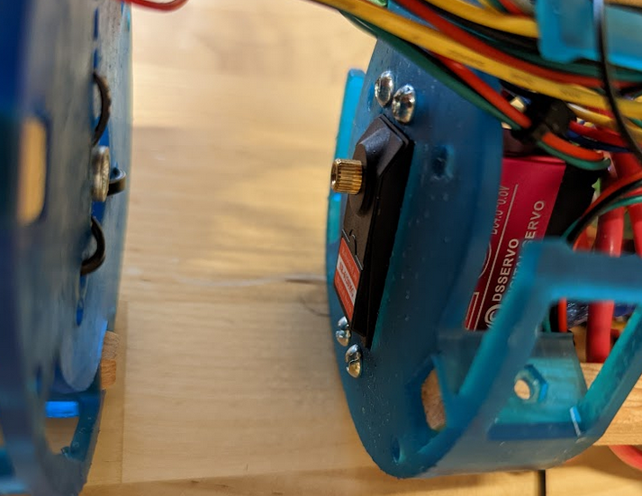 Figure 2
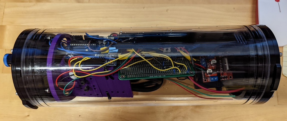
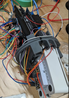 The original plan was to use an Arduino for full control of the glider. Cellular communication could be established while on the surface and dead reckoning would be used subsurface. For prototyping purposes we opted to use long range radio control. We also wanted the ability to reprogram the glider quickly and without needing cables so it was decided that a raspberry pi would be included in the design. The Pi is used to control the Arduino and reprogram it on the fly through WiFi, this saves us from needing to open the glider for every adjustment. We also wanted the ability to power off any actuators while reprogramming to avoid any accidental damage so a second power supply was added purely to support the raspberry pi in the form of a portable phone charger.
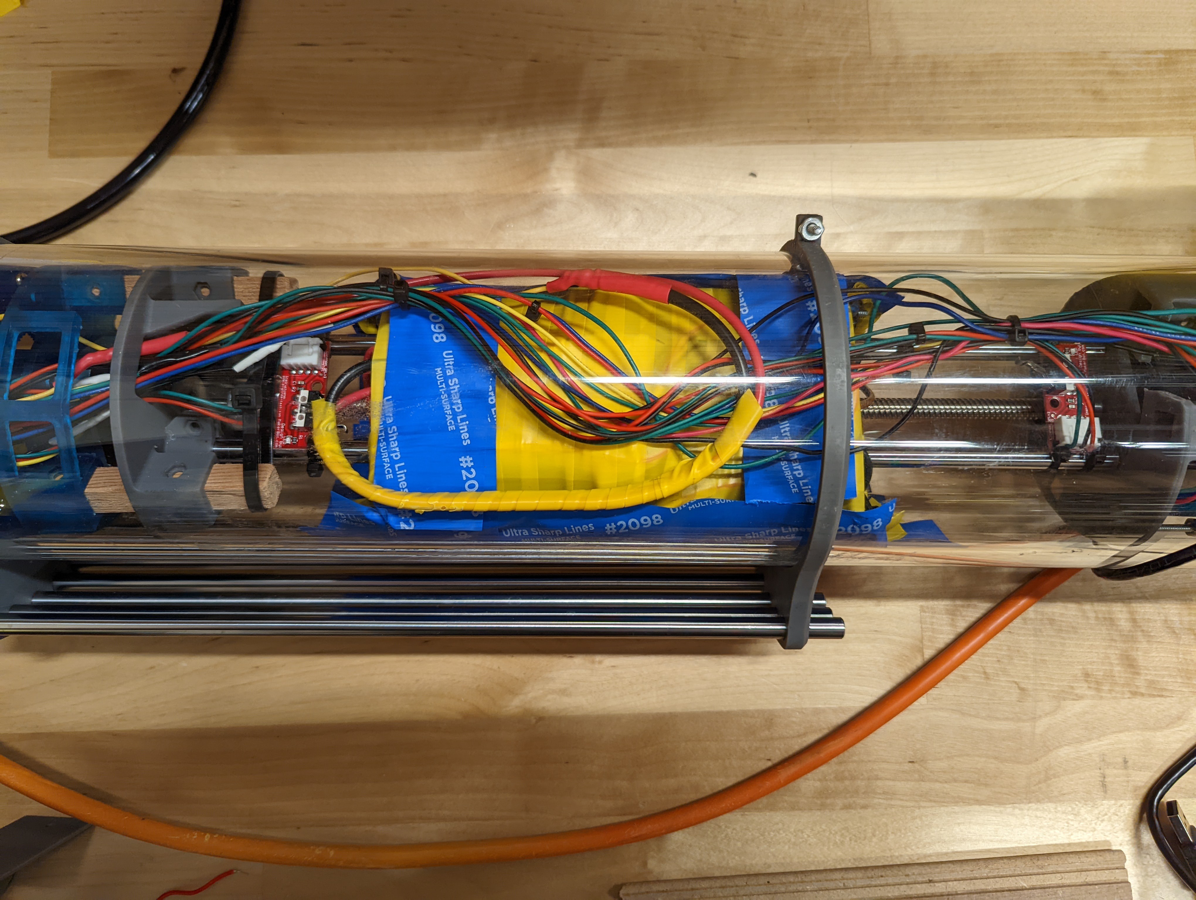
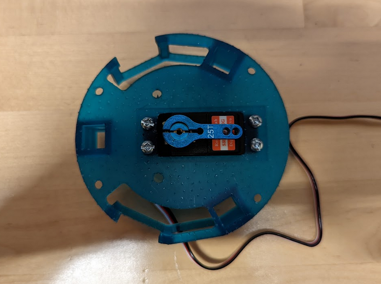
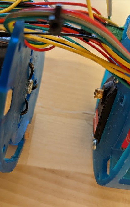
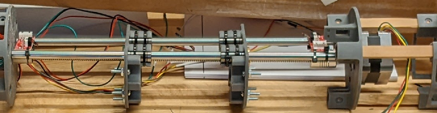 Here is a skeleton view of the pitch battery system.
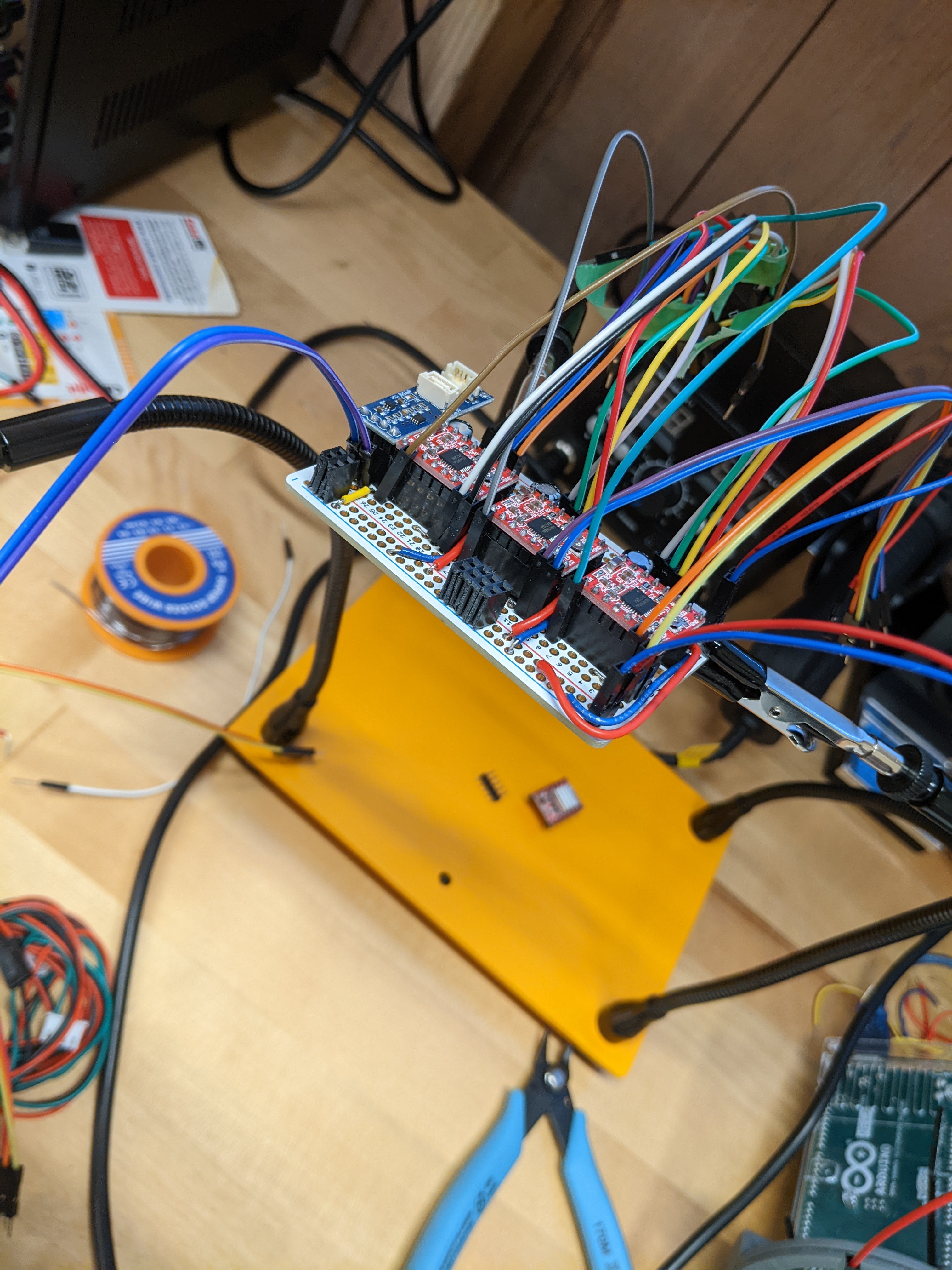
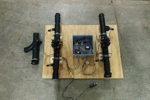
 This design included two solenoid valves rated for 100PSI, a control board, and arduino uno and a diaphragm pump rated to approximately 30meters of seawater with a lifting bag as a bladder.
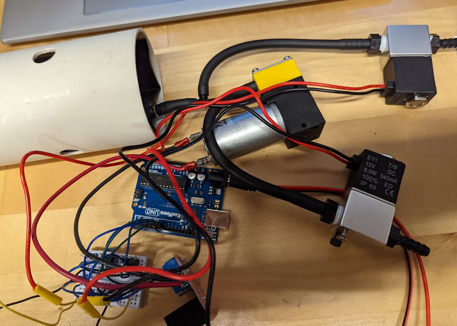
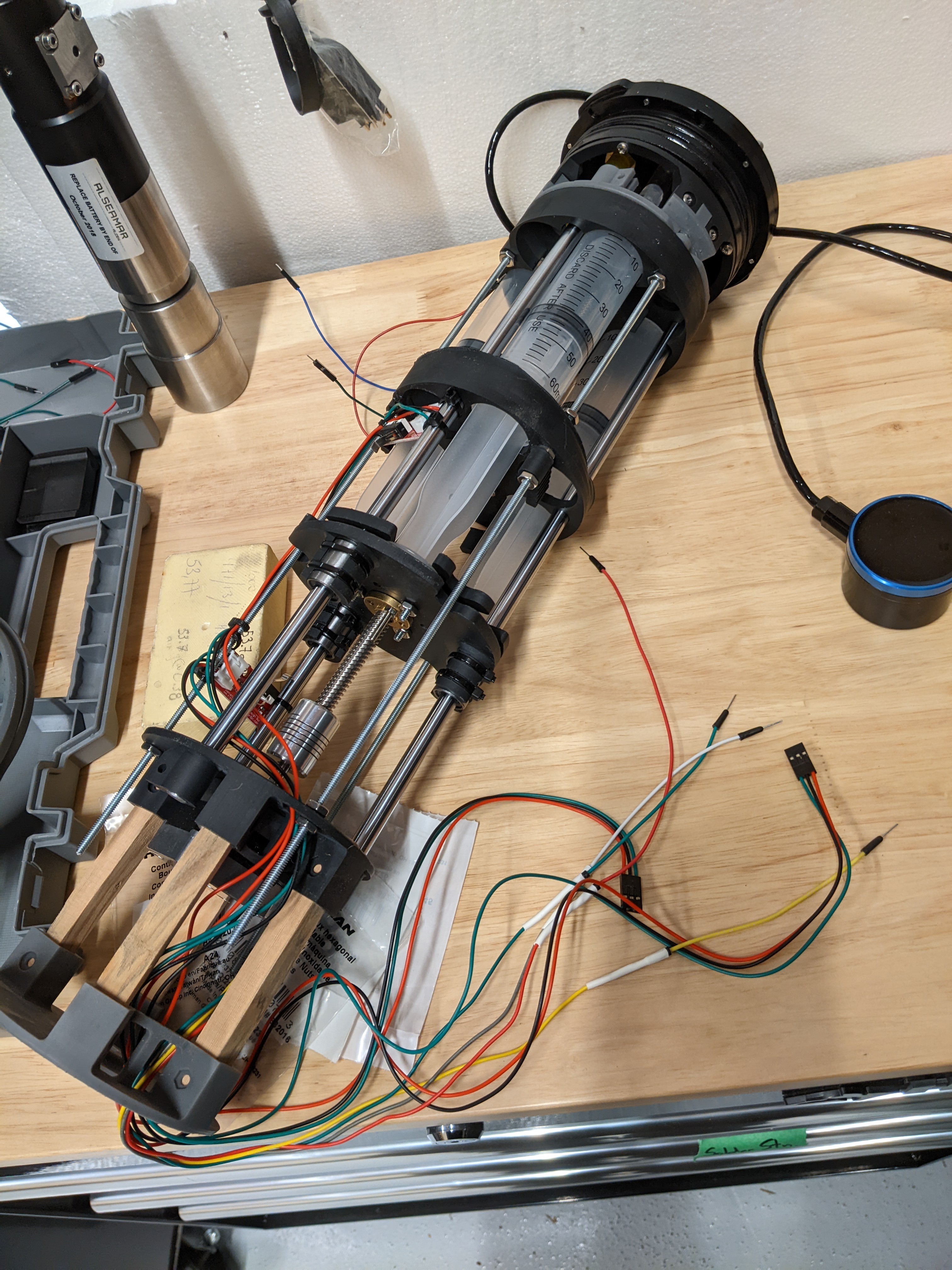
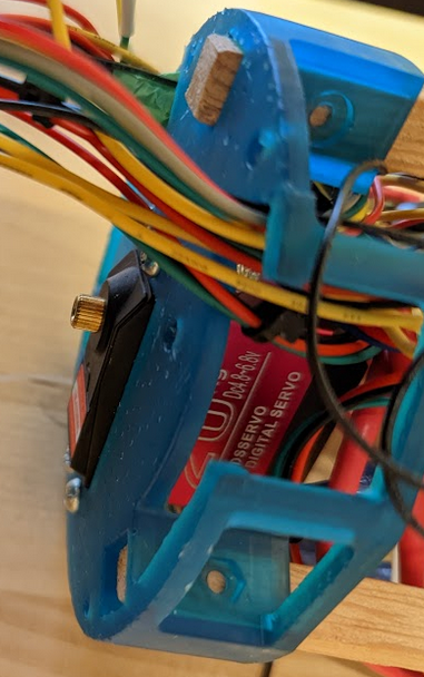
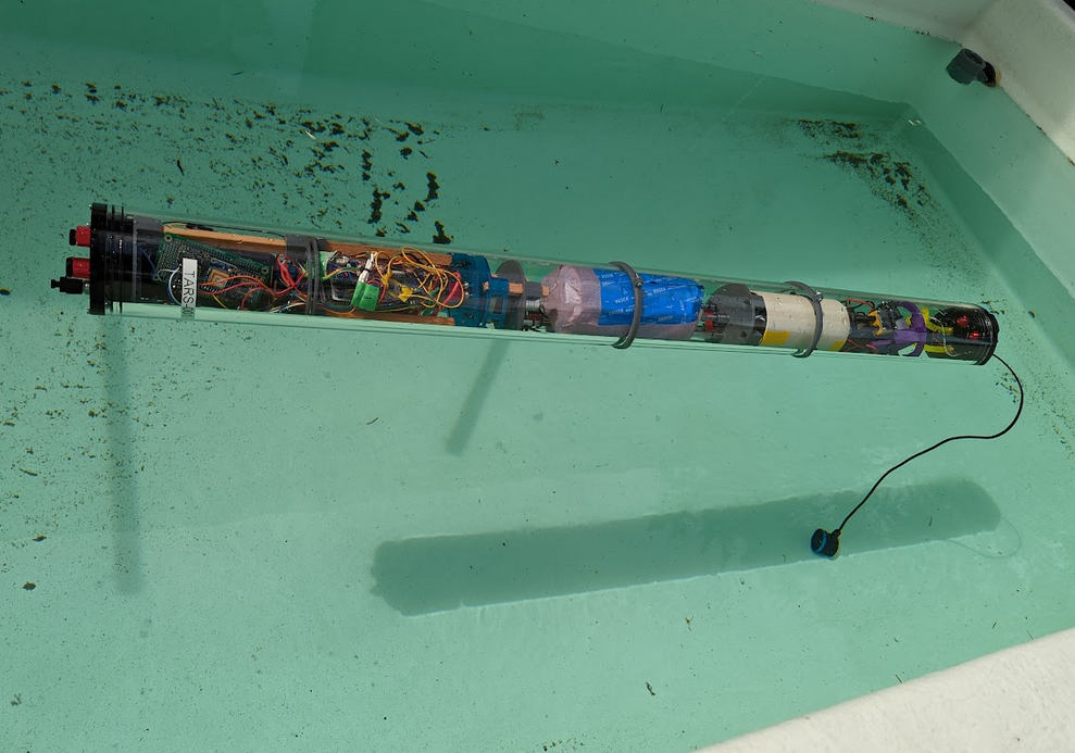 In this image the wings have not been attached and the altimeter is hanging loose as the nosecone is also off for testing purposes.
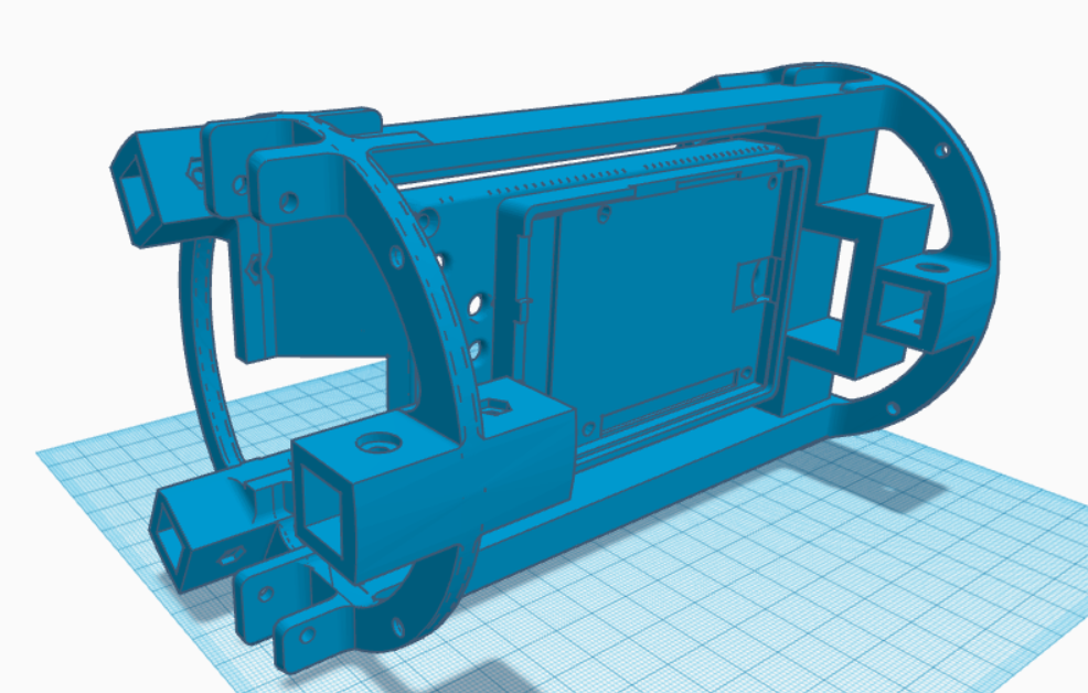

 andyknitt
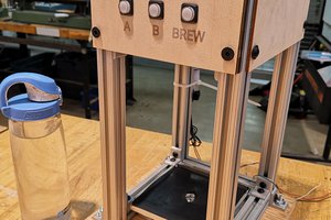
 Sean Morton
 bram
bram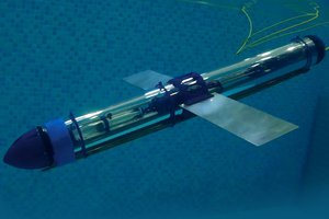
 alexw
alexw