 AIRPOCKET
FEATURE
This device is intended to be a DIY alarm system that can be built using Spresense and as many readily available components as possible. We envision this device to be used by people living in mountainous areas or on slopes in the foothills of the mountains, where it can be easily installed behind their homes or on their property.
The basic principle of operation of this device is to sense changes in the inclination of an erected pile.
Our research into existing technology shows that similar concepts already exist. However, since it is necessary to operate a large number of devices to detect predictive phenomena that can occur anywhere, a key issue is to further reduce the cost of the devices.
The main focus of this project was not to develop a multifunctional device, but to develop a device that is easy to operate and can be implemented as easily as possible by people with no knowledge of electronics or electricity.
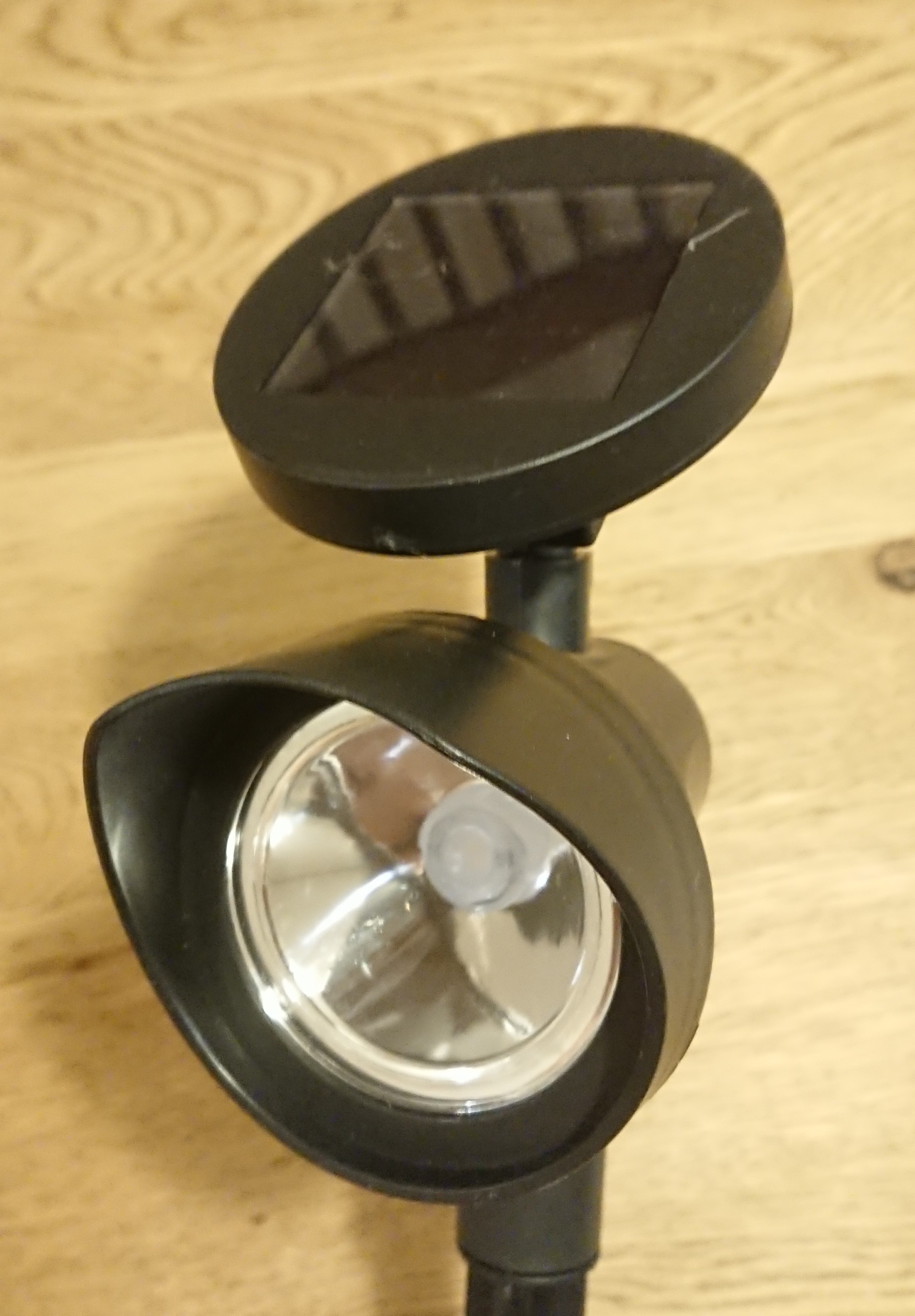
The main functions of the device can be implemented by using common garden lights or by combining components that can be purchased in stores.
Main Functions and Features
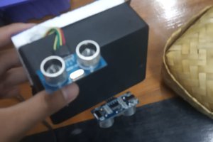
- Easy installation by simply sticking the device into a garden-light enclosure
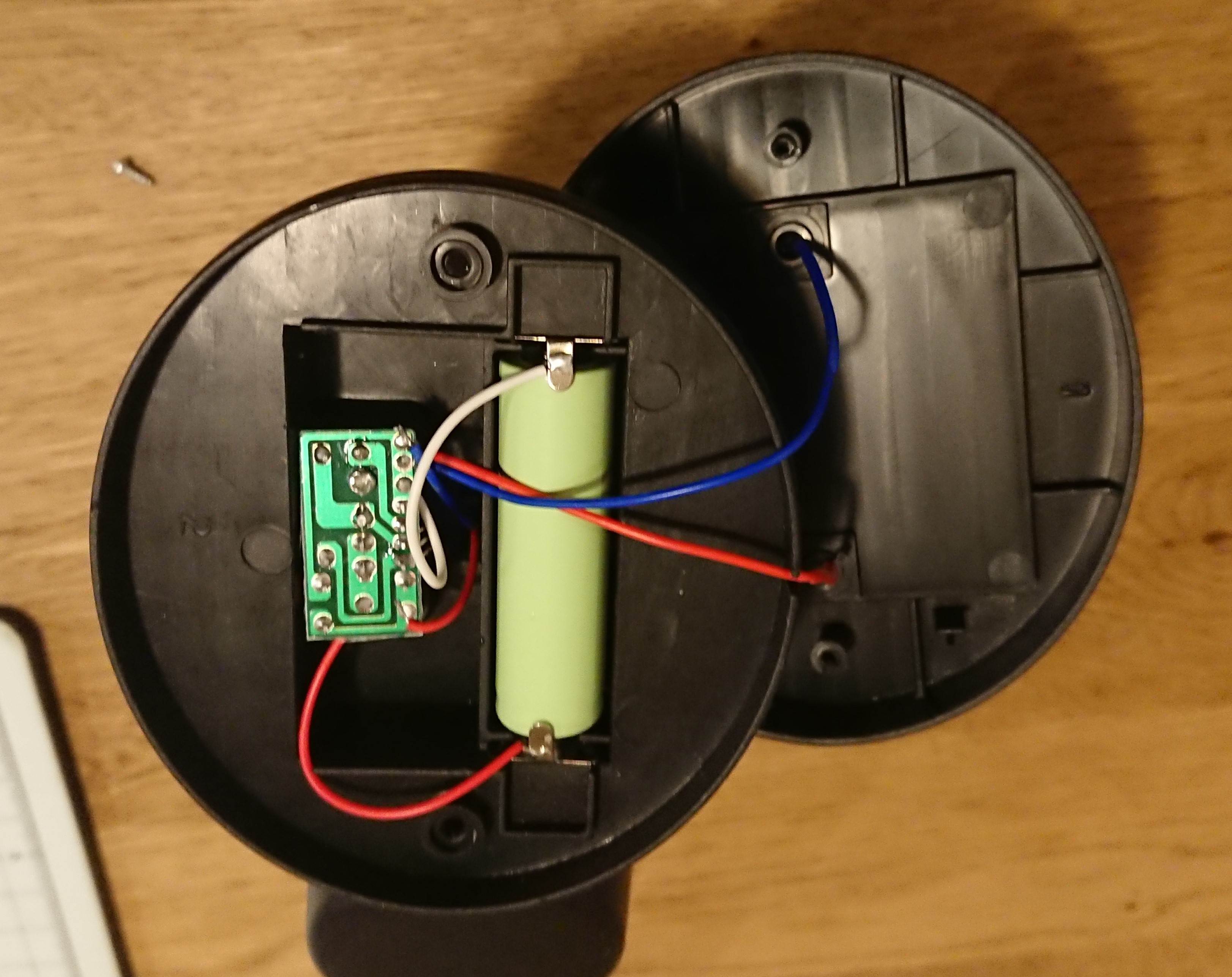
- Detects changes in the tilt of the device using an acceleration sensor
- Alert indication by flash using LEDs of the garden light
- Transmission of alert signals via Wi-SUN communication
- Alert information is sent from the receiving device to an arbitrary terminal via MQTT
- Alert display device receives the alert information and displays the alert.
- Supplemental power supply by solar panel of the garden light
- Transmission and recording of data to google cloud(spread sheets).
- Management of data by google apps scrept
- Infomation management of each terminal and display of map information by smartphone apps(glide)
In operation
Field test.
Field test #2
Smartphon Apps
Installation
When installing the device, simply plug the device into the location you wish to monitor, stand it up, and turn on the power. (0:04~)
When the power is turned on, the acceleration sensor measures the tilt of the device and memorizes the initial state, and the startup completion status is transmitted via Wi-SUN communication.
The LED for alarm indication flashes once when the system starts up, and flashes twice after successful Wi-SUN communication to confirm normal startup. (0:14~)
When startup is completed, the system enters Deepsleep.
When no abnormality is detected
By default, Deepsleep is released every hour to measure the tilt. In the above movie, Deepsleep is set to 3 seconds for operation check. If the difference from the initial tilt is less than the threshold value (5° by default), the system sends a "no abnormality" status and the value of the angle change, and enters Deepsleep again.
When an abnormality is detected
If the difference between the inclination of the device after the release of Deepsleep and the initial inclination is greater than the threshold value, the LED of the garden light flashes and an alert status is sent via Wi-SUN communication.
Receiver-side device (Raspberry Pi 4B)
A Raspberry Pi 4B is used as the receiving device, and a Wi-SUN USB dongle BP35C2 is used to receive Wi-SUN communications.
It also serves as an MQTT server and sends alarm data to the alarm display device or any device.
Alarm display device (M5Stack)
When alarm data is received from the receiving device, it displays the ID of the sensor terminal that detected the abnormality, and indicates the alarm with text, background color, and alarm sound. (0:45~)
System Configuration
The overall system configuration is as follows

Spresense is used as the controller for the sensor section to calculate the device's tilt from the BMI160's accelerometer values. The measurement results are sent to the receiving device via Wi-SUN communication.
The receiving device, a Raspberry Pi, uses python for Wi-SUN communication and data processing, and Node-RED for running the MQTT server and...


 Stefan Wagner
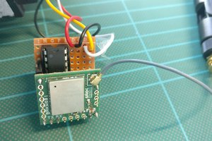
 Jean-Matthieu DECHRISTÉ
 dede rohmat
Excellent. Thanks for elaborating!