 Tinfoil_Haberdashery
One of the difficulties with using the Raspberry Pi in a build like this is that major ports are on adjacent corners, meaning unless your board is on a specific exterior corner, you won't have access to major inputs or outputs. Additionally, lots of the cables required stick out a LONG way from the board. The stock MicroHDMI cable, for example, is difficult to use in a way that doesn't double the effective width of the board.
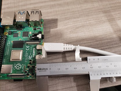
fig. 1: with strain relief, the micro HDMI nearly doubles the width of the board.
This can partially be dealt with by switching the Raspberry Pi to composite output, a strategy which will indeed be integral to this build but which will be discussed later. Still, things like power input and the TRRS cable that carries composite video are still annoying, not least because while I have 2 displays that take TRRS composite video input...both of them take it in a different conductor pattern than each other, or the pi.
I will therefore be soldering to the underside of the board for most of the relevant connections, including power, video, audio, and USB2.0.
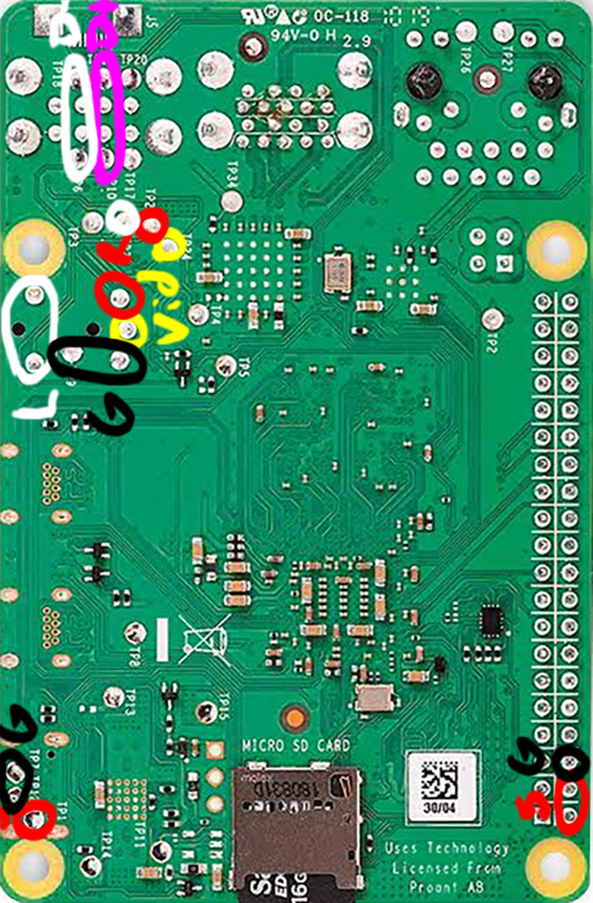
Some probing with a continuity meter reveals relevant I/O connections and their associated test pads on the underside of the board. At some point in the future I'd like to design a circuit board that uses pogo pins to distribute signals from these contacts, but for the initial build I'm planning to simply solder wires that serve that purpose.
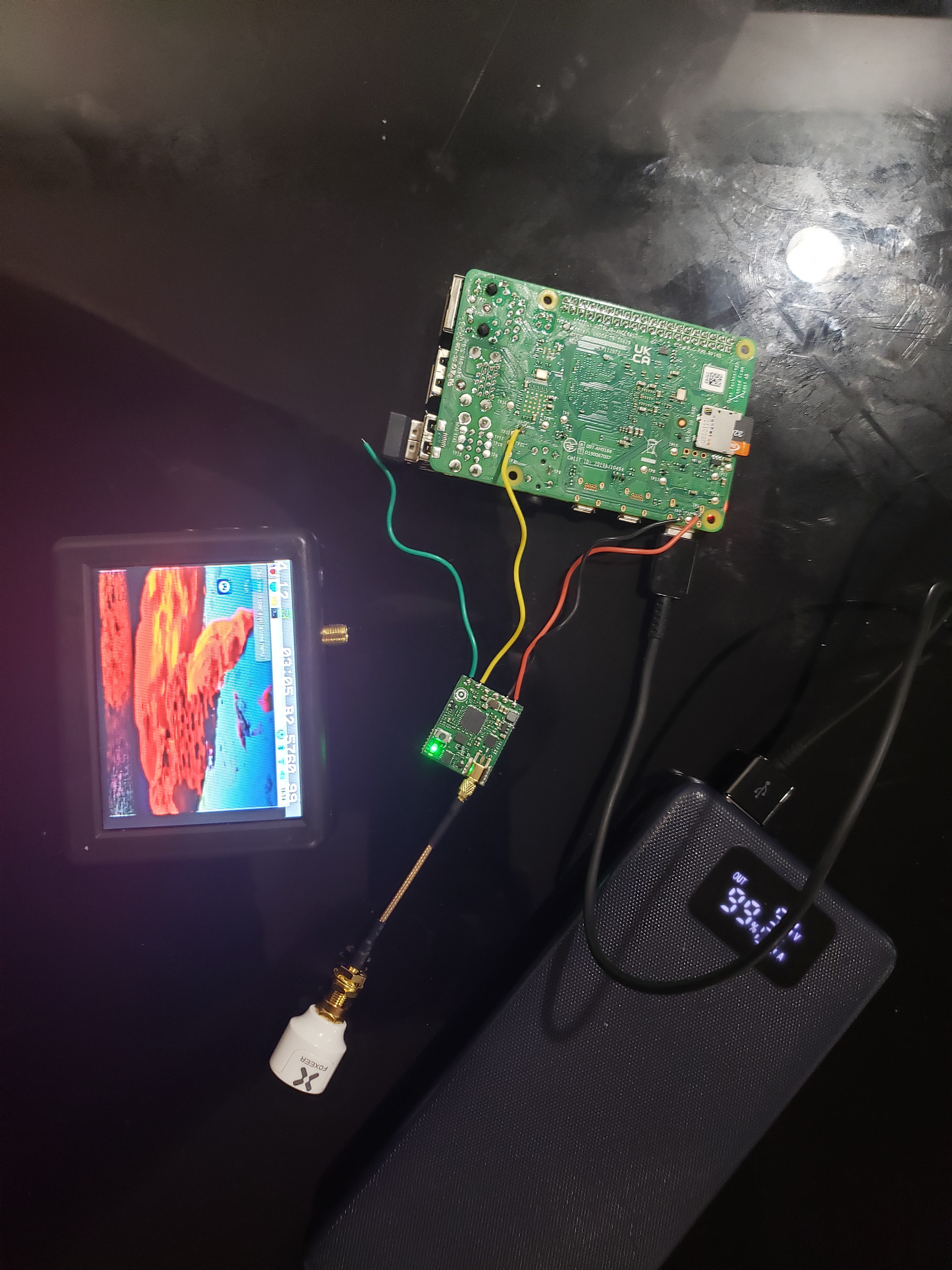
Preliminary tests are promising. Hooking up a 5.8ghz VTX to the composite output on the pi lets me get wireless video to my outboard screen.
Discussions
Become a Hackaday.io Member
Create an account to leave a comment. Already have an account? Log In.