Close
0%
0%

Solar Powered WiFi Weather Station V4.0

An affordable Open Source Weather Station for Everyone

Similar projects worth following
This is an affordable weather station for various applications like smart agriculture, smart city, solar plants, construction site, etc.

It consists of two nodes, the Sender Node will be deployed in the field ( where internet is not available ) and the Receiver Node will be kept indoor where the internet is available for uploading the weather data to the internet.

The main goal of this project is to read the weather parameters by using various sensors, process the data through an ESP32, and then transmit them through the LoRa module. The receiver LoRa unit will collect the data from the Sender node and uploads it to the Server for monitoring and analysis purpose.

The received data can be observed in multiple ways:
1. Monitor the data through e-Ink Paper Display
2. Integration with Home Assistant / ESPHome
3. Upload the data to Thingspeak and monitor the logged data in a graphical format.
4. Monitor the data on smartphones through the Blynk App.

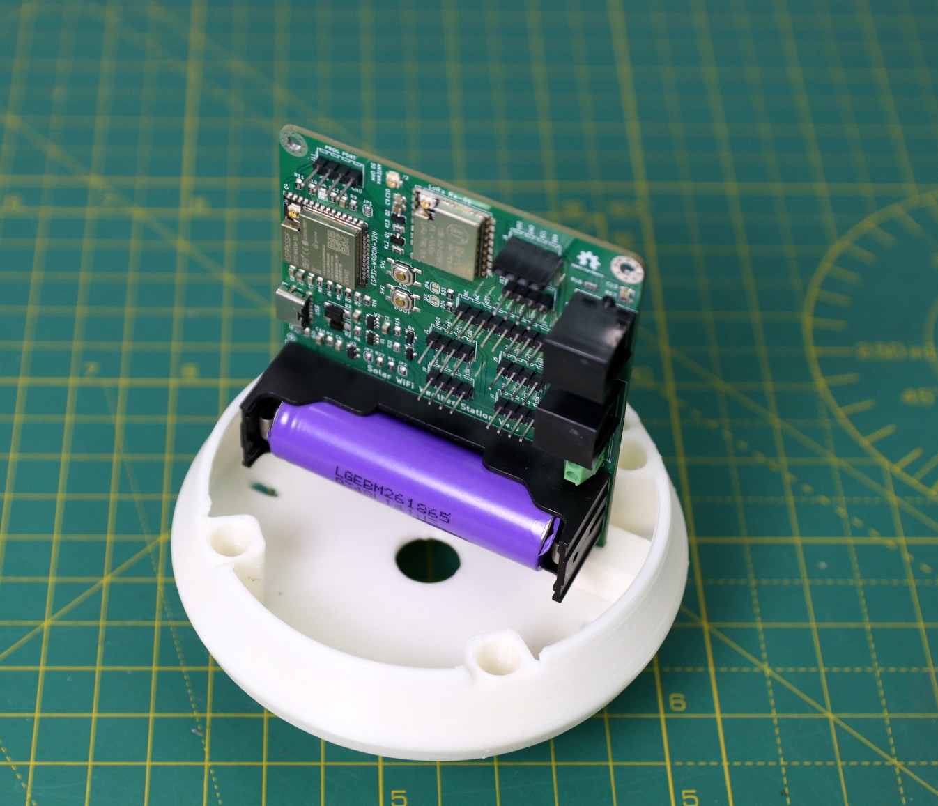
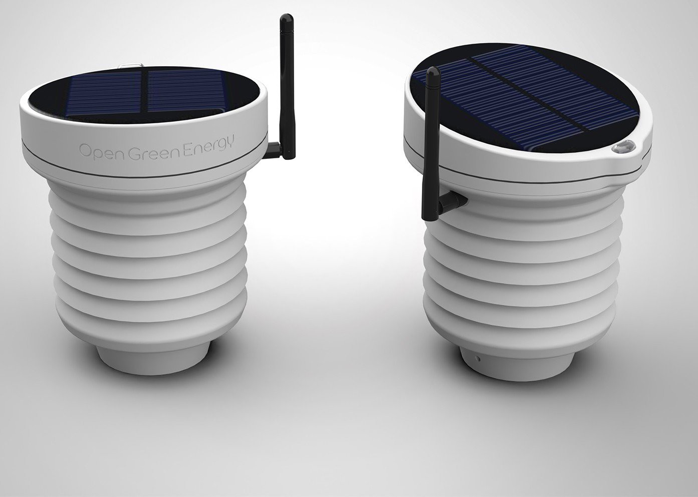
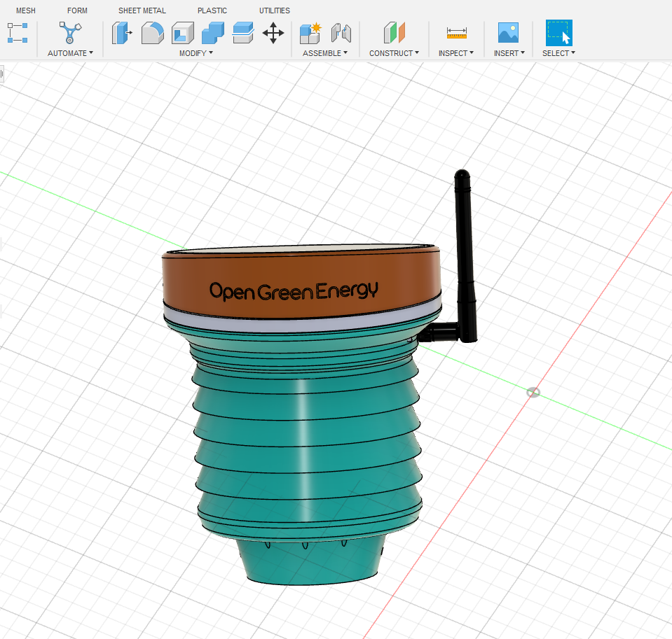
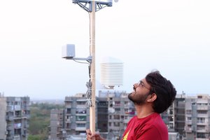
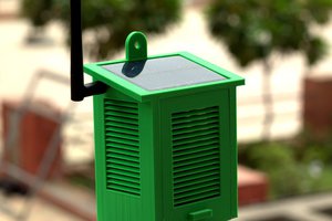
My goal is to make a Solar-powered wireless weather station that can be deployed in a remote location where there is no internet connectivity. I am planning to use a LoRa module to achieve long-range data transmission.

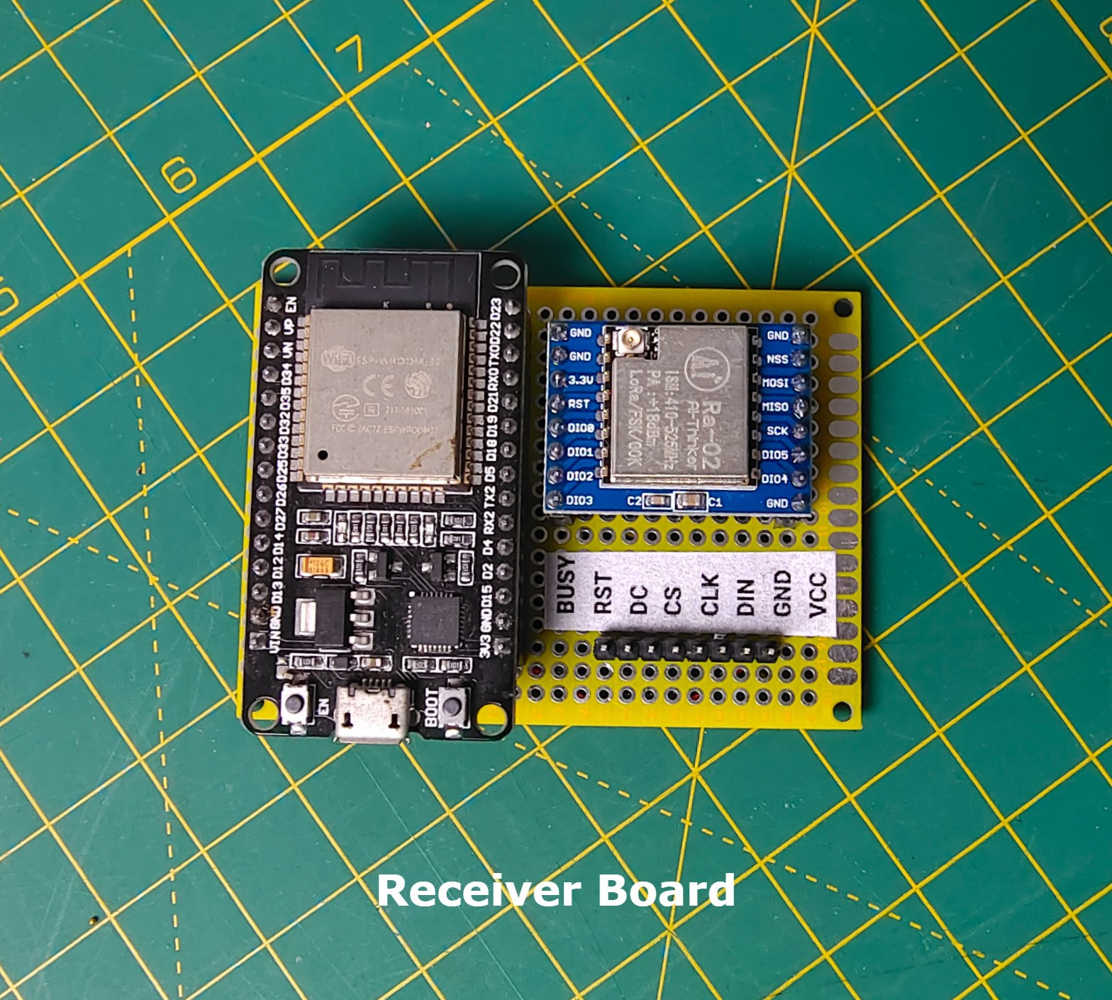
LoRa is a wireless connectivity technology supporting the internet of things (IoT) system. The use of the LoRa network will increase the range of wireless communication that can reach distances of up to 5 kilometers with ultra-low power consumption. One more advantage is that one LoRa network cell can connect end devices to hundreds of nodes.

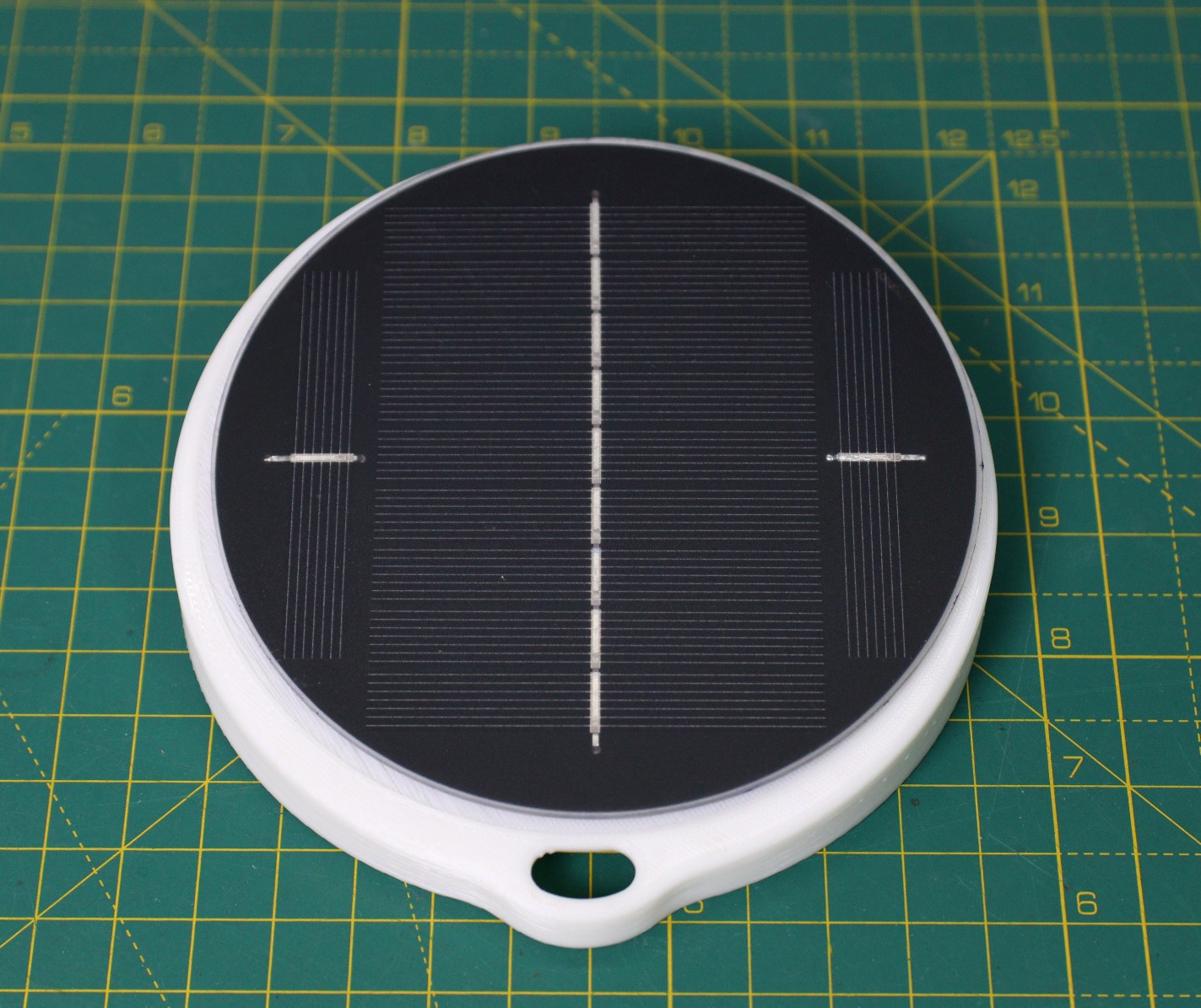
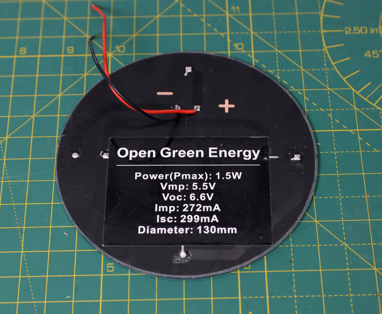
The weather station will be fully solar-powered, so no need to worry about the external power supply. You can install it in a remote place without laying long cables to provide power.

I have earlier posted two Instructables on Weather Stations ( Version -1.0Version-2.0, Version-3. ) that are very popular on the internet. Based on the user's feedback, I tried my best to make a more powerful weather station by including new features.

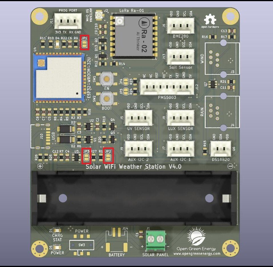
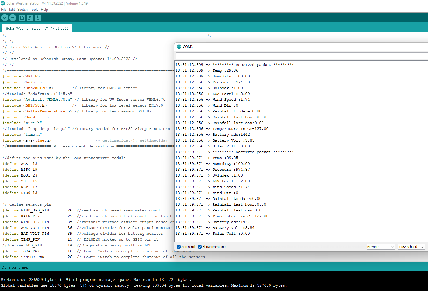
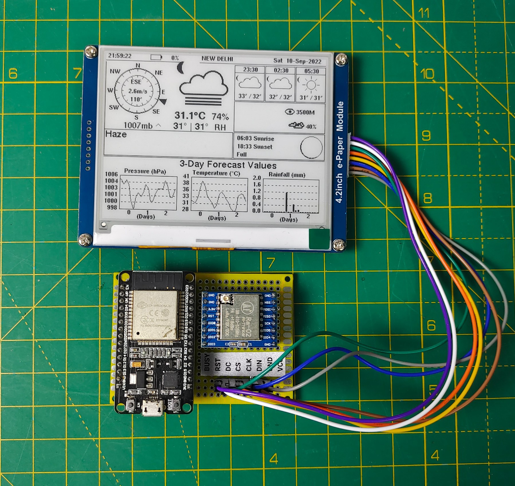
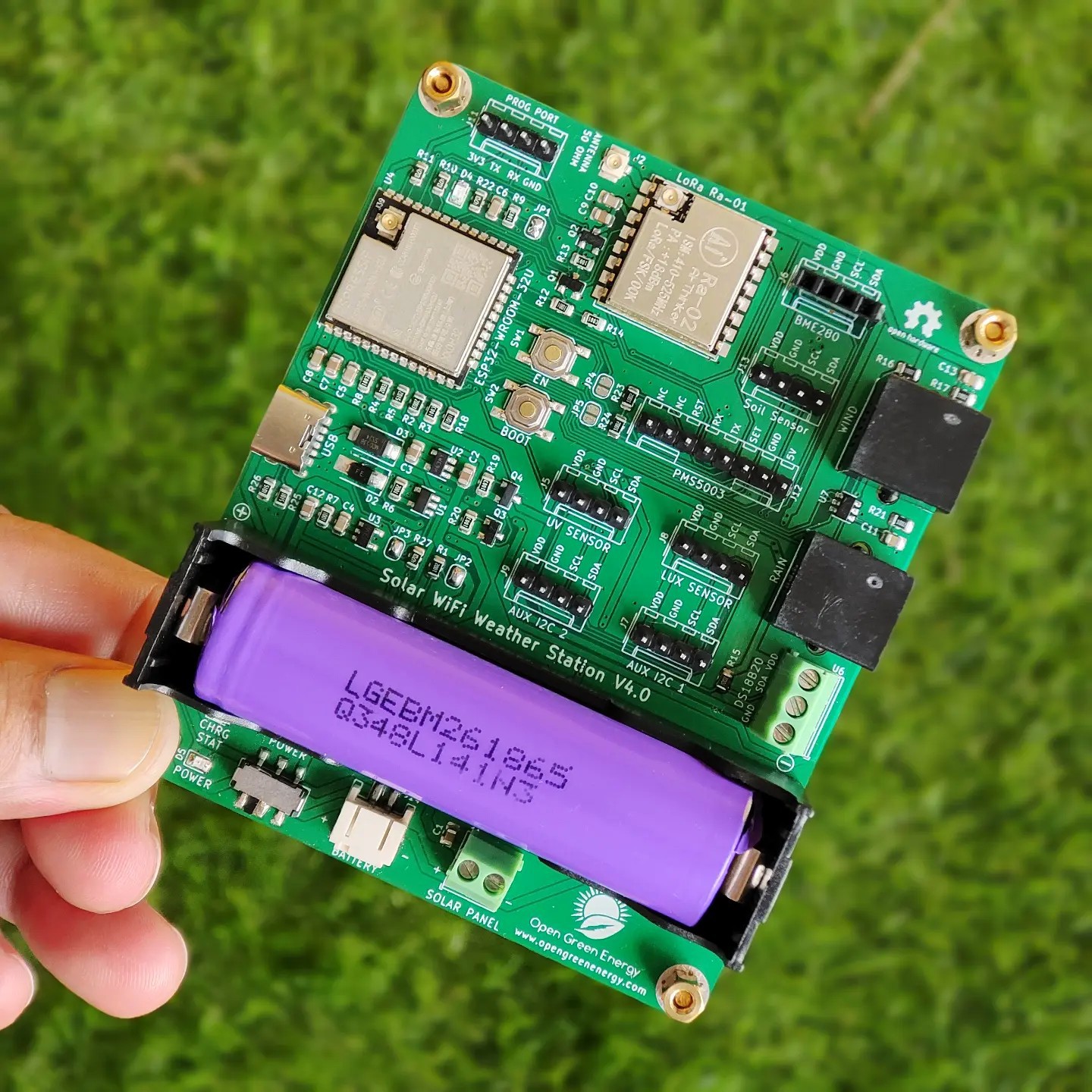
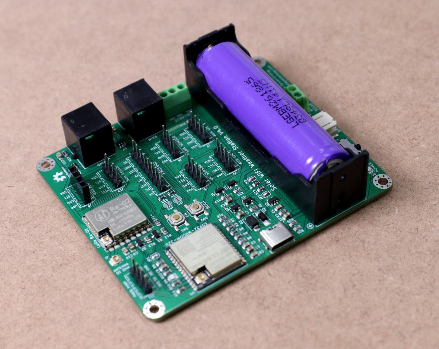
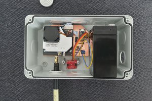
This Weather Station is such a compact weather station that consists of several meteorological sensors that measure the following parameters:

1. Internal Temperature (BME280)

2. Humidity (BME280)

3. Barometric Pressure (BME280)

4. External Temperature (DS18B20)

5. Wind Speed ( Sparkfun Weather Meter )

6. Wind Direction ( Sparkfun Weather Meter )

7. Rain Gauge ( Sparkfun Weather Meter )

8. UV Index ( SI1145)

9. Lux Level ( BH1750 )

10. Air Quality - PM1.0, PM2.5,PM-10 ( PMS5003 / 7003) 

11. Soil Temperature and Humidity ( SHT10 )

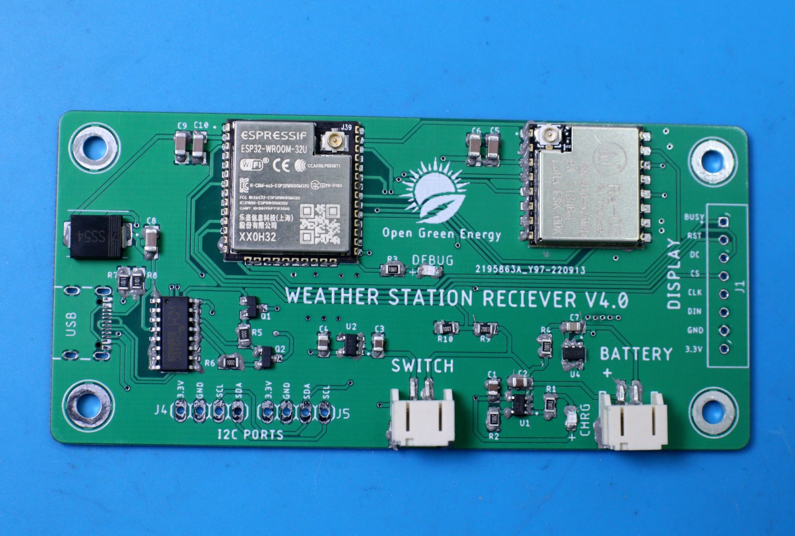
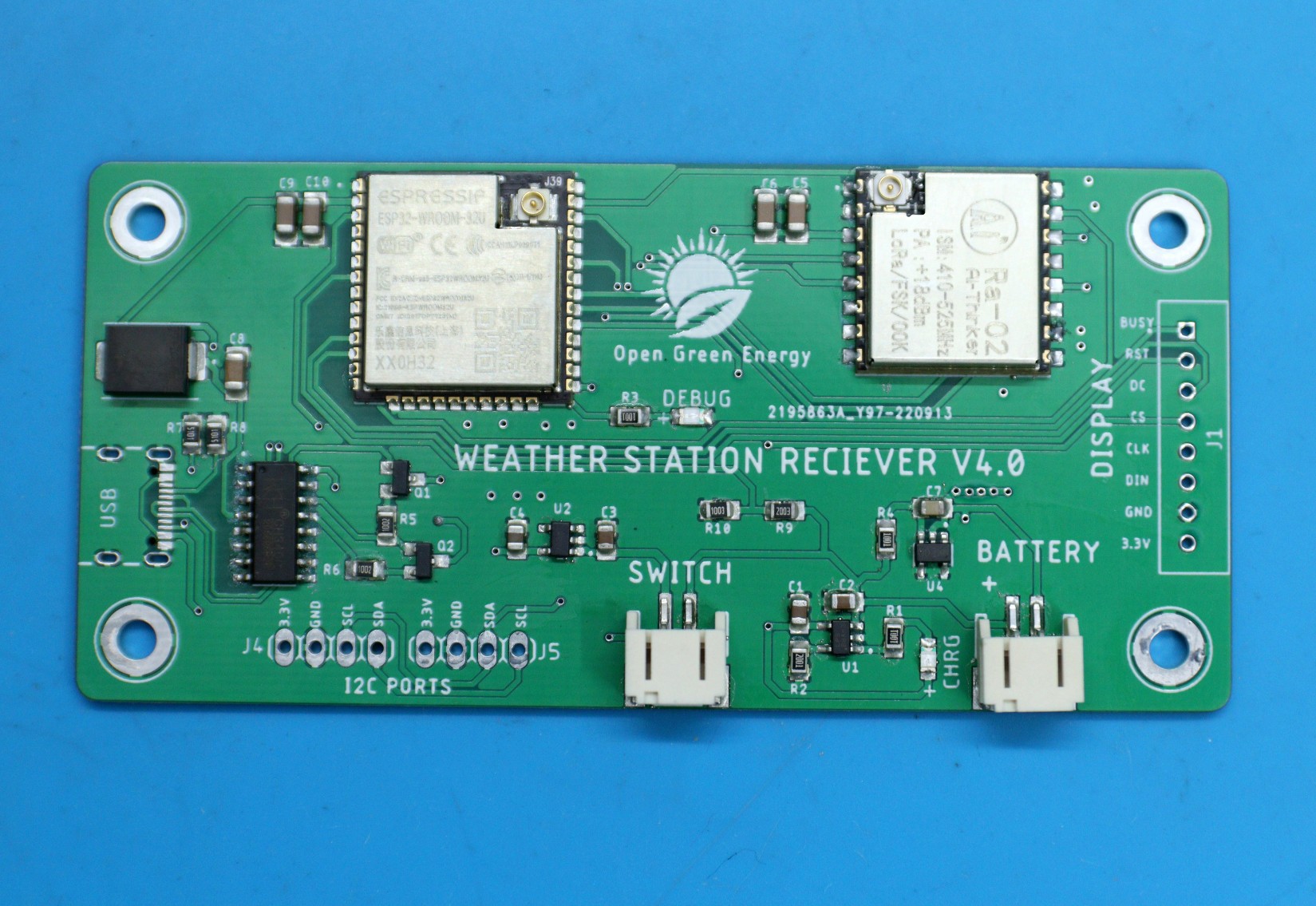
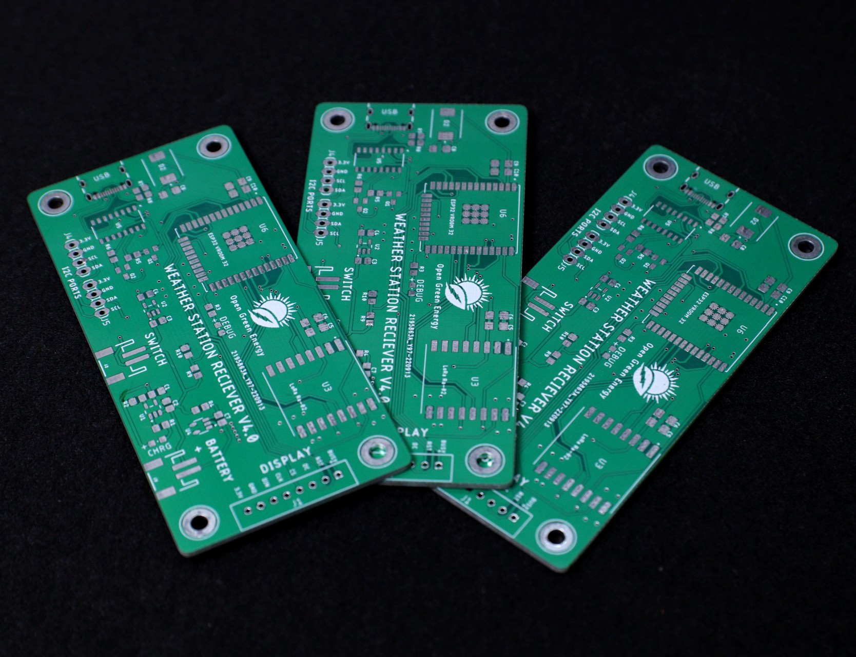
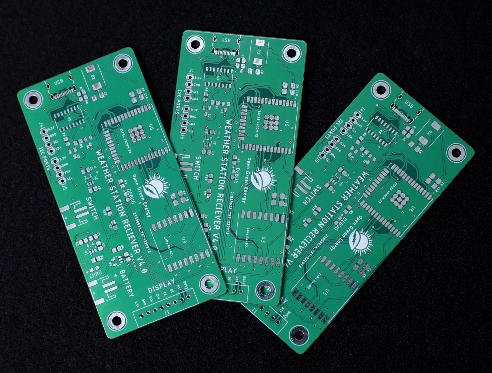
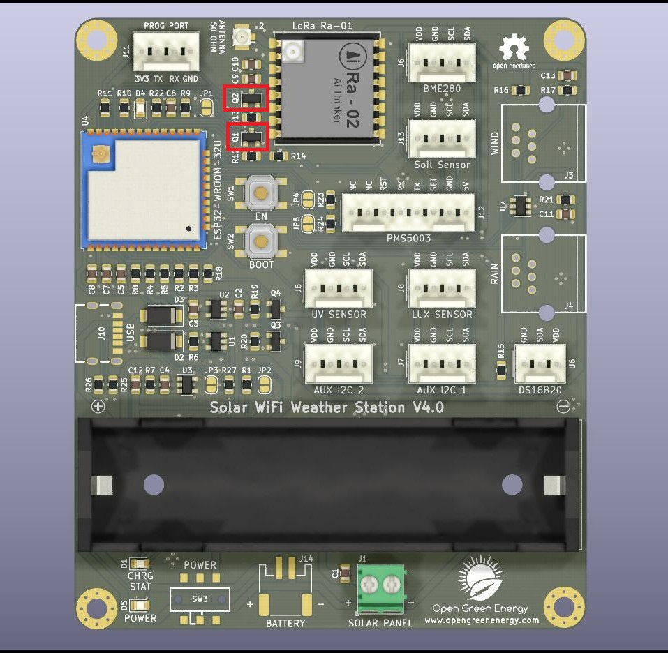
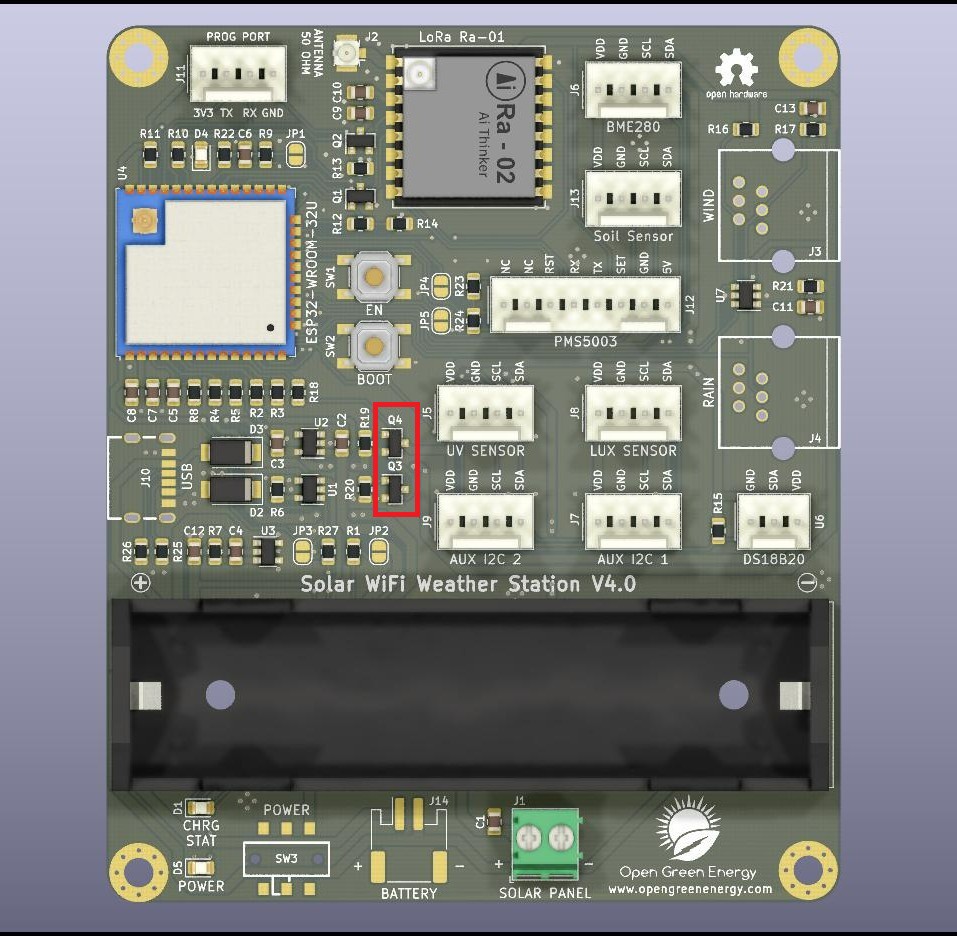
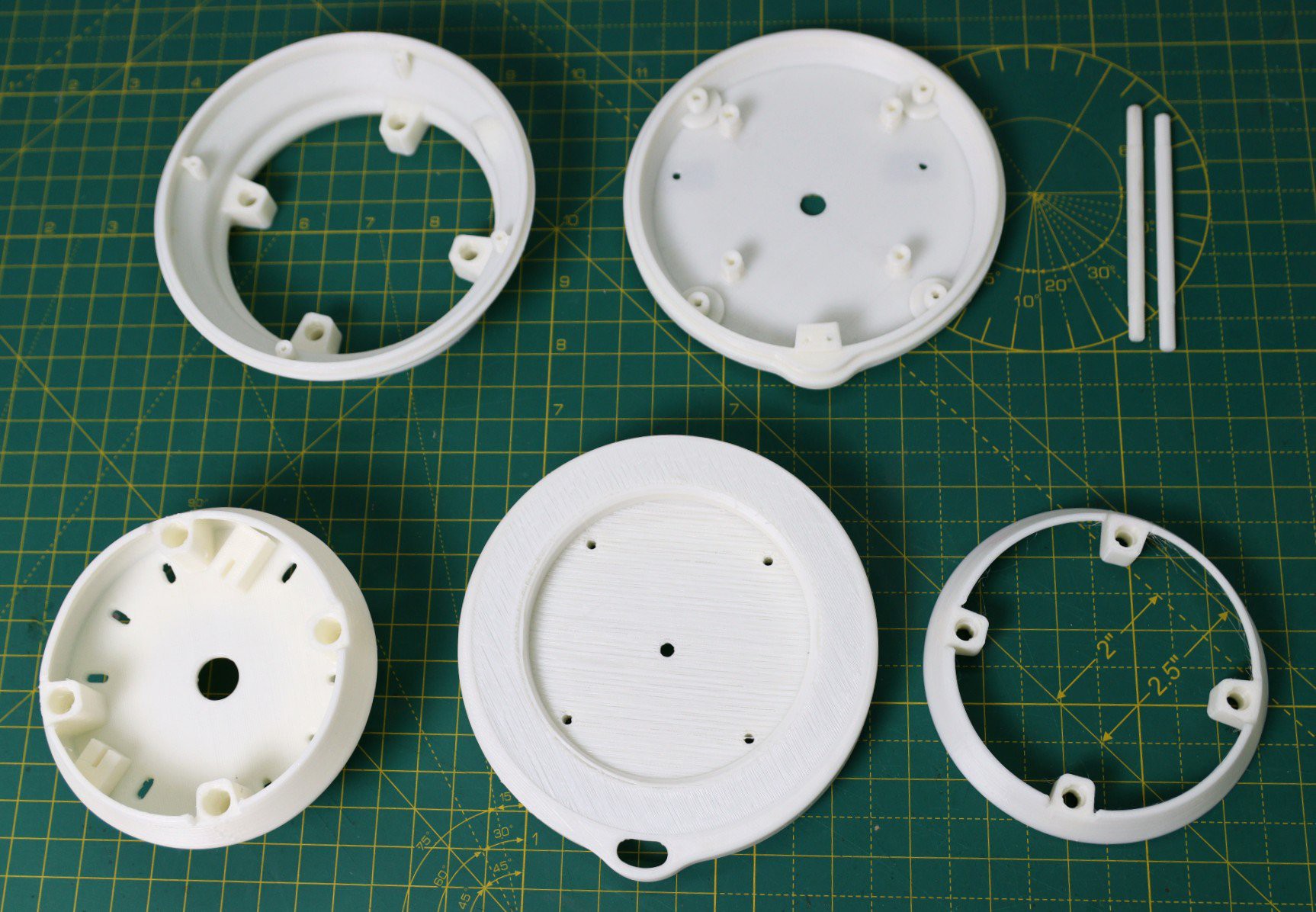
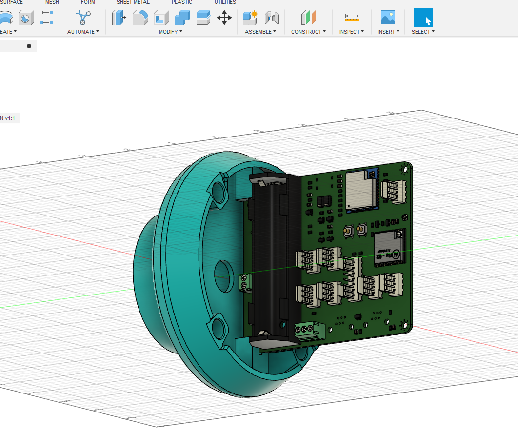
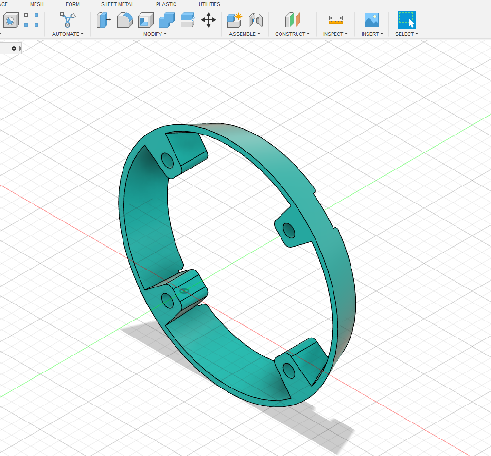
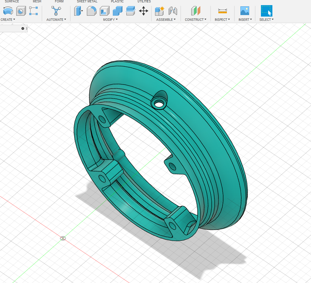
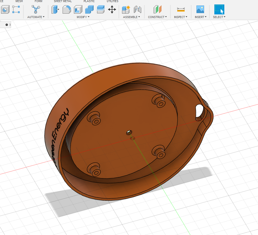
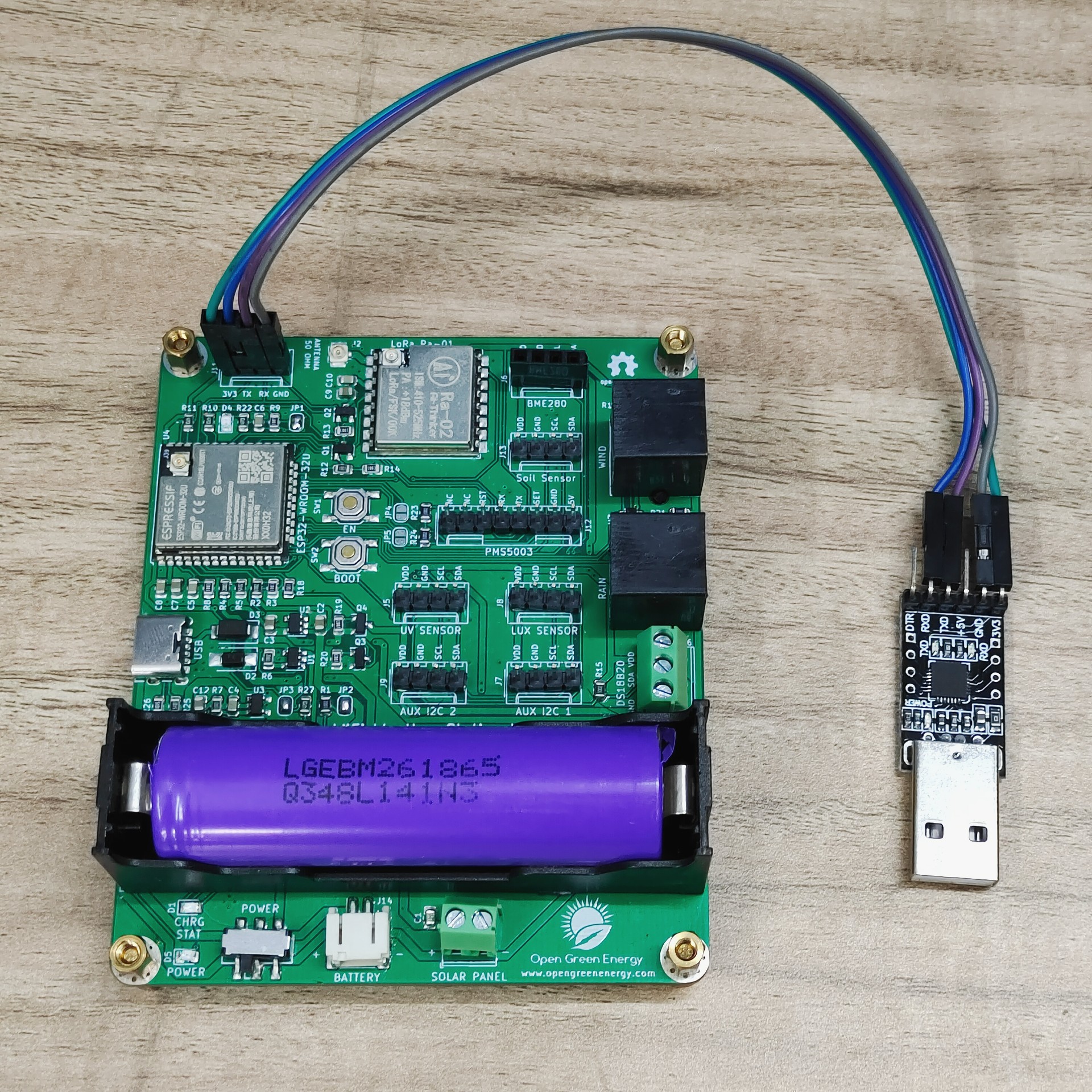
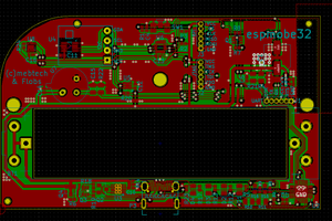
I have designed a customized PCB for this project. It is designed in such a way that you can conveniently integrate different combinations of sensors according to your actual application needs.

Why a Weather Station?

Imagine you are residing in a place that is far away from the meteorological department. In such a case, the weather predictions you get may not be the most precise. This is where home weather stations become more advantageous. This small weather station can provide accurate data regarding the weather parameters of where you live.

Today, data on localized weather, known as microclimates, is the new frontier for more precise and accurate weather forecasting. As a result, the collection of weather data is becoming increasingly smaller and gridded.

Applications:

The applications of this type of small portable weather station are vast in the area of smart agriculture, smart city, solar power plants, construction site, etc.


Support me On Patreon:

If you enjoy my work here on Instructables, consider joining my Patreon, it will be a great help for me to make more interesting projects in the future.

Patreon Link:https://www.patreon.com/opengreenenergy

x-zip-compressed - 1.75 kB - 02/27/2023 at 18:01

Download

sheet - 17.30 kB - 02/27/2023 at 18:01

Download

x-zip-compressed - 317.74 kB - 02/27/2023 at 18:01

Download

Adobe Portable Document Format - 34.08 kB - 09/12/2022 at 19:59

Preview
Download

Adobe Portable Document Format - 80.99 kB - 09/01/2022 at 02:47

Preview
Download

View all 6 files

  • 1 × 18650 Battery Holder
  • 6 × Capacitor_SMD_0805 -10uF C1, C2, C3, C7, C9, C12
  • 5 × Capacitor_SMD_0805 -0.1uF C4, C5, C6, C8, C10
  • 2 × Capacitor_SMD_0805 -1uF C11, C13
  • 3 × LED_SMD _0805 - Green , Blue , Red CHRG STAT, DEBUG, POWER

View all 32 components

  • Published New Software

    Open Green Energy11/10/2022 at 08:49 1 comment

    Published a new version of code with implementing MQTT. The software is developed by my friend Jame Hughes.

    You may find the details in the following link.

    https://jameshughes.atlassian.net/wiki/spaces/WSVL/pages/1963360257/Software+Notes

    Released a stable version of the software for both the Base Station and Receiver Node. You can find it on Jame's GitHub Page.

    1. Download the Code for Transmitter ( Base Station ) here
    2. Download the Code for the Receiver Node here.


    Your feedback is useful for us, please suggest us for improvement.

  • Designed an 3D printed Enclosure for Receiver

    Open Green Energy09/27/2022 at 17:58 0 comments

    I have designed an enclosure in Fusion360 for the weather station receiver node. It includes a 4.2" e-paper display and my customized receiver PCB board. I have also included antennas for both the ESP32 and LoRa modules. 

    The pictures of my designs are attached below:

  • Receiver PCB Board Assembled

    Open Green Energy09/27/2022 at 17:41 1 comment

    Today I assembled the PCB board, but the USB port was not soldered due to the unavailability of stock. As the USB port is not soldered, not able to upload the program now, Place the order for the USB-C port, it will be delivered by this weekend, I will update the results then.

    Placed the components using Solder Paste:


    Assembled PCB:

  • Receiver Node PCB Arrived

    Open Green Energy09/26/2022 at 19:02 1 comment

    Today I received the PCB for the receiver board from PCBWay. The PCB quality is extremely good. I am excited to assemble it and see the results. Stay tuned, I will update the results soon.

     The pictures of the new PCBs are attached below. 

  • Ultra Low Power Consumption

    Open Green Energy09/22/2022 at 14:48 0 comments

    The heart of our Weather Station is an ESP32 SOC, a power-hungry chip. When the project is powered by a plug-in wall, you tend not to care too much about power consumption. But if you are going to power your project with batteries, every mA counts.

    Our objective is to run the device by using a 18650 Li-Ion battery. To run the ESP32 by using a battery, we have to lower the power consumption. The power consumption can be reduced in the following ways:

    1. Software Optimization 

    2. Hardware Optimization

    Software Optimization:

    Using Deep Sleep Mode which is the most power-efficient option for the ESP chip. It allows to put the ESP32 into hibernation and saves the battery. You can wake up the ESP at regular intervals to make measurements and publish them.

     Hardware Optimization:

    The power-consuming components in the PCB are LEDs,  ESP32, LoRa, and Sensors. The ESP32 power consumption can be minimized by software optimization. However, we can reduce the power consumption of all other components by optimizing hardware design. 

    I have considered the following in my hardware design to reduce the power consumption

    A. LED jumpers: 

    You can enable/disable all the 3 LEDs ( DEBUG, CHRG, and POWER  ) used in the PCB board by using the jumpers JP1, JP2 and JP3. The default state is in disable condition, but if you need them, bridge the Jumpers by applying solder.

    B. Power Switch for LoRa:

    I have added a power switch circuit by using a MOSFET ( Q2)  and transistor ( Q1 ) for complete shut down of the LoRa module during the sleep mode. The ESP32 GPIO pin 16 is used to control this power switch.

    C. Power Switch for Sensors:

    I have added a power switch circuit by using a MOSFET ( Q3)  and transistor ( Q4 ) for the complete shutdown of all the sensors during sleep mode ( when no sensor data is to be sent). The ESP32 GPIO pin 26 is used to control this power switch.

  • 3D printed the Enclosure

    Open Green Energy09/21/2022 at 06:55 0 comments

    I used my Creality 3D printer and 1.75 mm white PLA filament to print the parts. I will recommend using ABS or PTEG filament instead of using PLA. I have used PLA just for the quick test as I don't have ABS or PTEG filament in my stock.

    My print settings are:

    Print Speed : 60 mm/s

    Layer Height: 0.3mm

    Fill Density: 25%

    Extruder Temperature: 210 deg C

    Bed Temp: 65 deg C

    I have printed the files successfully but there are minor issues in the fitting of a few parts like M4 rods, and middle cover, and the top cover. I will adjust it soon. 

    I have also checked the solar panel fitting, it works as expected.

  • Designed a 3D printed Stevenson Screen

    Open Green Energy09/20/2022 at 19:00 0 comments

    The ideal enclosure for keeping the weather sensors is the Stevenson Screen. A Stevenson screen is an enclosure to shield meteorological sensors against precipitation and direct heat radiation from outside sources, while still allowing air to circulate freely around them.

    I have designed a 3D printed Stevenson screen to keep the weather sensors and PCB board. The enclosure has the following parts:

    1. Base part

    2. 4 x Middle Rings

    3. Middle Cover  ( Separate the Solar panel from the  PCB chamber )

    4. Top Cover ( above which a 130 mm circular solar panel will be mounted )

    The whole idea is to stack all the above parts one above the other so that the inside chamber will be well-ventilated from the outside. 

    The above parts will be assembled by using 4x M4 rods, it can also be 3D printed.

    Full Enclosure: 


    Base Part:


    Middle Rings: ( Required 4 Numbers ) 

    Middle Cover:


    Top Cover:

  • Prototype for Receiver Board

    Open Green Energy09/20/2022 at 06:56 1 comment

    I have made a prototype board to check the main feature of the above circuit on a perforated board. I tested the board with a BME280 sensor hook up to the Sender Board, and finally received the sensor data successfully. 

    Here are some pictures of my prototype test

    Interfacing with 4.2" e-paper Display:

    I have tested the prototype board with the same pin assignment as I have done in the above schematic diagram. My idea is to make a customized display with all the sensor data and some icons and graphs.

    I found a beautiful code on GitHub with a similar thought, but the author uses weather data from  Open Weather Map instead of actual sensor data. My plan is to modify the existing code to incorporate the sensor data and retain the weather icons and graphs. 

    I just uploaded the example code to my receiver board, and it works satisfactorily. No, my challenge is to tweak the existing code to achieve the desired goal.

  • Successfully Uploaded the Test Code to Transmitter Board

    Open Green Energy09/20/2022 at 06:46 0 comments

    After assembling the transmitter PCB board, I connected my USB to the TTL UART programmer to the programming port. The connections are as follows:

    Programmer -----> PCB

    3V3 ----> 3V3

    Tx----> Rx

    Rx----> Tx

    GND---> GND

    After connecting the programmer to the PCB board, I successfully uploaded the test code. The board is working as expected but I have to press the EN switch to start the execution. This is required only once after uploading the code.

    I have tested the following:

    1. All the I2C ports are working

    2. Wind and Rain Sensors Ports working

    3.  DS18B20 port is working

    4. Battery charging through solar panel and USB port is working

    5. LoRa module is working as expected but needs an external antenna

    6. Battery and Solar Panel Voltage monitoring working

    Test Code is attached below:

    //======================================================================================//
    // //
    // Solar WiFi Weather Station V4.0 Firmware //
    // //
    // Developed by Debasish Dutta, Last Update: 14.09.2022 //
    // //
    //======================================================================================//
    #include <SPI.h>
    #include <LoRa.h>
    #include <BME280I2C.h>
    #include "Adafruit_SI1145.h"
    #include <BH1750.h>
    #include <DallasTemperature.h>
    #include <OneWire.h>
    #include "Wire.h"
    //#include "esp_deep_sleep.h" //Library needed for ESP32 Sleep Functions
    #include "time.h"
    #include <sys/time.h>                   /* gettimeofday(), settimeofday() */
    //=================== Pin assignment definitions ==========================================
    
    //define the pins used by the LoRa transceiver module
    #define SCK  18                 
    #define MISO 19
    #define MOSI 23
    #define SS   15
    #define RST  17
    #define DIO0 13
    
    // define sensors pin
    #define WIND_SPD_PIN        26  //reed switch based anemometer count
    #define RAIN_PIN            25  //reed switch based tick counter on tip bucket
    #define WIND_DIR_PIN        35  //variable voltage divider output based on varying R network with reed switches
    #define SOL_VOLT_PIN        36  //voltage divider for Solar panel monitor
    #define BAT_VOLT_PIN        39  //voltage divider for battery monitor
    #define TEMP_PIN            15  // DS18B20 hooked up to GPIO pin 15
    //#define LED_PIN           14  //Diagnostics using built-in LED
    #define LORA_PWR            16  // Power Switch to complete shutdown of LoRa module
    #define SENSOR_PWR          26  // Power Switch to complete shutdown of all the sensors
    
    #define batteryCalFactor 0.00263361
    #define SolarCalFactor   0.00577798
    
    //=======================================================================================
    
    //433E6 for Asia
    //866E6 for Europe
    //915E6 for North America
    #define BAND 433E6
    
    //=======================================================================================
    
    BME280I2C bme;
    Adafruit_SI1145 uv = Adafruit_SI1145();
    BH1750 lightMeter(0x23);
    OneWire oneWire(TEMP_PIN);
    DallasTemperature sensors(&oneWire);
    
    //=========================Declaring Variables and Constants ==========================
    
    // Variables used in reading temp,pressure and humidity (BME280)
    float temperature, humidity, pressure;
    // Variables used in reading UV Index (Si1145)
    float UVindex;
    // Variables used in reading Lux Level( BH1750 )
    float lux;
    // Variables used in reading battery and solar panel voltage
    float batteryVolt;
    float SolarVolt;
    // Variables used in calculating the windspeed
    volatile unsigned long timeSinceLastTick = 0;
    volatile unsigned long lastTick = 0;
    float windSpeed;
    // Variables used in calculating the wind direction
    int vin;
    String windDir = "";
    // Variables used for sending LoRa message
    String LoRaMessage;
    
    // Variables and constants used in tracking rainfall
    #define S_IN_DAY 86400
    #define S_IN_HR 3600
    #define NO_RAIN_SAMPLES 500
    RTC_DATA_ATTR volatile long rainTickList[NO_RAIN_SAMPLES];
    RTC_DATA_ATTR volatile int rainTickIndex = 0;
    RTC_DATA_ATTR volatile int rainTicks = 0;
    RTC_DATA_ATTR int rainLastDay = 0;
    RTC_DATA_ATTR int rainLastHour = 0;
    RTC_DATA_ATTR int rainLastHourStart = 0;
    RTC_DATA_ATTR int rainLastDayStart = 0;
    
    long secsClock = 0;
    //=========================Deep...
    Read more »

  • PCB for Transmitter Board

    Open Green Energy09/20/2022 at 06:10 0 comments

    I have received the PCB from my transmitter board from PCBWay. Then I soldered the components using my own hot plate. The final look is really awesome, attaching a few pictures for the same.

    The main features of the PCB are

    1. 2 Battery Options: Either 18650 battery directly into the slot or LiPo battery through the battery JST connector

    2. Solar charging port: " SOLAR PANEL "  screw terminal

    3. USB-C charging port - USB-C is given for quicker charging of the battery in case of low sunlight for a long time.

    4. 6 x I2C ports for hooking up a variety of sensors

    5. 2x RJ11 ports for connecting the Wind and Rain Sensor

    6. Additional port for Air Quality Sensor ( PMS5003 )

    7. Screw terminal to connect the DS18B20 temperature probe 

    8. Programming port for uploading the sketch by using a UART serial programmer

View all 17 project logs

Enjoy this project?

Share

Discussions

pierrewirth1 wrote 05/31/2023 at 19:19 point

Bonjour,

je ne retrouve nulle part les gerber du récepteur ??

Mrci pour la réponse

  Are you sure? yes | no

murraythegoz wrote 03/16/2023 at 16:11 point

Do you plan to have the pre-assembled pcb avail on PCBWAY bazaar as you did for version 2.0 and 3.0?

My soldering skills are not so good and never played with hot plate soldering.

Thanks in advance

  Are you sure? yes | no

soulifa wrote 03/05/2023 at 20:59 point

Thanks for posting the receiver files @Keshka  much appreciated! I have tried to upload the files with PCBway. aisler.net and JLCPCB and there are always issues with either missing placement files or missing BOM components. Did anyone manage to order the boards. Are they working as intended`?

  Are you sure? yes | no

Keshka wrote 02/16/2023 at 19:18 point

Weather station receiver

An add on for opengreenenergy weather station project. Debasish Dutta had provided the pc board for the weather station transmitter but no receiver board so I created one and added the ability to solar power it as well so it could be placed on a window sill.

https://www.pcbway.com/project/shareproject/Weather_station_receiver_f389ad78.html

  Are you sure? yes | no

Keshka wrote 02/12/2023 at 18:12 point

Nice project Debasish, we still need the pc board for the receiver to complete this project. Have not seen any activity from you in several months. Hoping you will post the final details and upload the receiver board to PCBway.

  Are you sure? yes | no

soulifa wrote 02/06/2023 at 22:37 point

Great project, very well documented! I was about to order the weather station board from PCB Way when I realised the gerber files of the receiver are missing.  @Debasish Dutta  are you planning to include them? Thank you!

  Are you sure? yes | no

zfsnotification wrote 02/02/2023 at 07:45 point

When will PCBs be available?

  Are you sure? yes | no

jakeoldboy wrote 12/02/2022 at 18:34 point

Debasish: what is your recommended ordering choices for ordering the pre-assembled PCB board for your new Solar Weatherstation v4.0? And, what is the preassembled PCB board from PCBWay cost? Lastly, I like the Loran communication that’s built-in; however, I’ve seen your comments that Wifi communication is built into the board? Is that true? I prefer using wifi at first. Thanks, John Pingel

  Are you sure? yes | no

davidefa wrote 10/31/2022 at 21:32 point

@nerdu

If you want add meshing capabilities to this lora project you can use the radio head libraries ( https://www.airspayce.com/mikem/arduino/RadioHead/ ).

Not difficult to use. I'm writing an howto at this address: https://www.hackster.io/davidefa/esp32-lora-mesh-1-the-basics-3a0920 ( published only first part  )

  Are you sure? yes | no

bodyfarmer wrote 10/24/2022 at 11:03 point

The middle cover part 3D file is missing. Would you mind adding it to the files?

  Are you sure? yes | no

Werdis80 wrote 06/16/2023 at 21:40 point

there is here www.thingiverse.com/thing:5555455

  Are you sure? yes | no

davidefa wrote 10/18/2022 at 06:48 point

I see you only posted a test code for the transmitter, could you kindly post a test code for the receiver ( I understand it is a work in progress, but a simple sketch that receive the data transmitted an prints the result on the debug port could be enough ).

P.S.

forgot to add: nice project

P.P.S.

An addition ( for v5.0 station ): an sd interface for storing data locally on the receiver

P.P.P.S.

On github the software in development: https://github.com/jhughes1010/weather_v4_lora

  Are you sure? yes | no

Leeward Bound wrote 09/30/2022 at 19:32 point

This is a great project, and would solve a lot of my needs, but I don't really have the expertise to build and assemble the parts list myself - are there plans to eventually sell fully assembled / finished units?

  Are you sure? yes | no

bortek wrote 09/26/2022 at 06:44 point

what is the purpose of the external and internal temperature sensors and what are the differences between them? 

  Are you sure? yes | no

Open Green Energy wrote 09/26/2022 at 19:34 point

The outer temperature probe is more accurate compared to the BME280. It's for backup only. 

  Are you sure? yes | no

bortek wrote 09/27/2022 at 04:40 point

Where is the outer one designed to be placed? Anywhere outside ofcthe stephenson shield? 

I imagine internal one is integrated on the board, is it so? In that case it will bot have accurate measurements since it will be saturated byvthe heat radiated from the board. 

  Are you sure? yes | no

david.windsor wrote 09/25/2022 at 22:38 point

Get everything non-white off the Stevenson screen, it will mess up everything temperature related when hit by direct sunlight. I knew a climate researcher who had to scrap 2 years of data because he used BLACK silicone to waterproof a dozen temperature sensors. Threw the daytime readings off by ~2°C.

  Are you sure? yes | no

Open Green Energy wrote 09/26/2022 at 04:10 point

I have used all the parts in white only.

The colour is just in 3D design file to distinguish between the different parts.

  Are you sure? yes | no

naivetinkerer wrote 09/22/2022 at 23:04 point

Hey Dabasish, do you plan on putting the PCB designs up on your PCBWay page? Nice work!

  Are you sure? yes | no

Open Green Energy wrote 09/23/2022 at 09:34 point

Hi, now I have to correct some minor issues in the PCB. Once it is finalized, I will share it on PCBWay too.

  Are you sure? yes | no

nerdu wrote 09/20/2022 at 07:54 point

is possible add mesh to this device? lora, wifi etc. 

  Are you sure? yes | no

Open Green Energy wrote 09/20/2022 at 14:42 point

LoRa and WiFi is already included in it

  Are you sure? yes | no

tywy wrote 09/23/2022 at 08:42 point

lora != mesh lora look https://meshtastic.org/

wifi != wifi mesh 

  Are you sure? yes | no

nerdu wrote 09/23/2022 at 13:34 point

yes but this is not mesh lora. other device not send data trought other device to router/center

  Are you sure? yes | no

James Hughes wrote 02/05/2023 at 11:18 point

Not planning on supporting mesh. I've got a LoRaWAN gateway I'll be forking the project for as I want to experiment in that direction.

  Are you sure? yes | no

Similar Projects

Does this project spark your interest?

Become a member to follow this project and never miss any updates