 Nicolas REIMEN
All right. One more retrobrew TTL CPU.
What did make me want to do this kind of thing? Really, I always wanted to do it. As a kid (12-13), I played with microprocessors in the 1980s (6809 mostly). Had a C64 too. But even back then I wondered about these little 14 pin cockroaches and asked myself what it would take to build an entire computer out of them. Now I am over 50 and have quite a lot of time on my hands so I told myself 3 months ago or so that it was time to look seriously into starting my own TTL CPU retrobrew project (as they are called now)
What am I trying to achieve?
A Retrobrew project is a work of art. The goal is aesthetic, not practical. It has to look right and feel right. Here are the aesthetic canons I intend to follow:
1. Classicism
I aim for a classic late 70s look and feel, like a VAX-11/780 or a Xerox Alto, In particular:
- PCBs are green (not red or blue)
- Components are through-hole, not SMD
- LEDs are round 5mm, red, green or amber. No bar-graph modules. No rectangular shapes. Not even 3mm round ones. Of course, no RGB LEDs or other monstrosities.
- Each LED has its own current-limiting resistor. No resistor arrays.
- C language is the basic system programming language. No Forth or other weird stuff.
Finally, a retrobrew project needs to be seen. So no enclosures. Just PCBs on a mounting support.
2. Baroque
Within these classical guidelines, I feel an urge for the baroque, the outlandish, the mildly outrageous. This urge lead me to the following options:
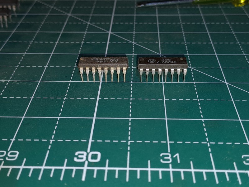
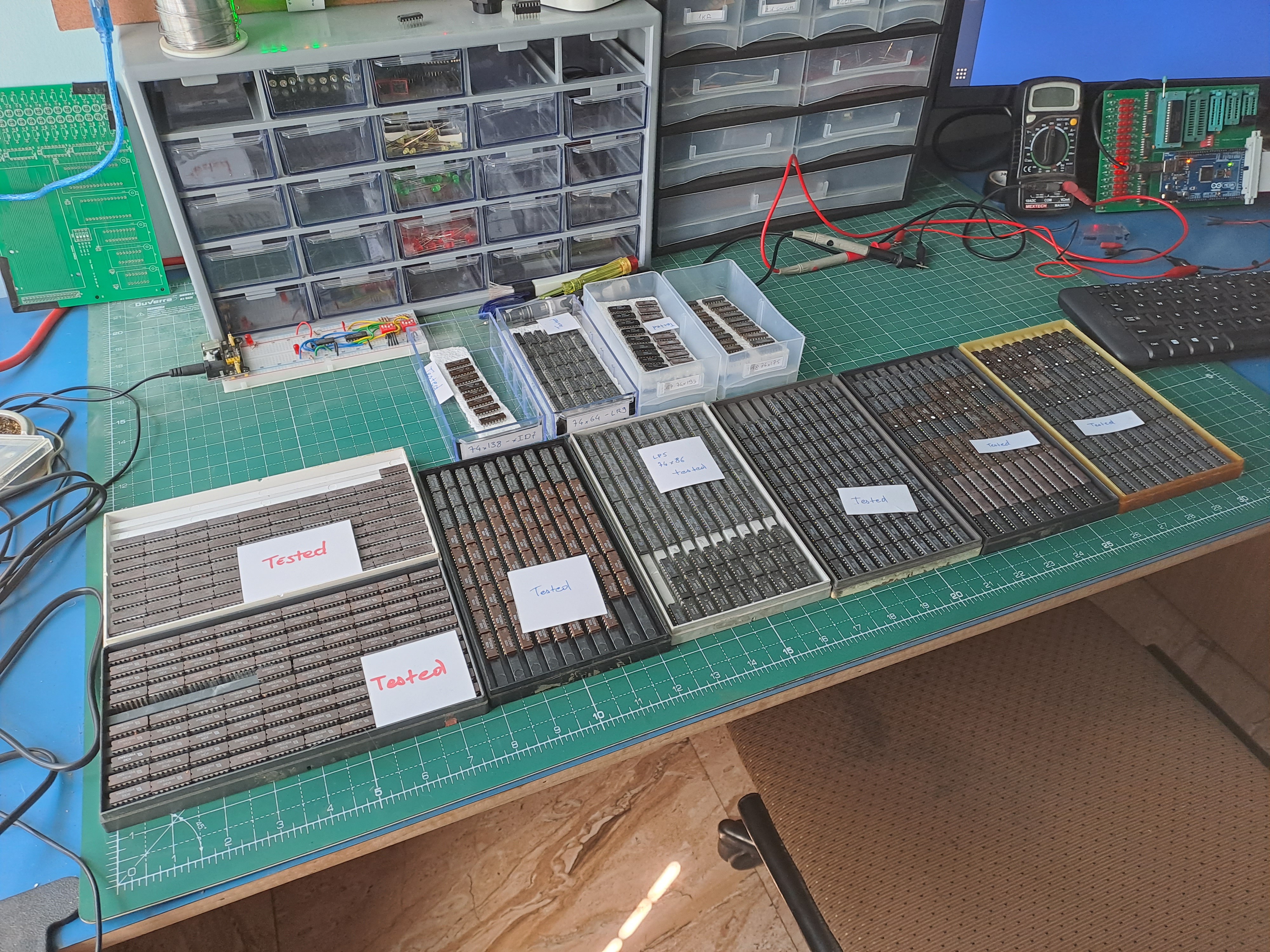
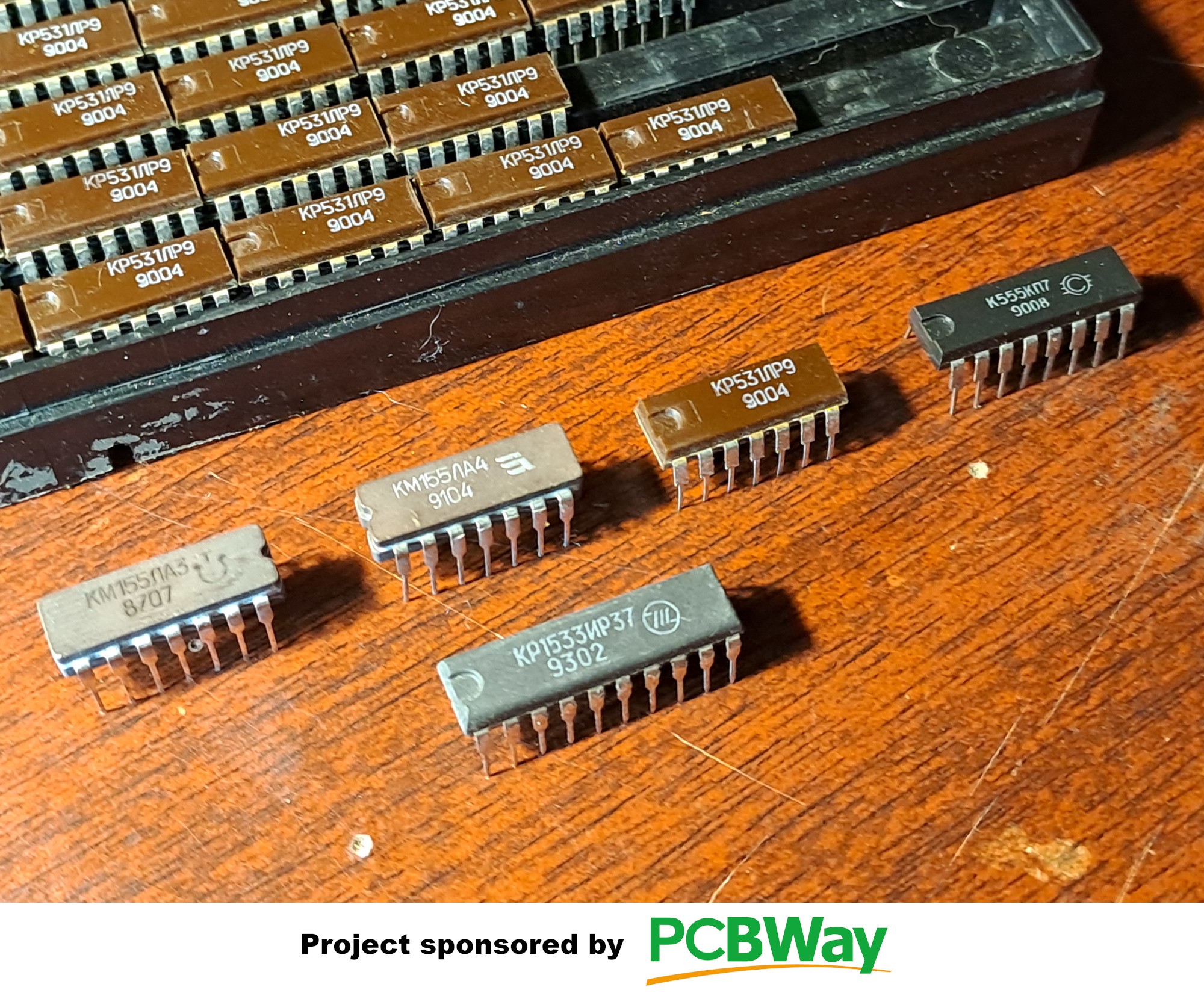
- Use of old soviet TTL chips. Early on in the 70s, the USSR started cloning the 74 series chips from TI and other US manufacturers. Some of these clones are still produced and much new old stock is still floating around. I have found a number of reliable sources on E-bay and will try to source all the chips I need from them. Soviet clone chips add a touch of John Le Carré flavor to the project and even (to me at least) a hint of post-apocalyptic atmosphere.
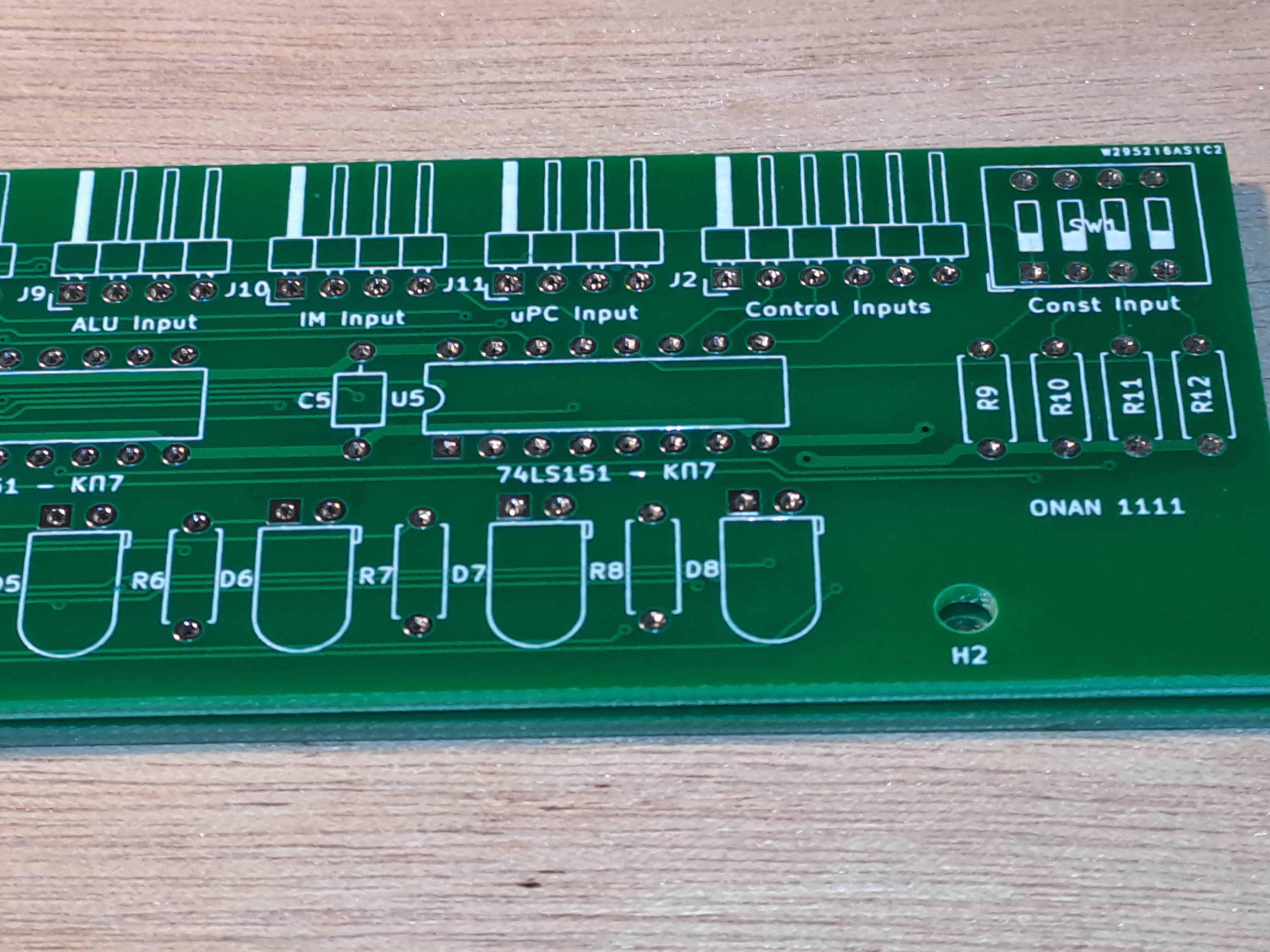
- Only microprogramming. The ONAN 1111 CPU will have no ISA. All software tasks will be handled at the microprogram level. That way, all instructions are by construction 1 clock cycle long. The C compiler will directly output microprogram binary. ONAN 1111 will be a single-task machine, in the spirit of Apollo's AGC, for example. Of course, this task will itself include a number of features (to be disclosed more fully later).
- 20 bit length. I have heard of 36, 48, 12 or 24 bit lengths, but not 20. Why? 20 bits has a number of (aesthetic) advantages:
- 2^20 is in the neighborhood of 1 million, a nice round number. Both address and data buses will be 20 bit wide: a total memory of 1 million 20 bit words.
- 20 bits is enough to hold all UNICODE characters within a word. A character string on ONAN 1111 will be a string of 20 bit words. In C terms: char = short = int = 20 bit.
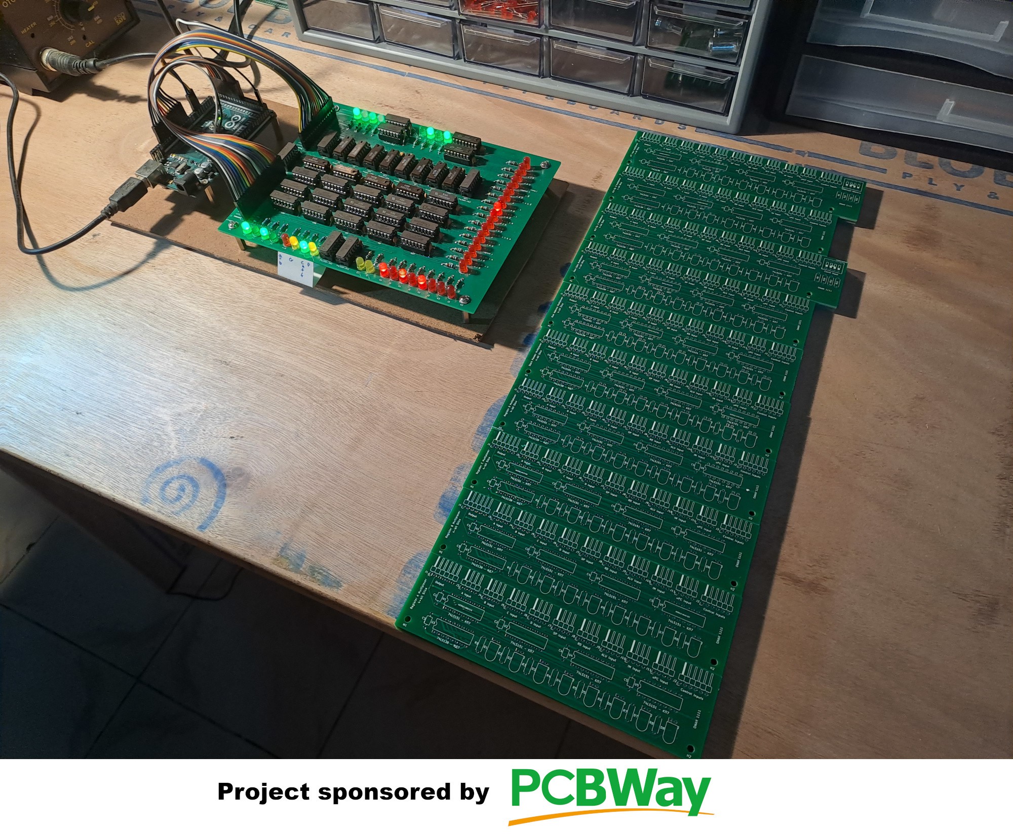
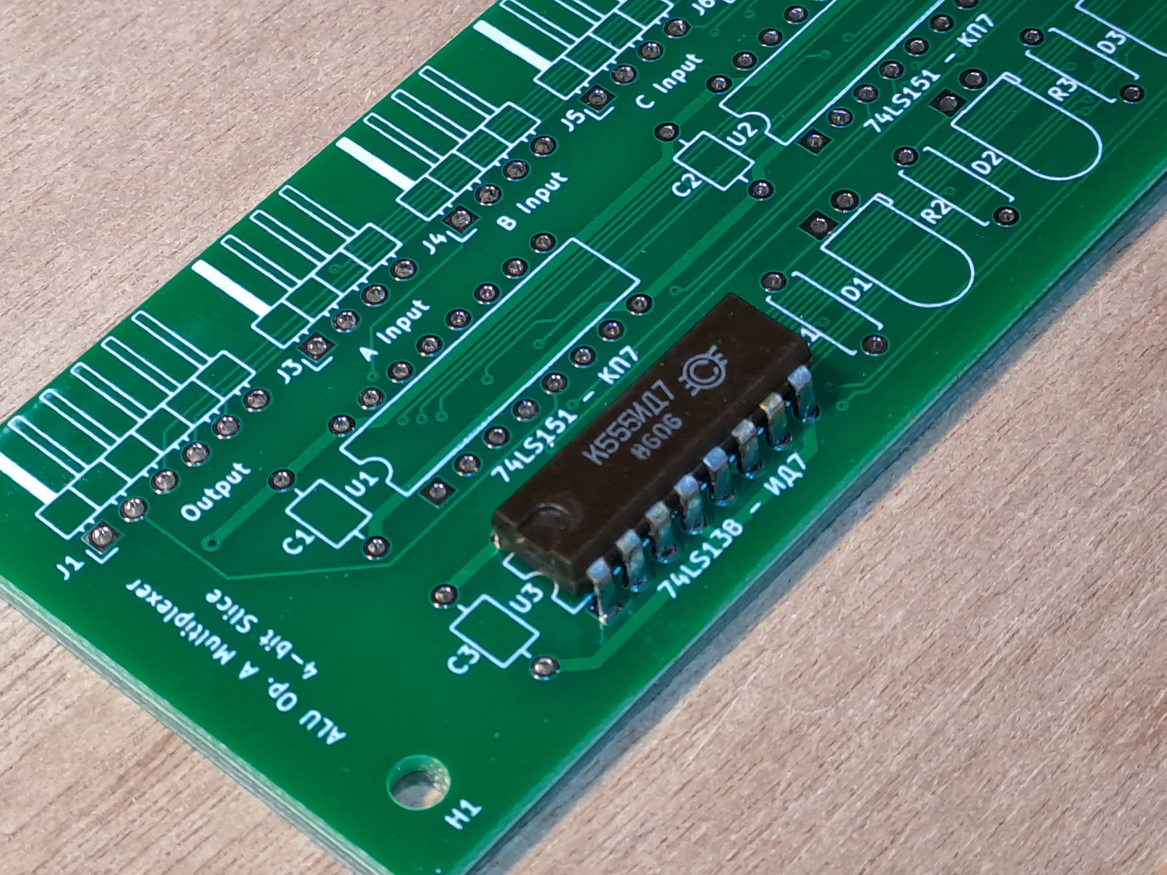
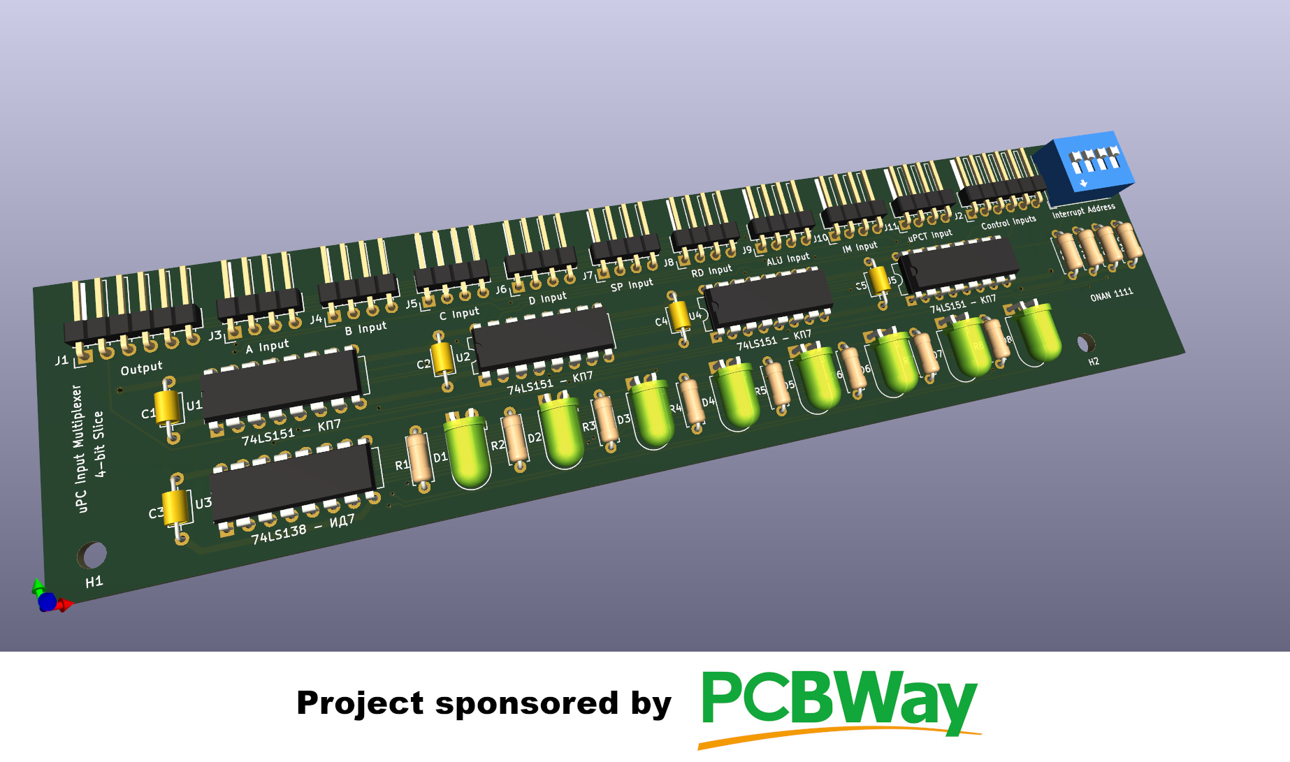
- 20 is 4*5. Since almost all online PCB manufacturer require a minimum quantity of 5 per PCB run, this will make it possible to build ONAN 1111 in 4 bit wide slices, each component having 5 slices. The PCB in the picture above shows a 4-bit ALU slice (a reimplementation of the 74x181)
- Crossbar switch. Most CPUs have 1 to 3 internal buses to carry data between the different component. ONAN 1111 will have an 8-way crossbar switch instead. As a result all possible transfers between the 3 registers, the SP, the uPC, the ALU and the Ram address/data buses will be possible within a clock cycle. The crossbar switch alone will require 180 К555КП7 (74x151 clone) chips. Luxury has its uses in art.


 Marcel van Kervinck
 Dave's Dev Lab
 Andre Baptista
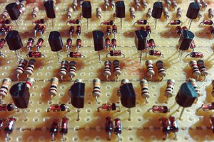
 matseng
Amazing project! Looking forward to dig into all the project logs and learn a lot I am sure. Btw, check out my microcoded designs (including a compiler), and a serial-CPU using 16*16 crossbar switch :-)