Peter Lyons
Thanks to PCBWay for providing PCB Manufacturing services at no cost for this project!
0%
0%
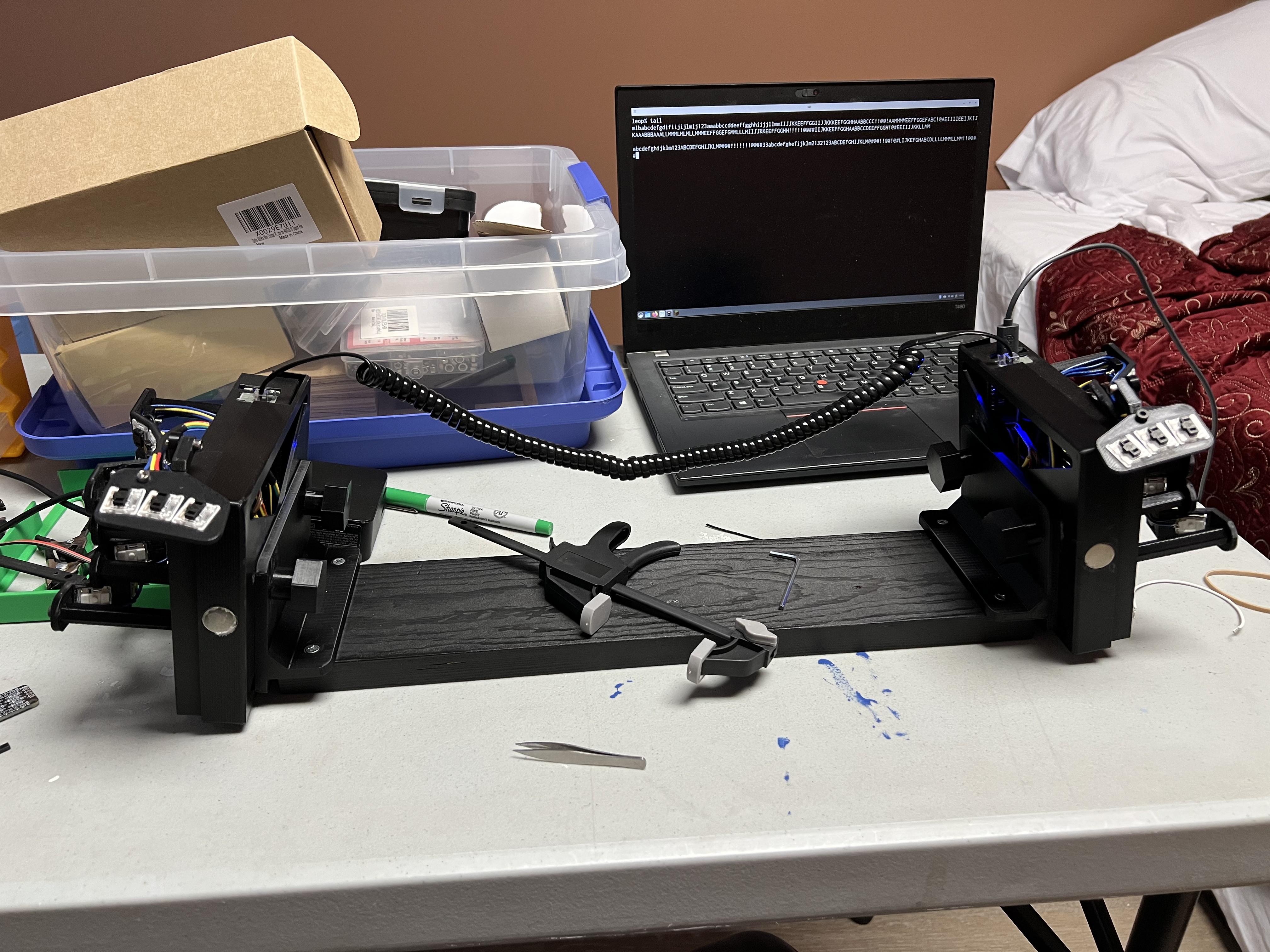
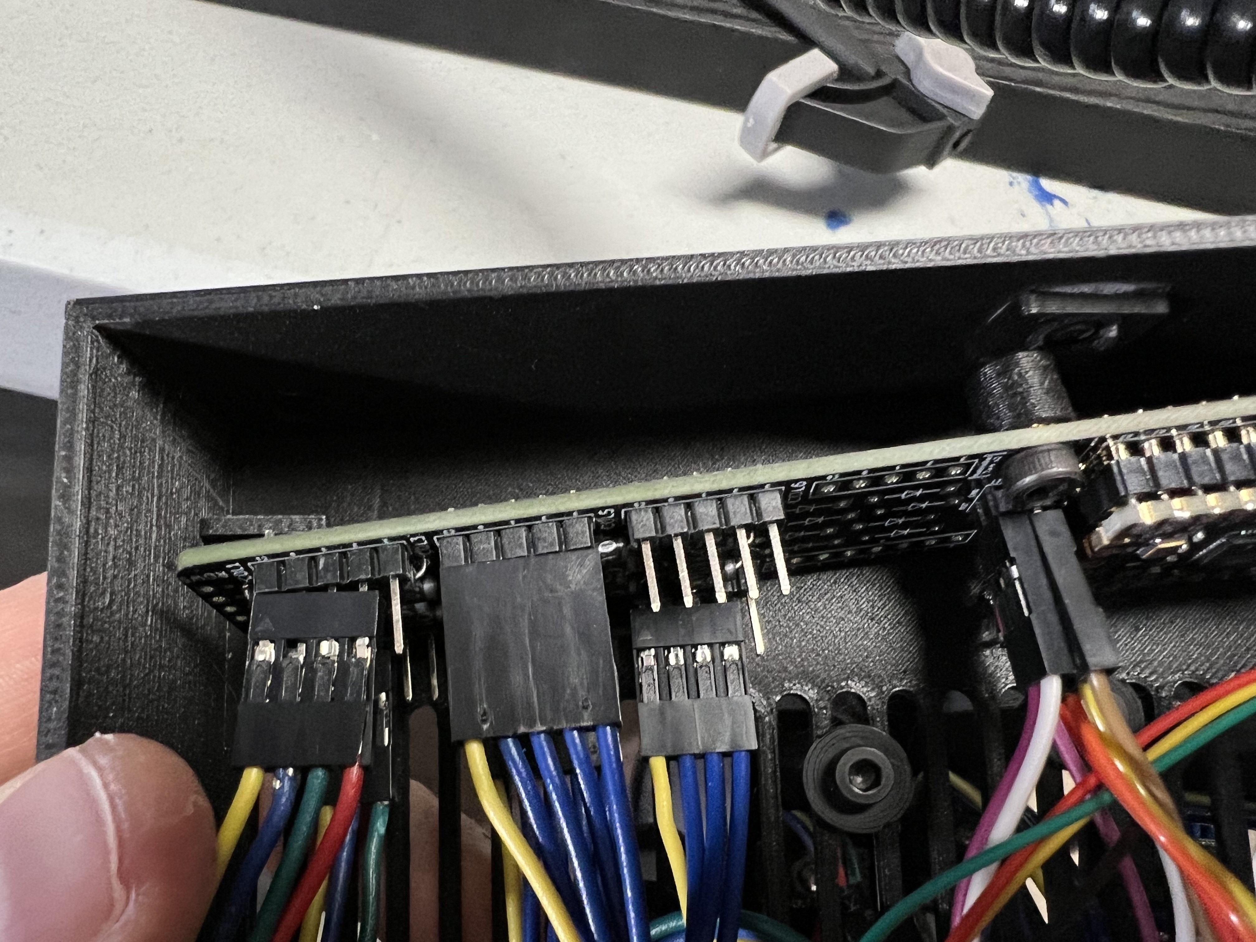
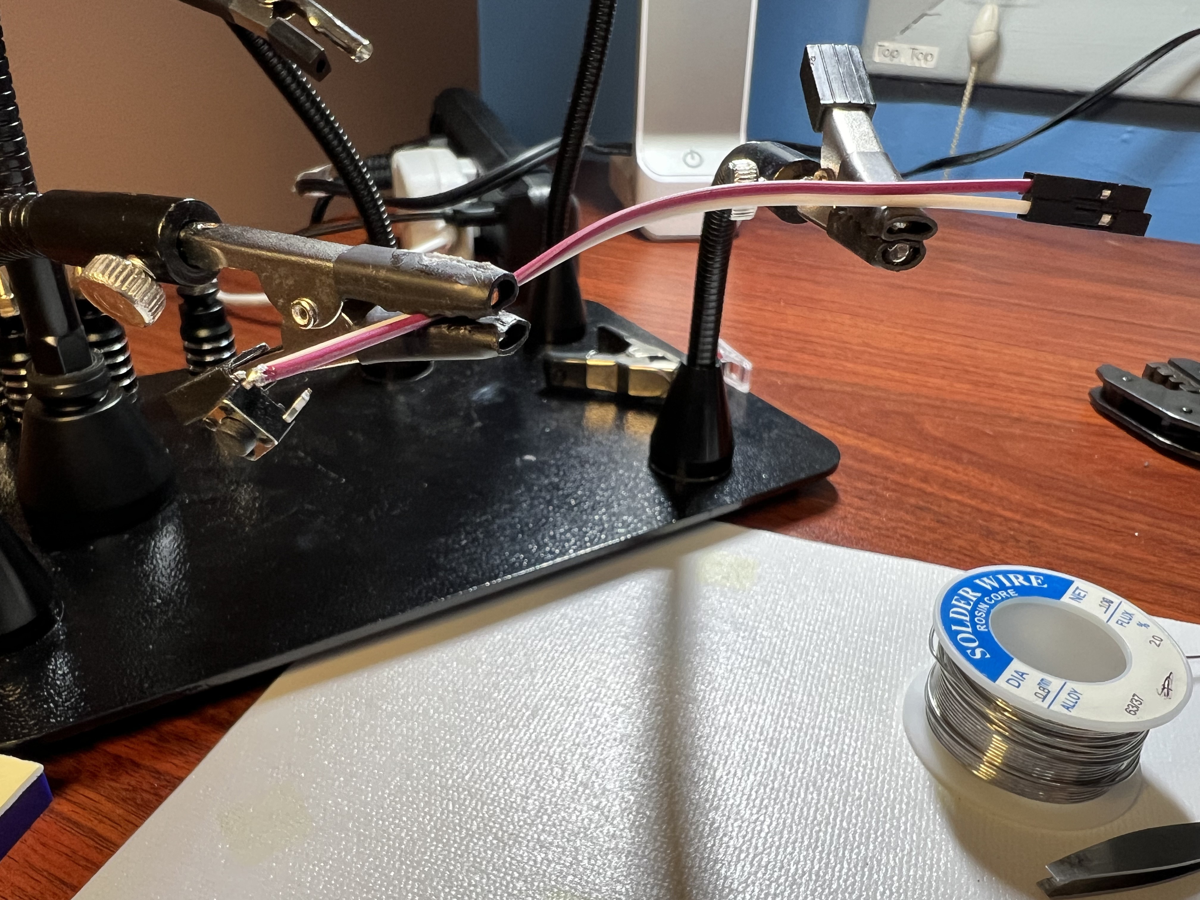
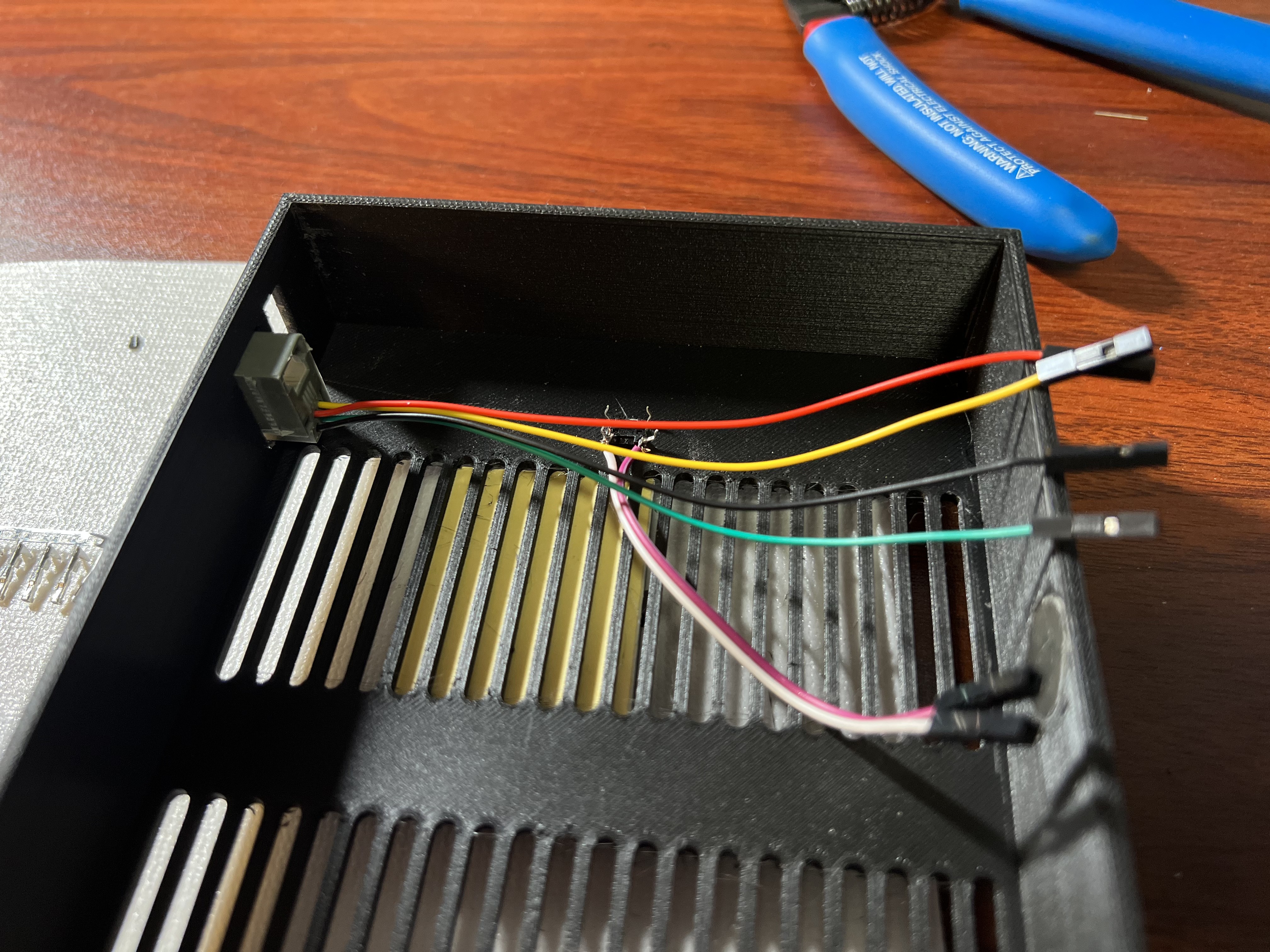
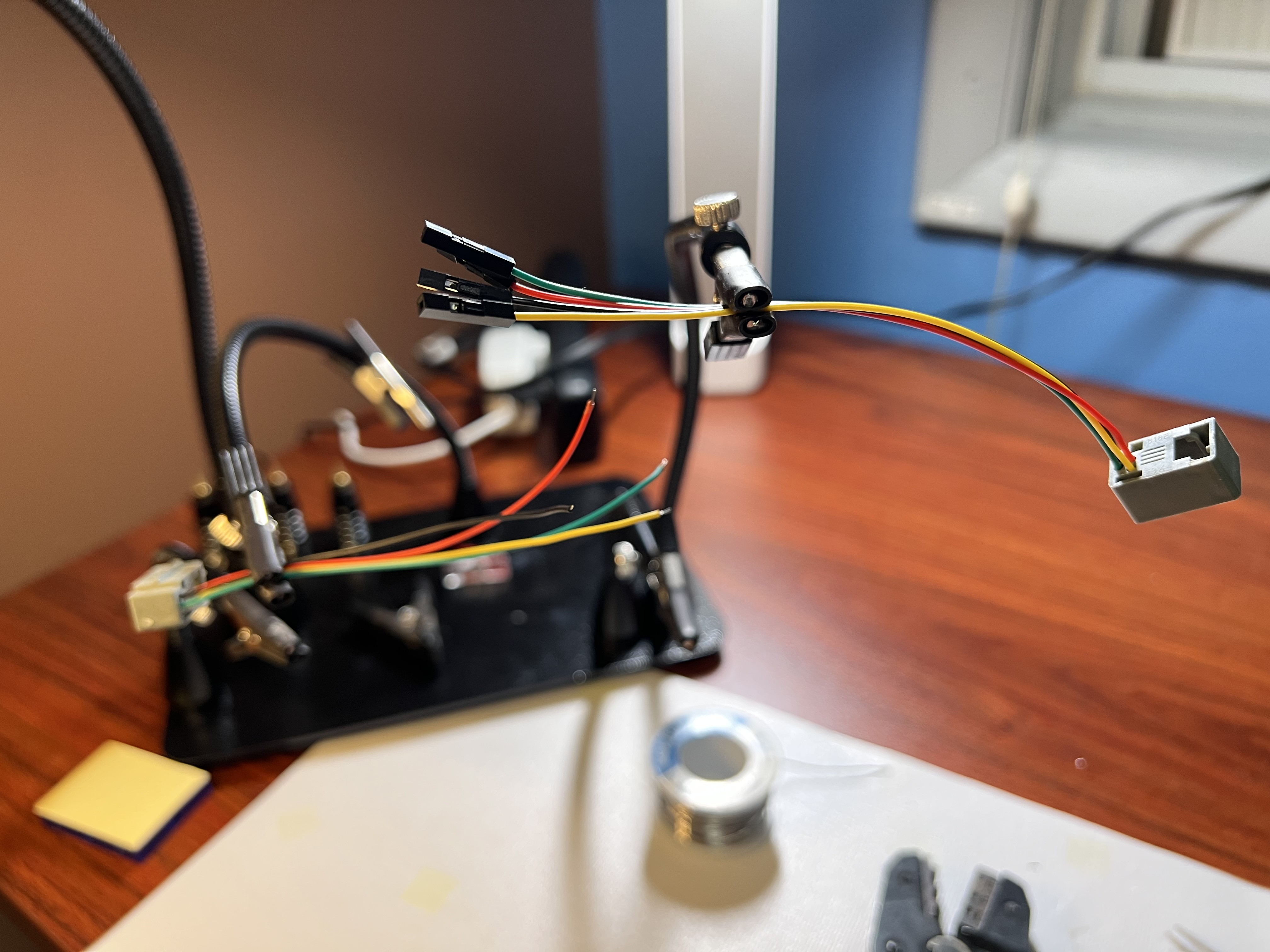
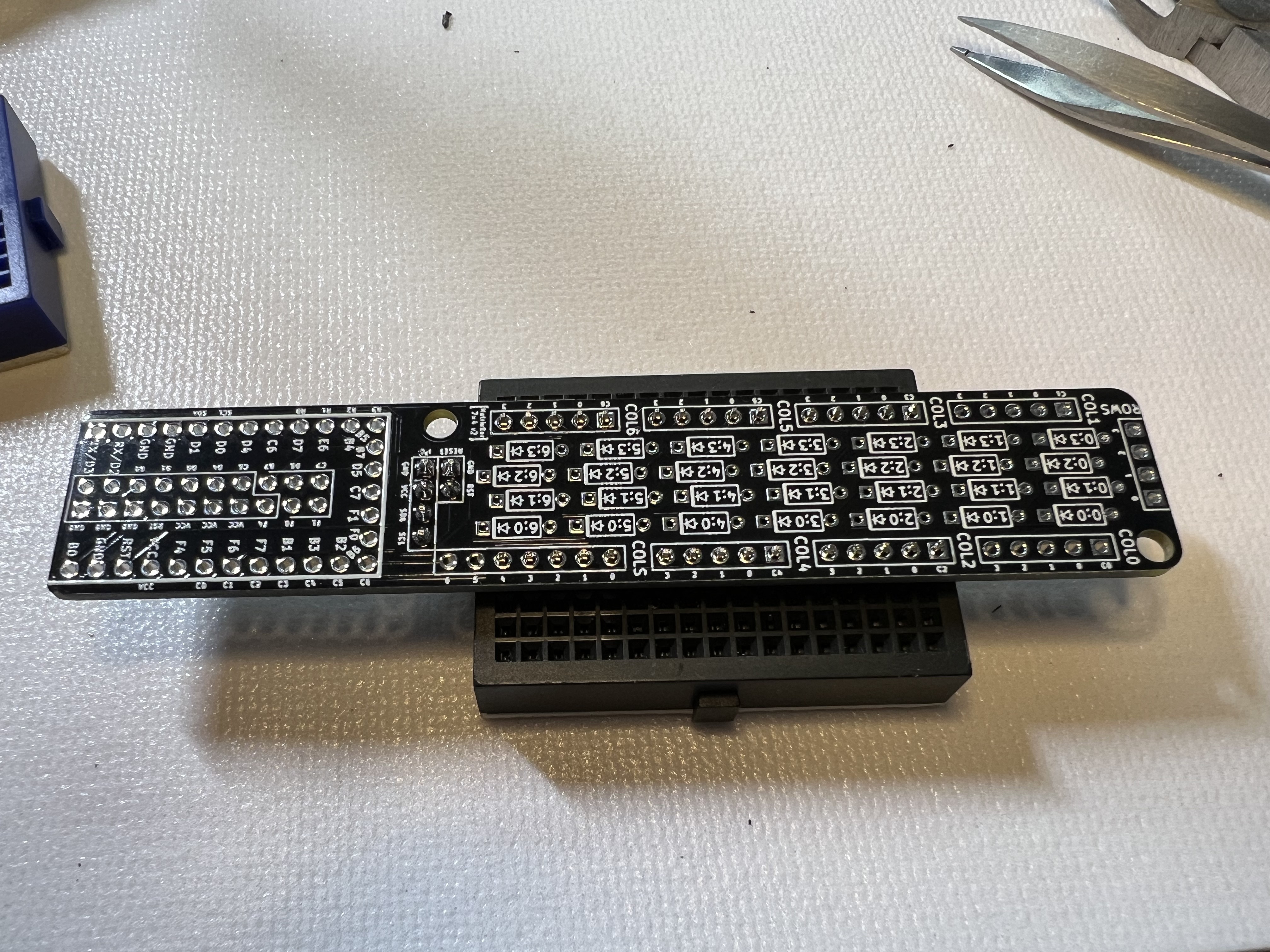
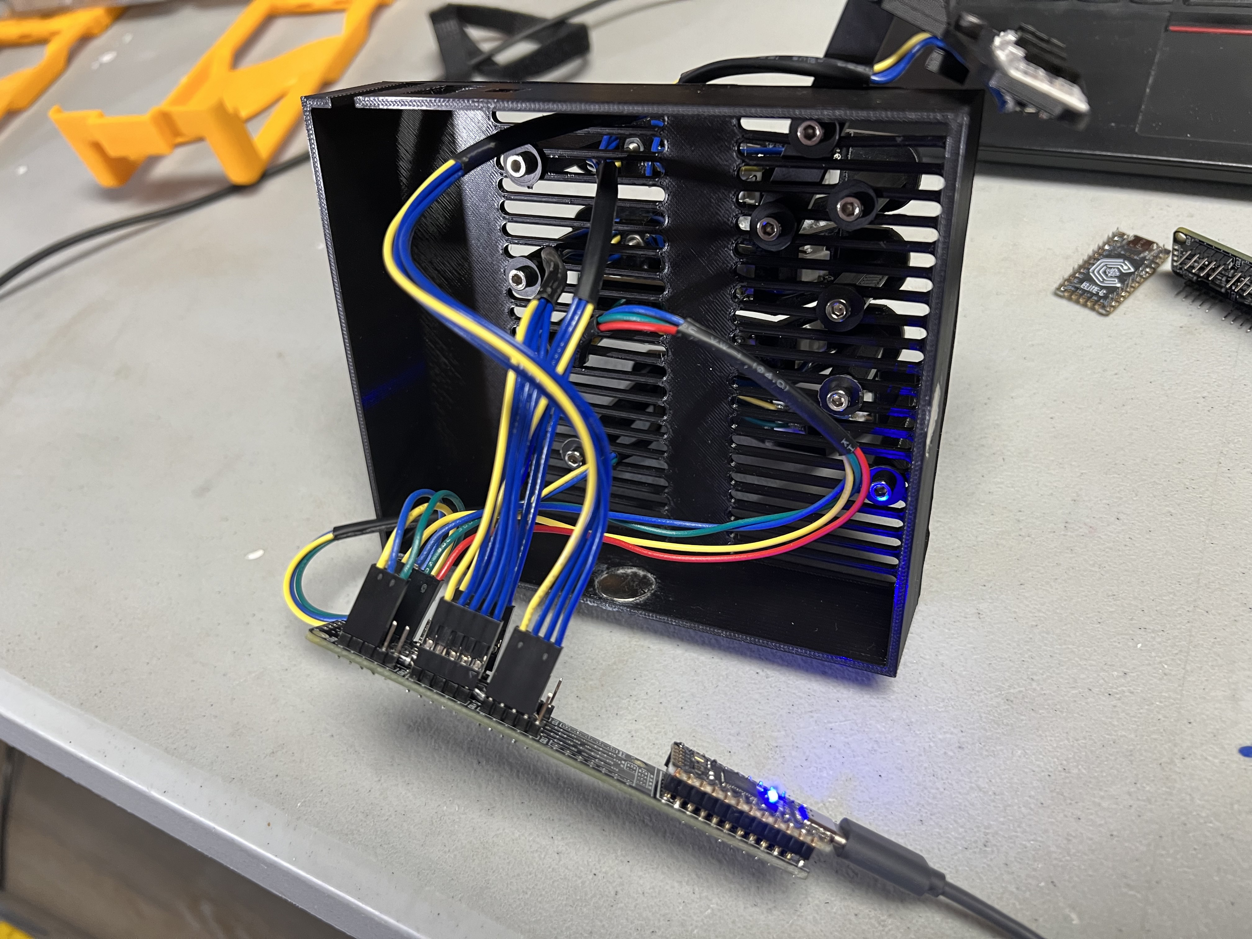
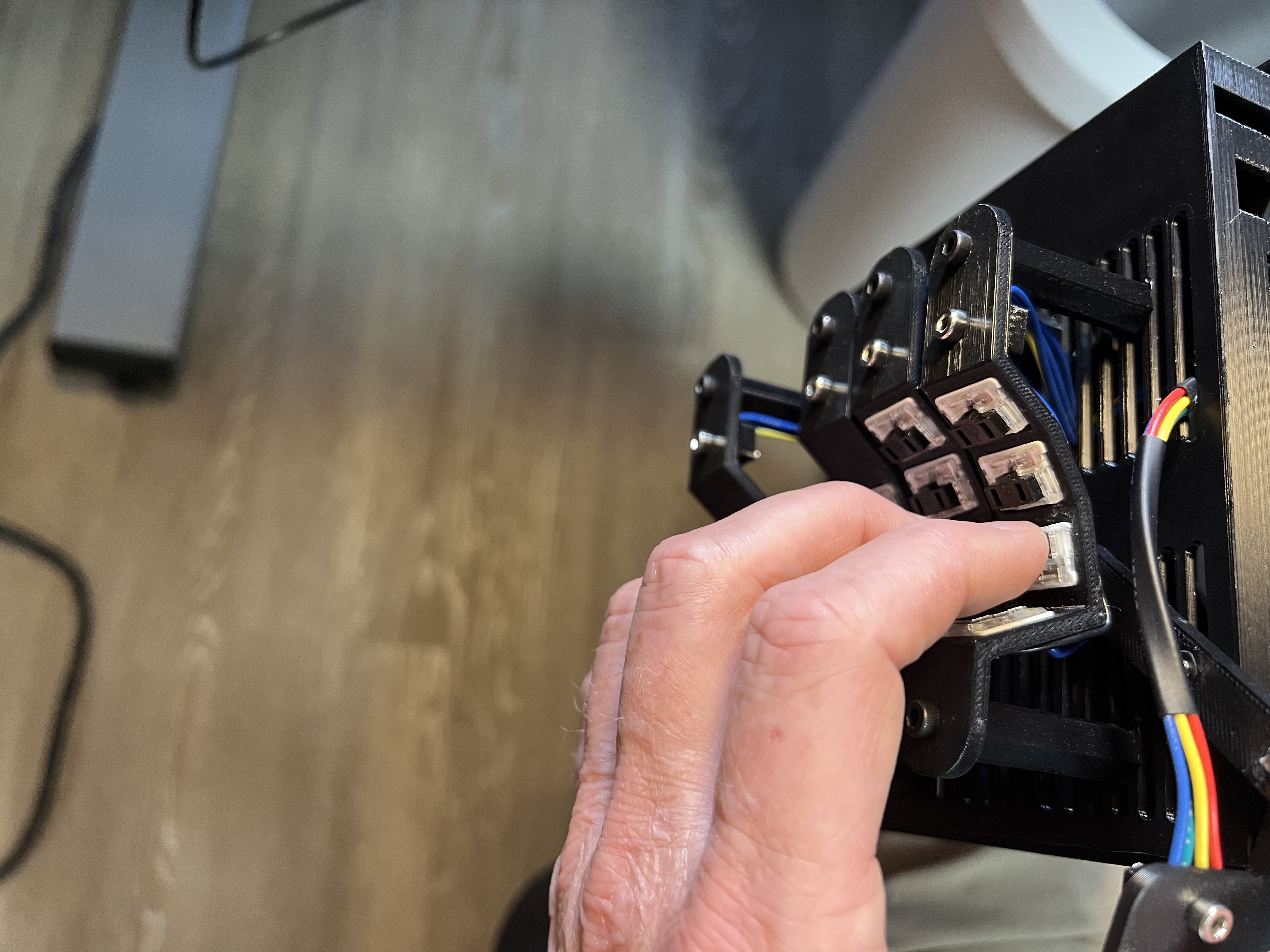
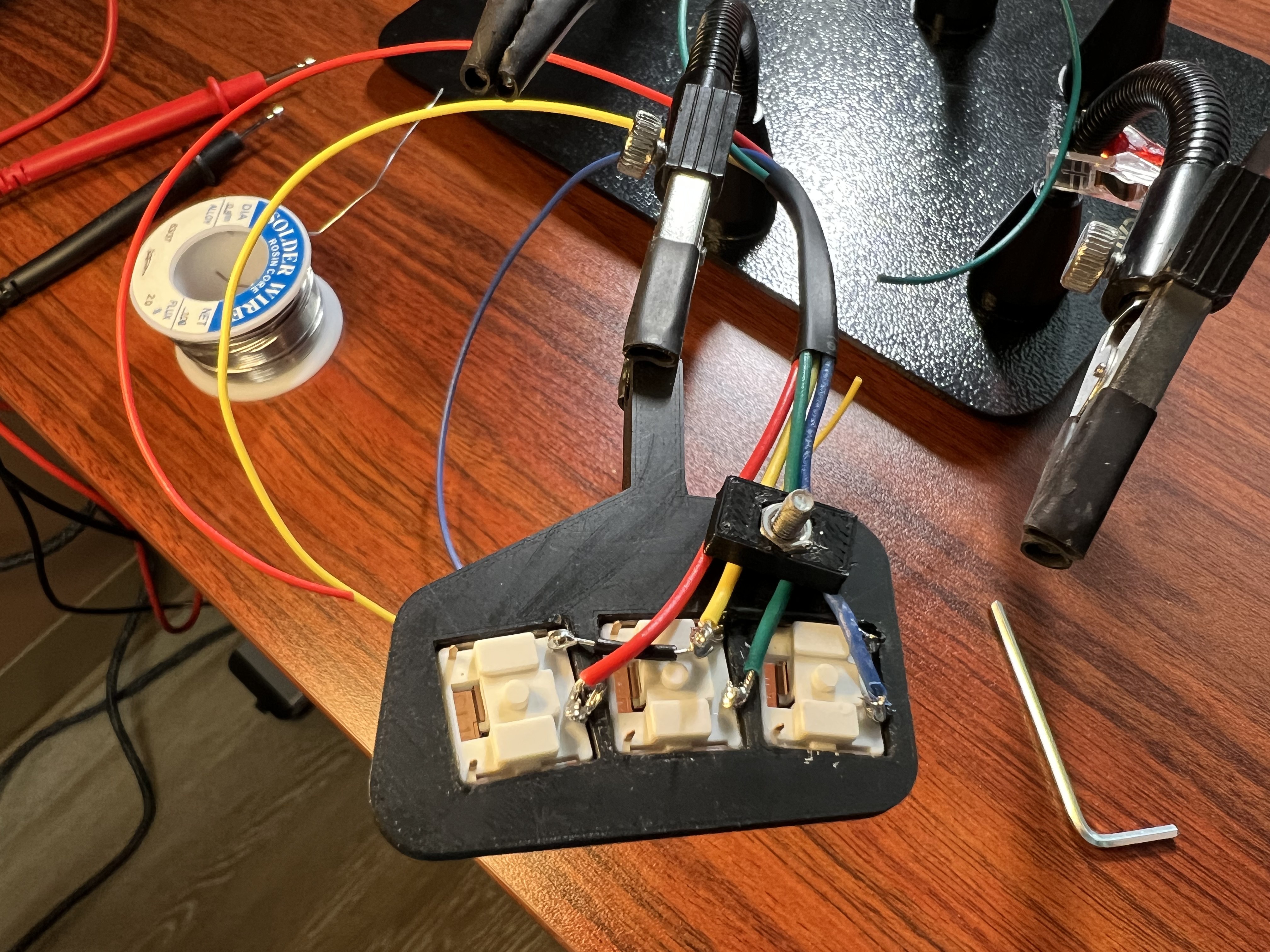
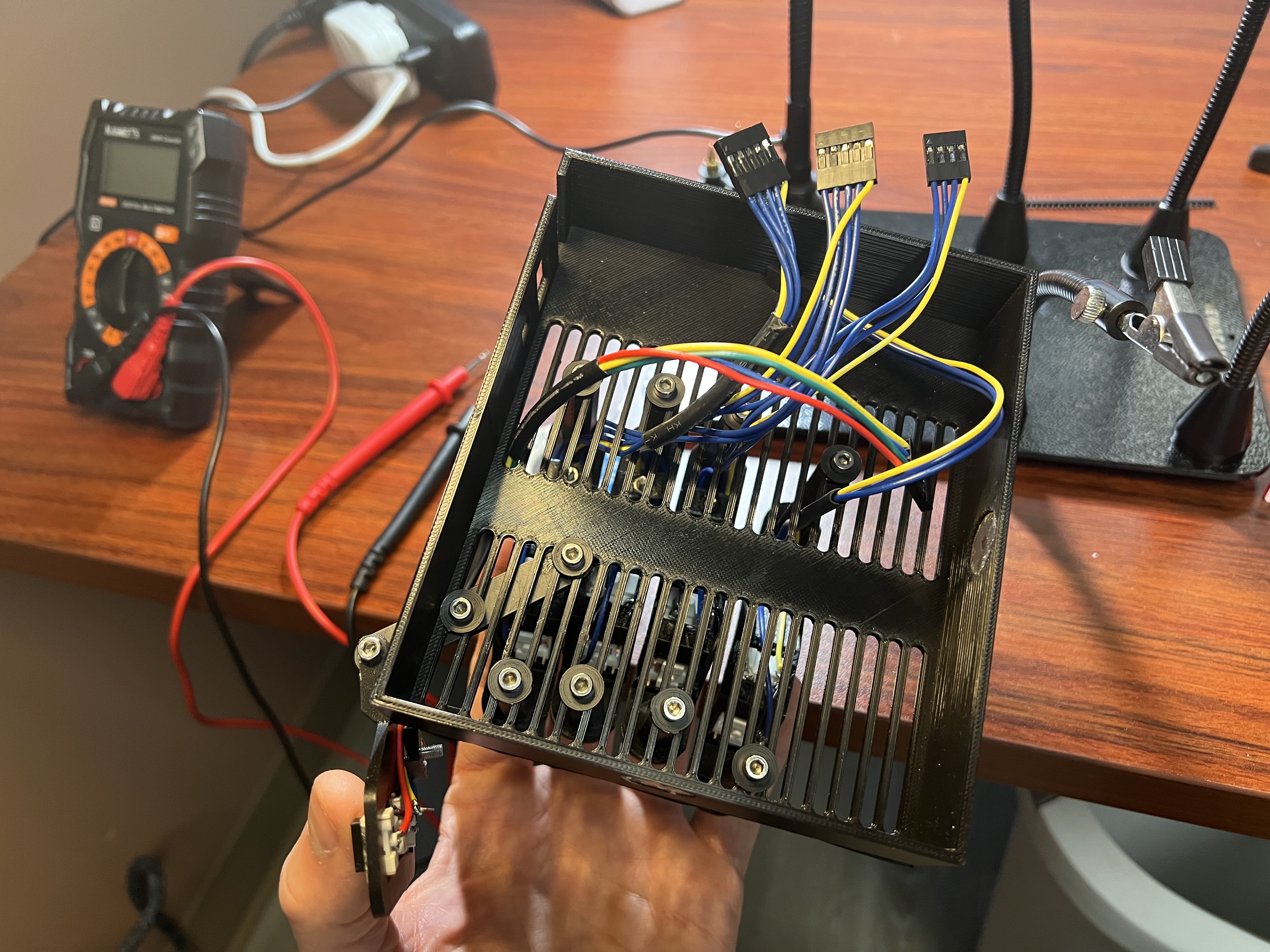
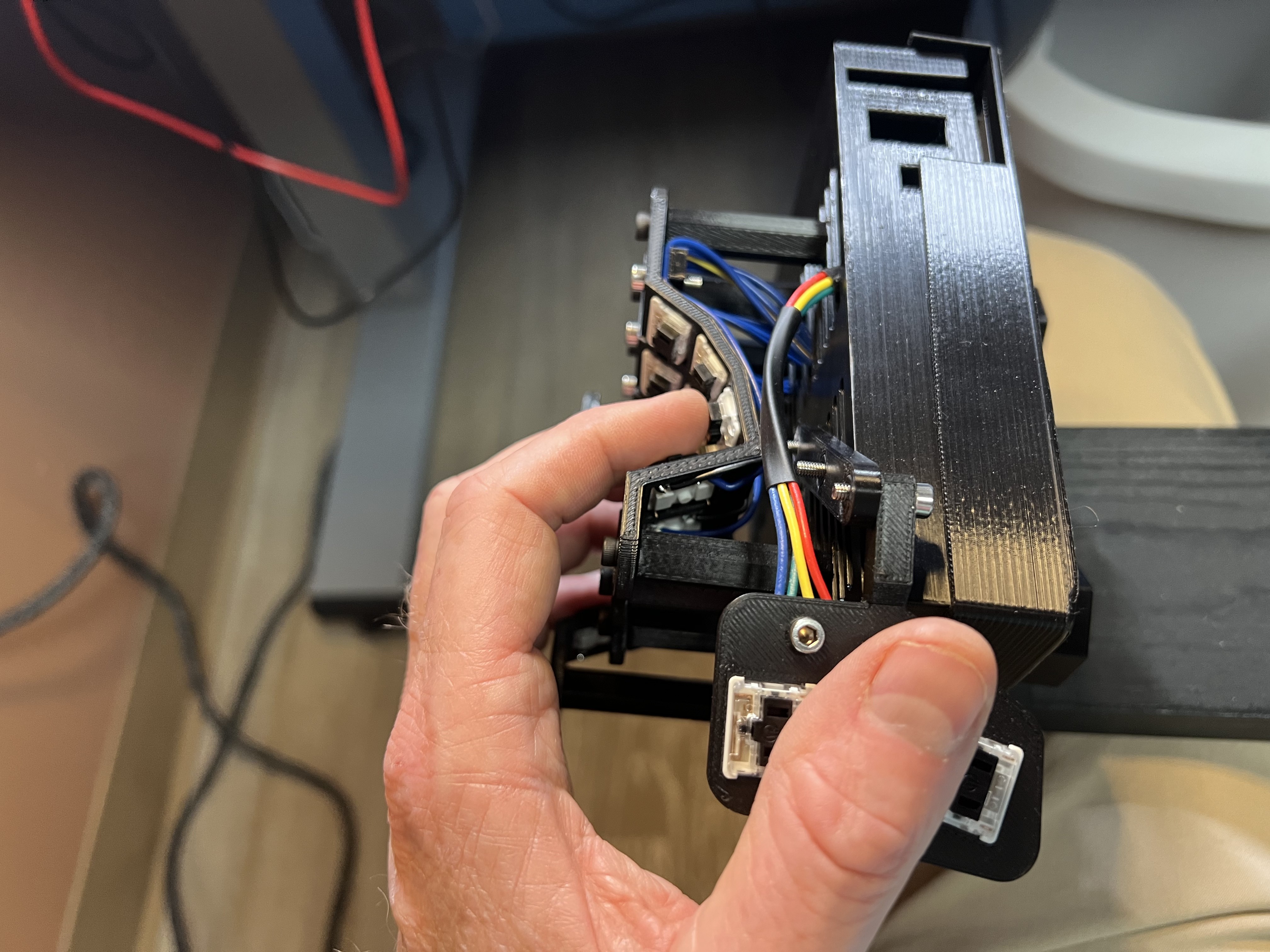
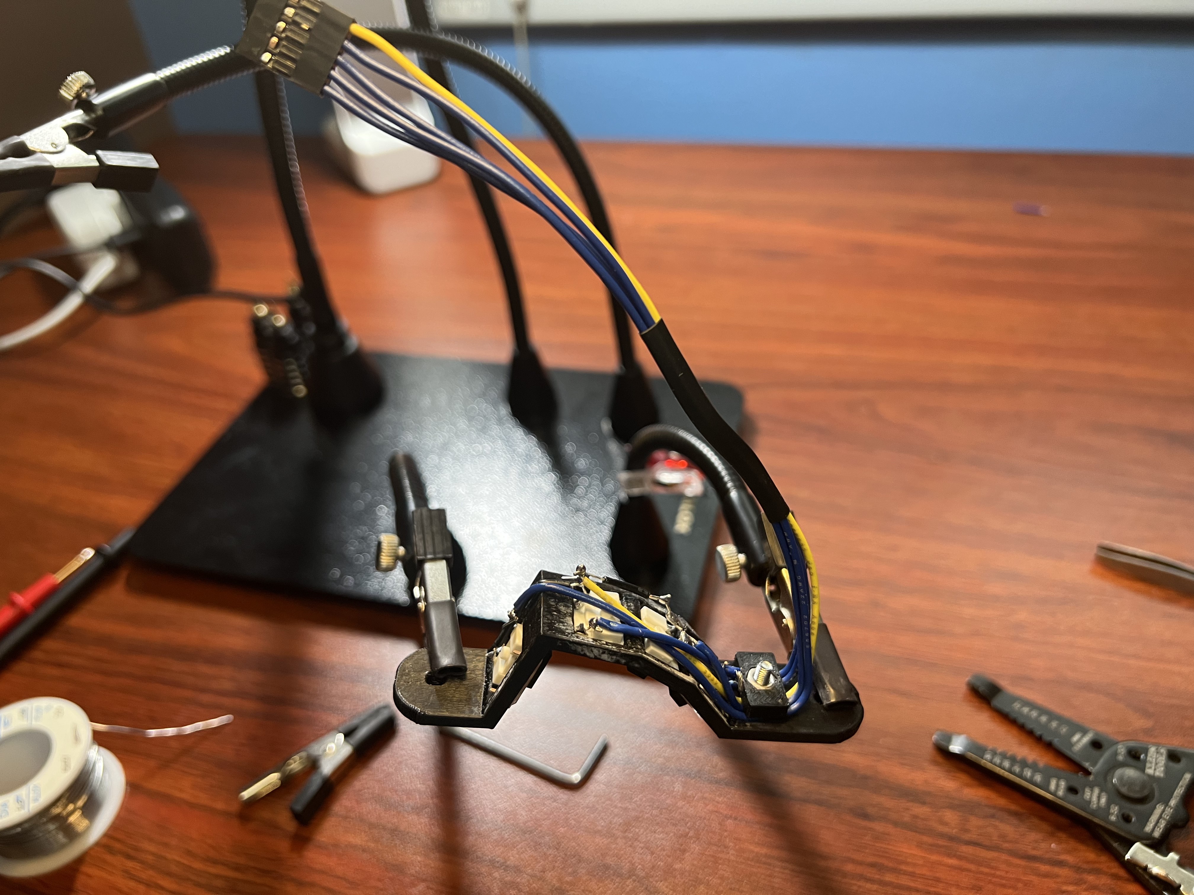
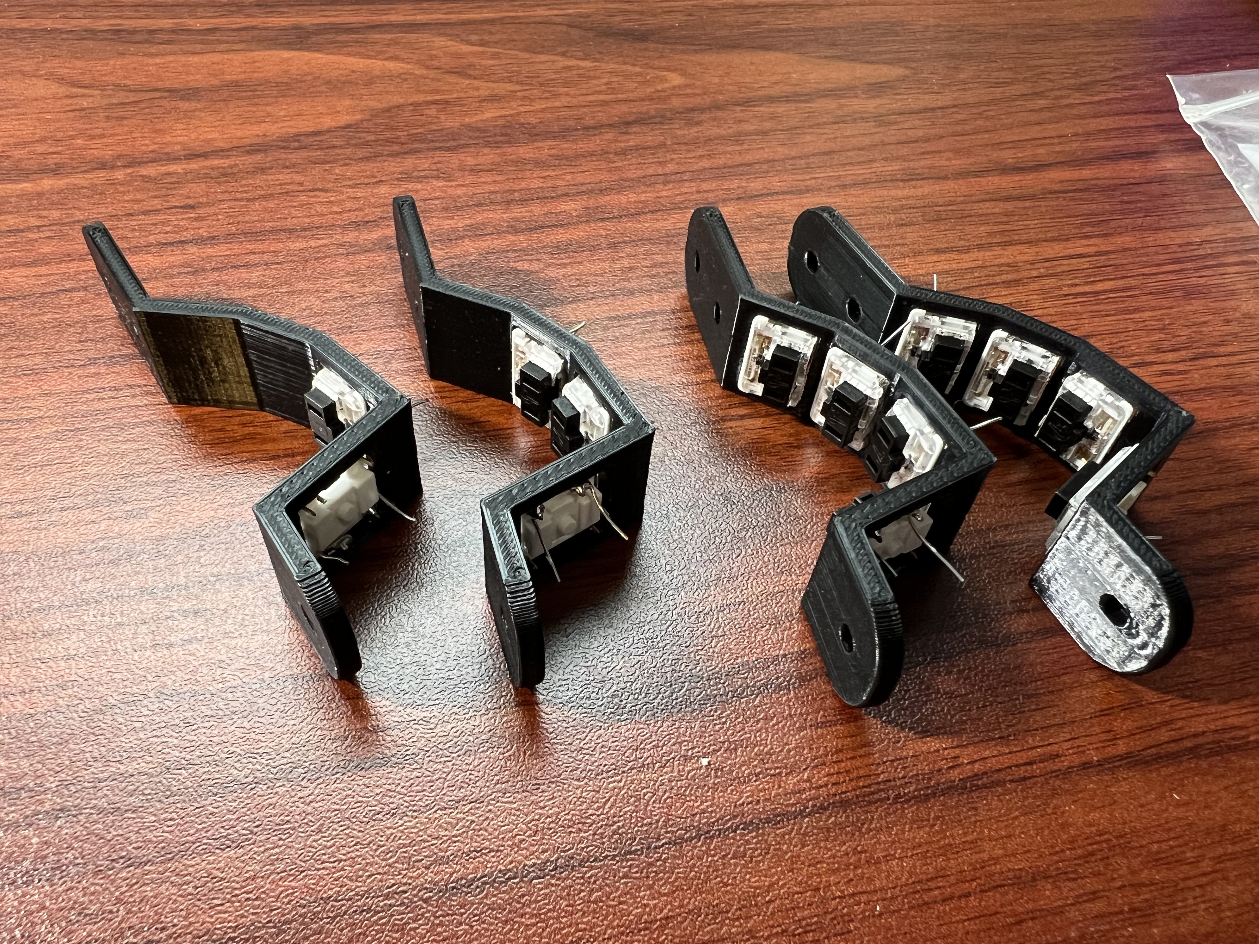
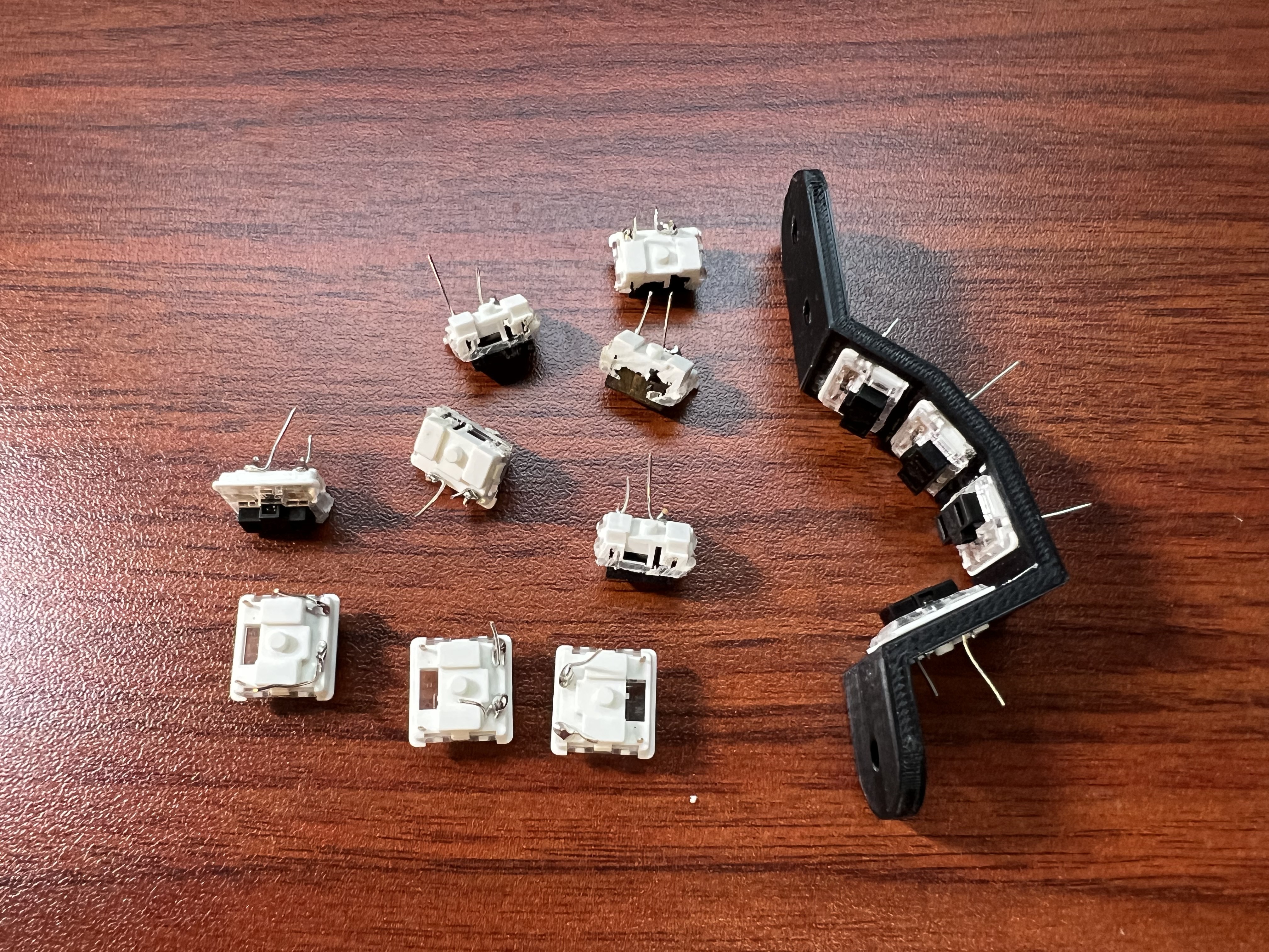
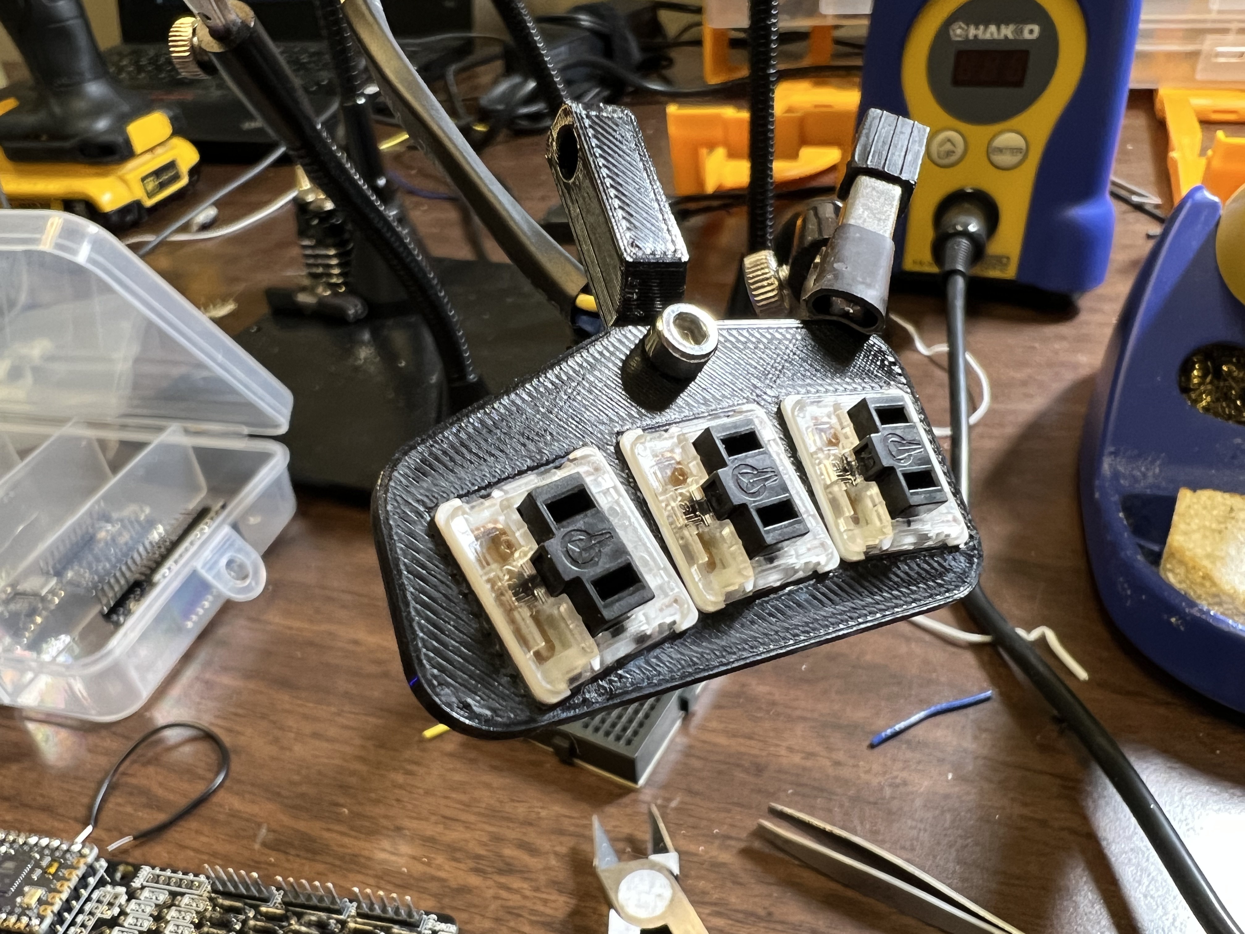
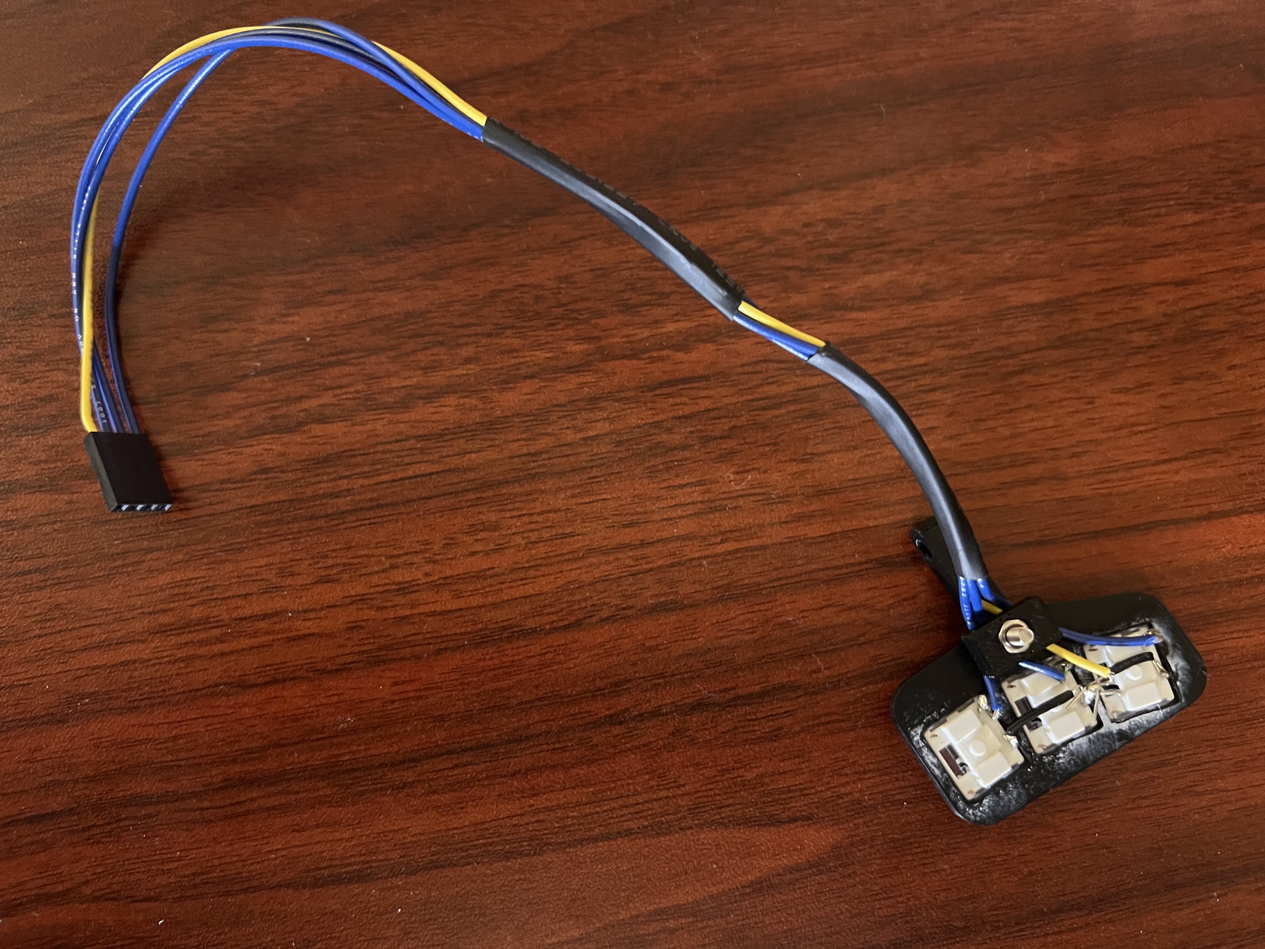
Squeezebox Keyboard v2209
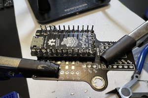
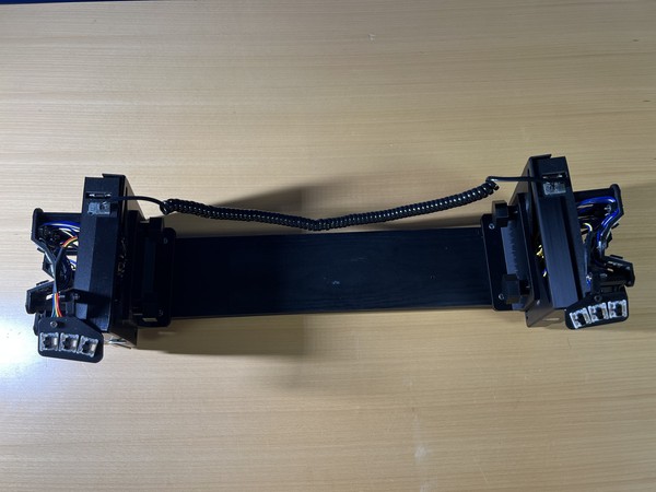
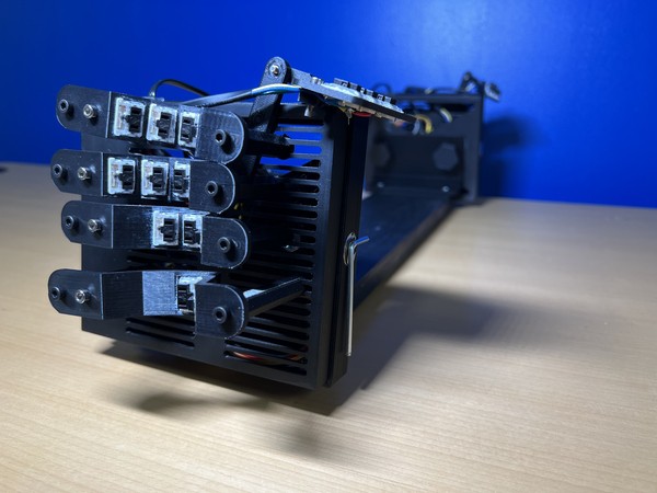
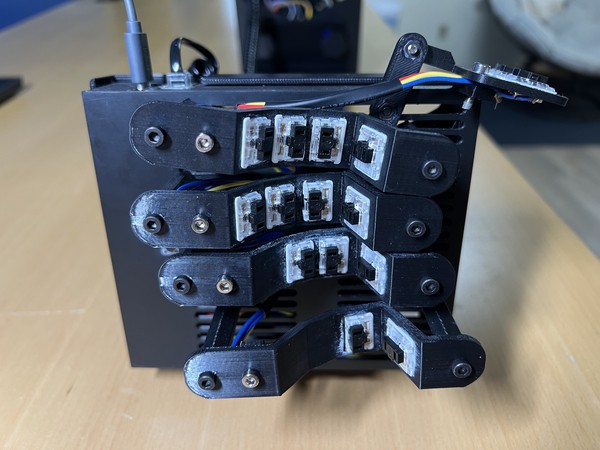
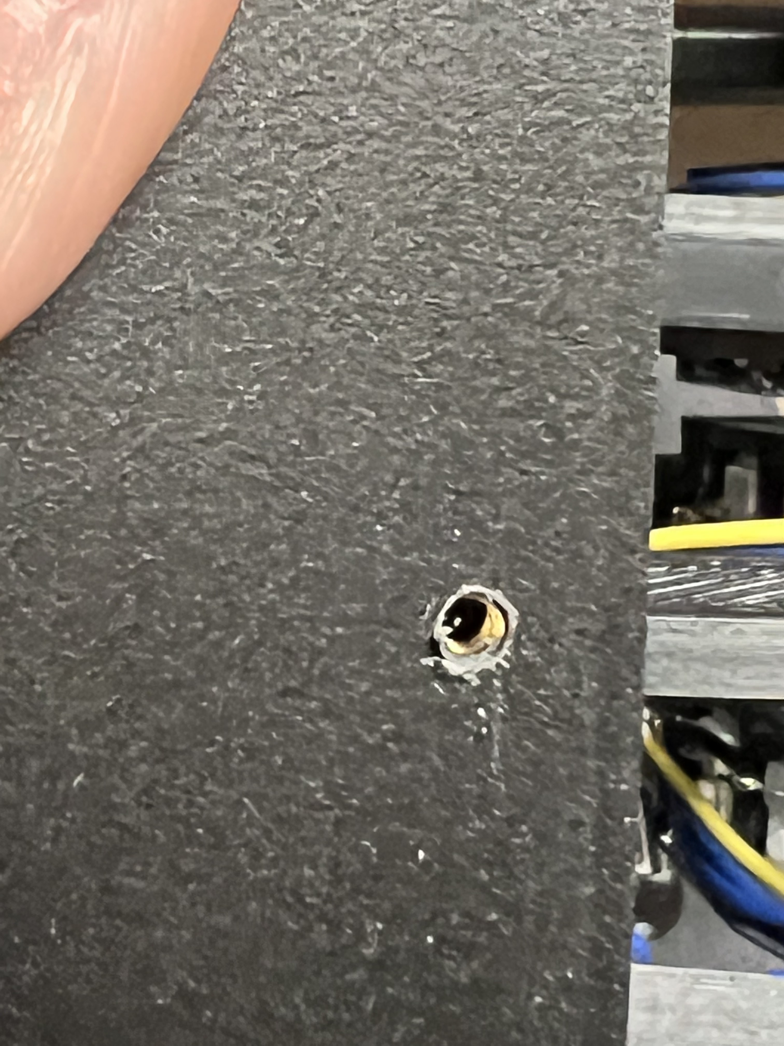
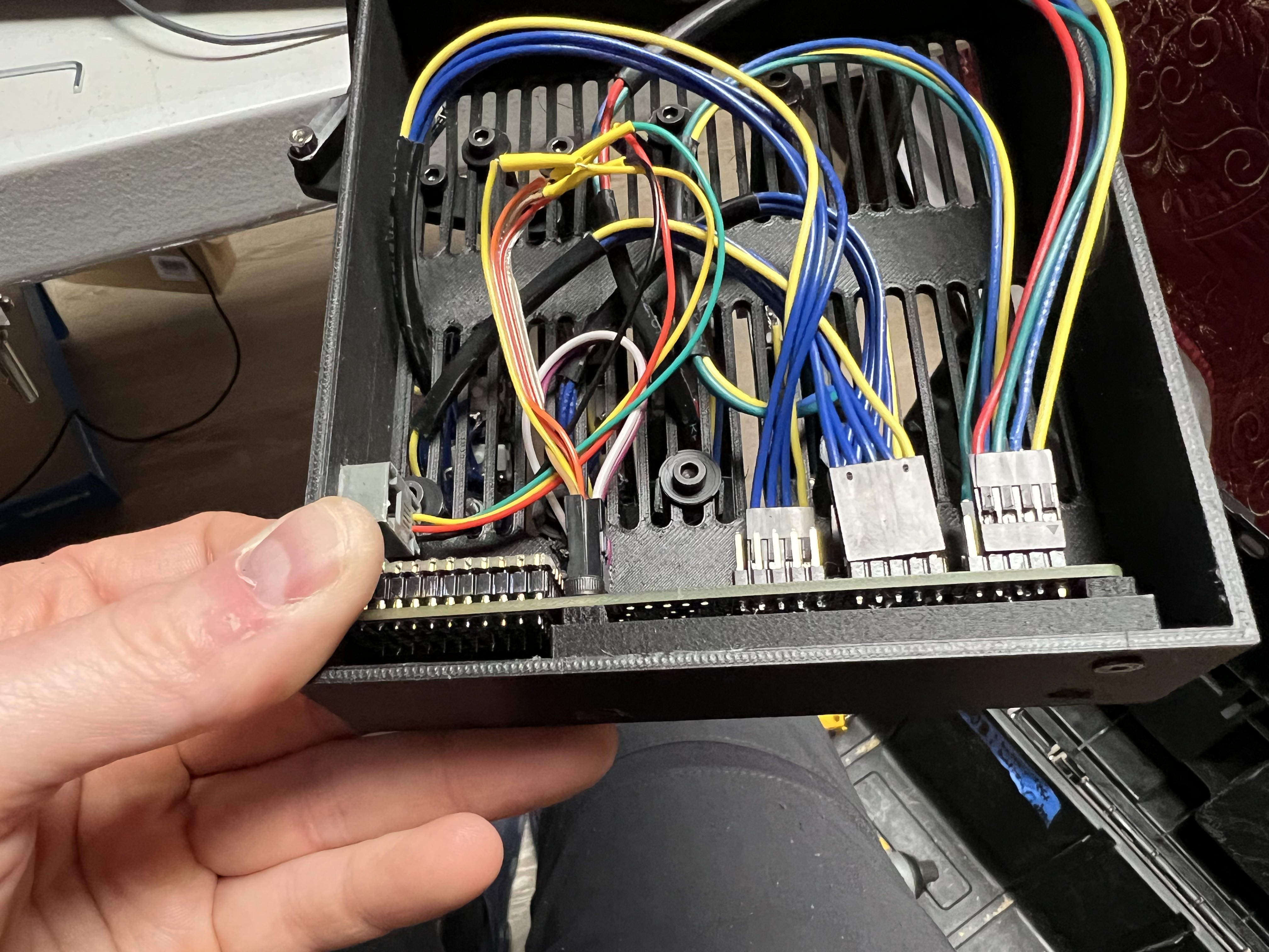
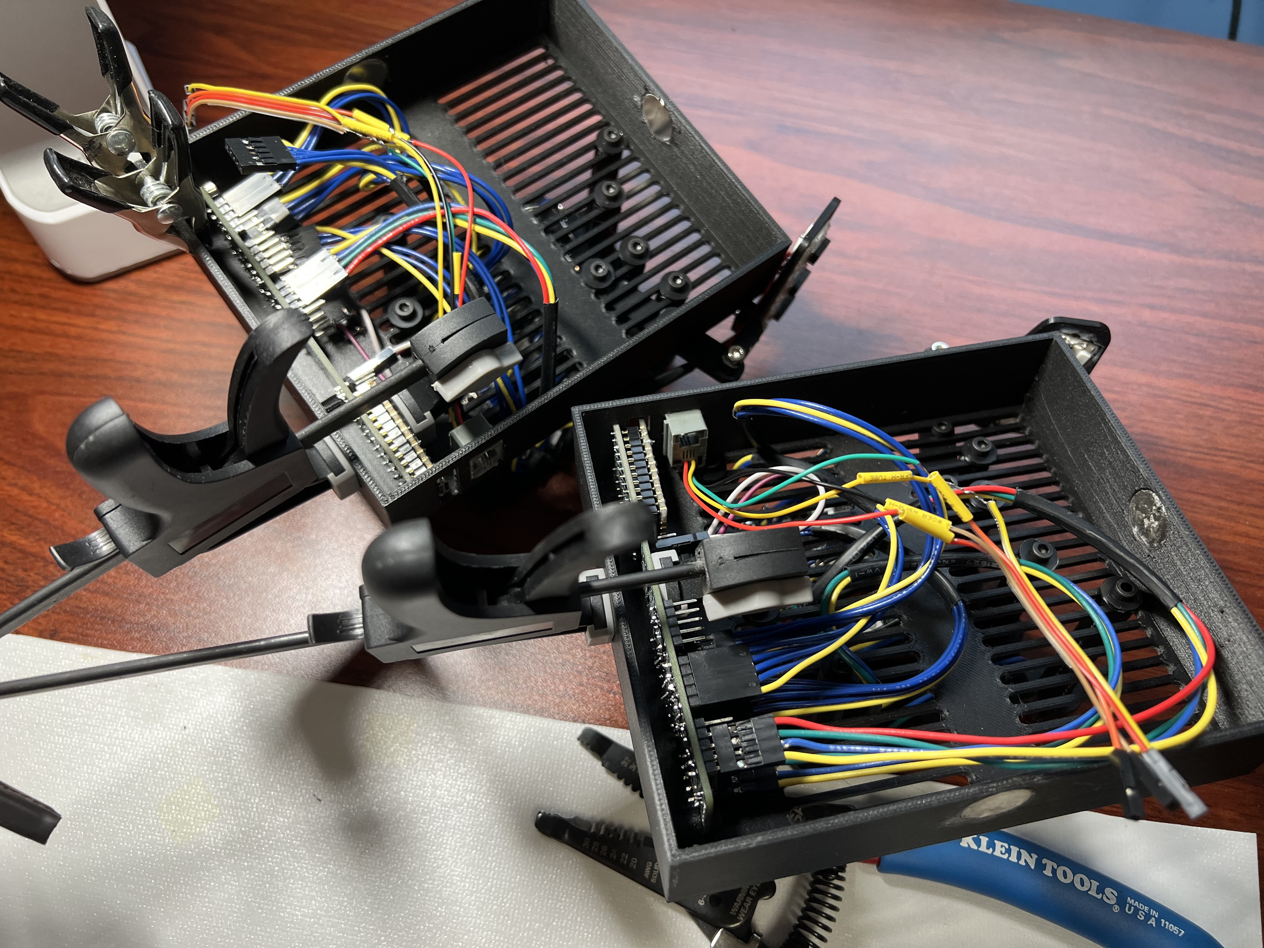
Iterating on the Squeezebox scooped split ergonomic keyboard. This version features a PCB instead of full hand wiring and choc mini switches
Become a Hackaday.io member
Already have an account? Log in.
Just one more thing
To make the experience fit your profile, pick a username and tell us what interests you.
Pick an awesome username
hackaday.io/
Your profile's URL: hackaday.io/username. Max 25 alphanumeric characters.
Pick a few interests
Projects that share your interests
People that share your interests
 Jarrett
 NFM
NFM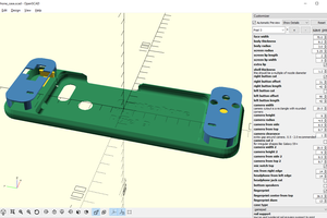
 Maave
Maave