Emilio P.G. Ficara
ESP-01: Alternative use of RSSI
Normally, we use the ESP-01 wifi module to make devices that connect to the Internet; we transmit or receive information, basically to make sensors or actuators. There are tons of applications out there, some well documented and original, others copies of copies of copies (recursive). On the one hand, there are beginners with a "shameful" preparation who pass themselves off as "specialists", well aware of the fact that there will always be someone on the Internet who understands less than them 🙂, while others are definitely "good and prepared” and reading what they propose is really interesting, even for an “insider”.
In recent years, products such as Arduino, ESP8266 and Raspberry PI have “revitalized” a hobby sector that was practically dead, with absolutely positive consequences for the entire electronics and information technology sectors. As already mentioned, however, there is also the negative factor of so many people without talent who "smear the walls", but it is an acceptable counterpart, just to see again the enthusiasm for self-construction, as it was at the (beautiful ) times of the "paper magazines".
To do some tests concerning an idea that came to my mind, I developed a little program that uses one of the “features” of the ESP-01 module in the firmware version with AT protocol. The purpose of this program is to make “beeps” when the RSSI (Received Signal Strength Indicator) measurement of a given Access Point falls below a set threshold. I decided to publish the entire project folder, containing both the executable on the path /release/Radar.exe , and the source file in FreeBASIC (with FireFly Visual Designer) on the path /forms/Form1.frm , so whoever wants to, can modify / improve the software as wanted. Let's see the screen of the program just launched:
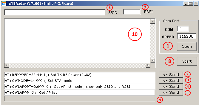
Let's go by points: (1) it is the button to open the serial communication port towards the ESP-01 module. I used the same circuit presented some time ago on my website at this link. First, we will press Open and if everything goes well, the serial port will be opened and the label on the button will change to Close . Immediately afterwards we will press in order the buttons referred to with (2) , (3) , (4) and (5). These are used to send a series of AT commands to the ESP-01 wifi module. First of all, set the transmission power to about one third of the maximum possible (27 on a range from 0 to 82); then you choose to operate as STA (station); then you are asked to use, in the CWLAP (List Access Points) command only the parameters relating to SSID and RSSI (value 6 sets bits 1 and 2, which are in fact relative to the two fields indicated). Finally, the complete list of Access Points "visible" from the module is requested. Below is an example of everything that appears in window (10) by carrying out the operations listed in order:
>Open
TX: AT+RFPOWER=27<0x0D><0x0A>
AT+RFPOWER=27

OK
TX: AT+CWMODE=1<0x0D><0x0A>
AT+CWMODE=1

OK
TX: AT+CWLAPOPT=0,6<0x0D><0x0A>
AT+CWLAPOPT=0,6

OK
TX: AT+CWLAP<0x0D><0x0A>
AT+CWLAP

+CWLAP:("MW40Wind_xxxx",-58)
+CWLAP:("DIRECT-Bh-BRAVIA",-86)
+CWLAP:("NETGEAR26",-93)
+CWLAP:("CEM_host",-36)

OK
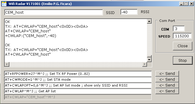
Once the list of APs is displayed, we can make a "copy" of the one we want to use and then paste it in the field referred to by the number (6) . We will therefore also take note of the RSSI value relating to the same AP and we will write it in the field referred to by the number (7) . At this point we can finally press the Start button (8) and the program will start to send a series of commands AT + CWLAP = ”APcopied”, which we can see in field (9) and then it will check the answers given by the module. If the received RSSI value is lower (they are negative numbers!) than what we have programmed in field (7) , then a “beep” will be heard. Let's see a screen of the running program:
Of course, the RSSI...
Read more »
 Michael O'Toole
 Hexabitz
 Enrico Gueli