 ElectroBoy
I am using ESP8266 module in lots of projects. But always I have to use development board for that. ESP8266 development board came as NODEMCU. Which has onboard programming IC, controlling circuitry, voltage regulators, USB port and ESP12E microcontroller. This board comes at a price of $7 to $15 depending upon the quality and brand.
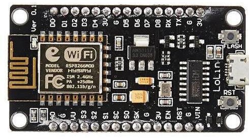
One major thing with this board is Wi-Fi connectivity over a 32bit powerful microcontroller. I made a separate tutorial in which you can learn “how to use this MCU with Arduino IDE” and “how to program esp8266 using mobile”.
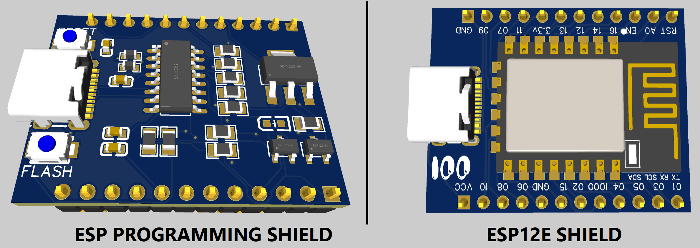
If I am doing any project, I have to use different development board which cost me $7. But I want to only utilize 32bit $2 esp12E microcontroller. I came with a solution of my ESP programming shield. Using this we can program ESP12E directly using Arduino IDE and no need on any external programmer. I made 2 different PCB one for the ESP and other for the programmer. Now you can just plug the MCU in the programmer shield and upload code to that.
Build idea:
I have to work in an approach so that 2 different PCB can be plugged into one another with pin compatibility. Whole the system can work on 3.3volts. Terminating all the external components from ESP12E shield. Making a suitable universal programmer board with upgraded programming USB section.
Components required:
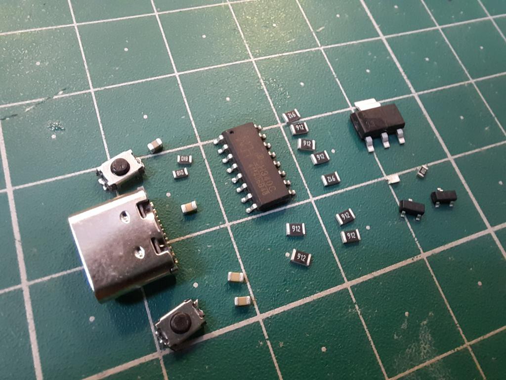
- CH340C programmer IC
- 1k, 10k, 470R resistors 0603
- Led 0603
- 100nf capacitors 0603
- Tactile SMD buttons
- AMS1117 3.3v regulator
- Type C USB jack
- ESP12E MCU
- BC847 SMD transistors
- PCB Shield from JLCPCB
Circuit diagram for programmer:
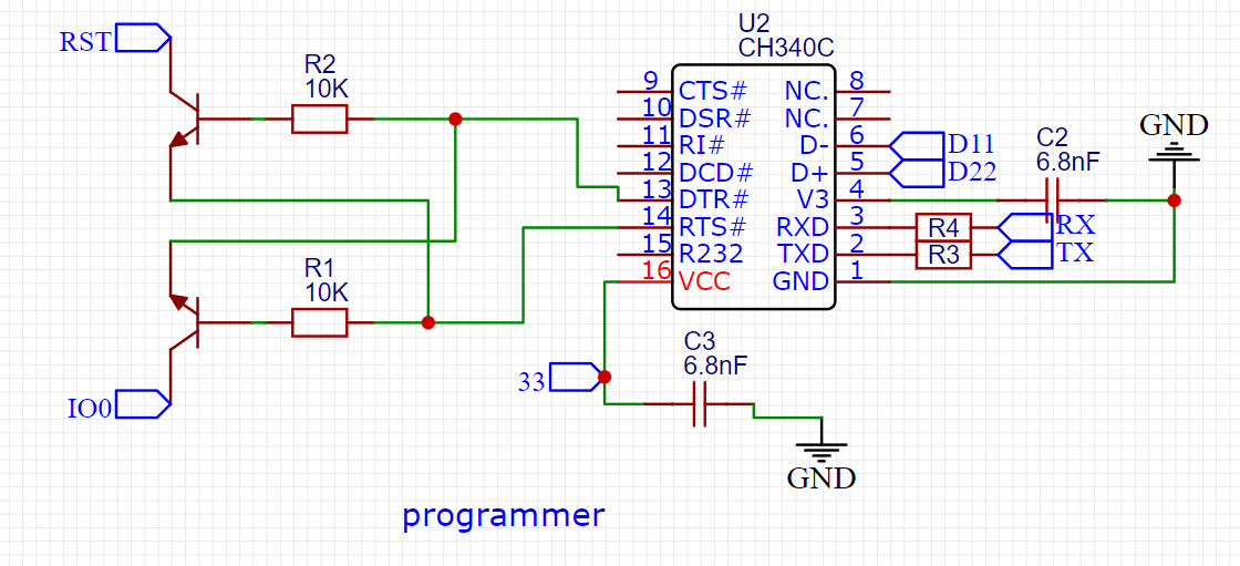
CH340C is a USB to serial programmer which has internal 12mhz crystal oscillator. 2 transistor are used to reset and flash the microcontroller automatically while in programming mode. Otherwise, we have to do it manually. Led indicator for Reset pin and give a notification after successful programming. AMS1117 keeps the microcontroller on a logic 3.3v level.
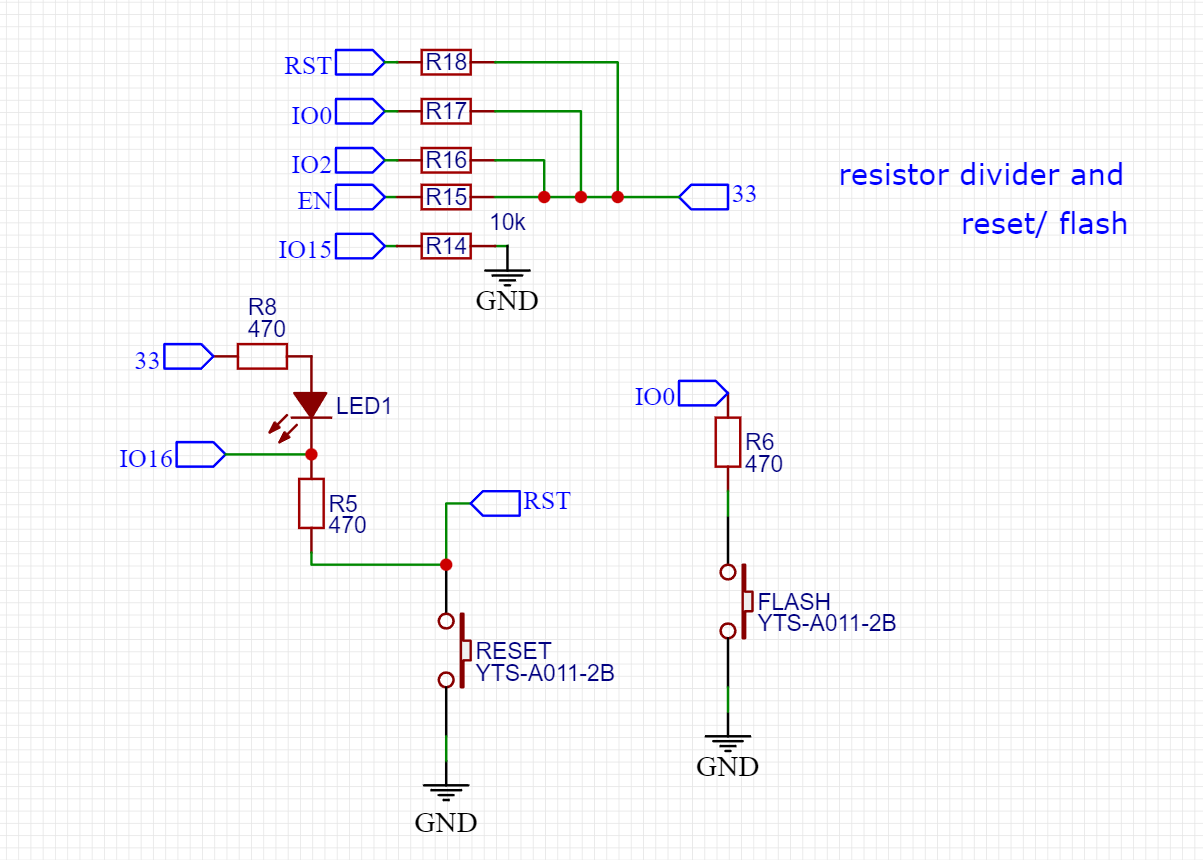
USB type C makes the board more compatible. All the 10k resistors are used to set a logic level on the required pin. You can see the circuit diagram in case you want to use any other programming IC. But keep in mind that only CH340C variant of CH340 family has inbuilt crystal oscillator. 100nf capacitors are used to with power input IC which filters the power supply and reduce the overall noise.
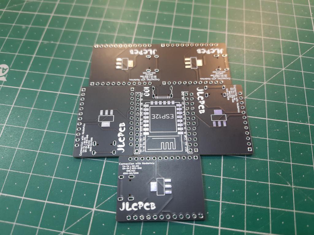
PCB specs:
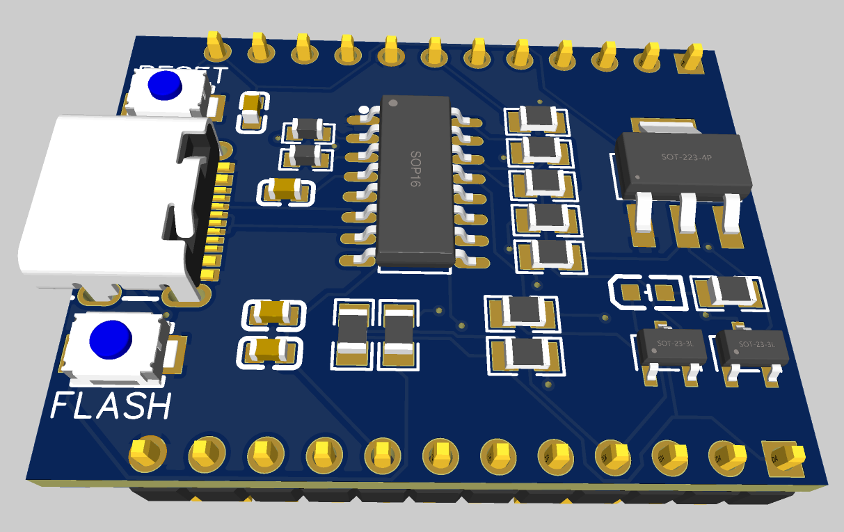
I convert the updated schematic into a PCB and then make a compatible shield according to my ESP12E shield. I mount all the components to bottom layer so that they are visible while programming and easy to troubleshoot. If you want to use the same designs as mine then get them from here.
I order the PCBs from JLCPCB with stencil which cost just $2 for the PCB and $7 for the stencil. JLCPCB is the leading PCB manufacturer from China offering a lots of offers on new user sign-up. Just upload you Gerber file set the parameters then checkout the cart and get your boards just in 7 days.
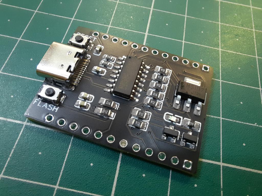
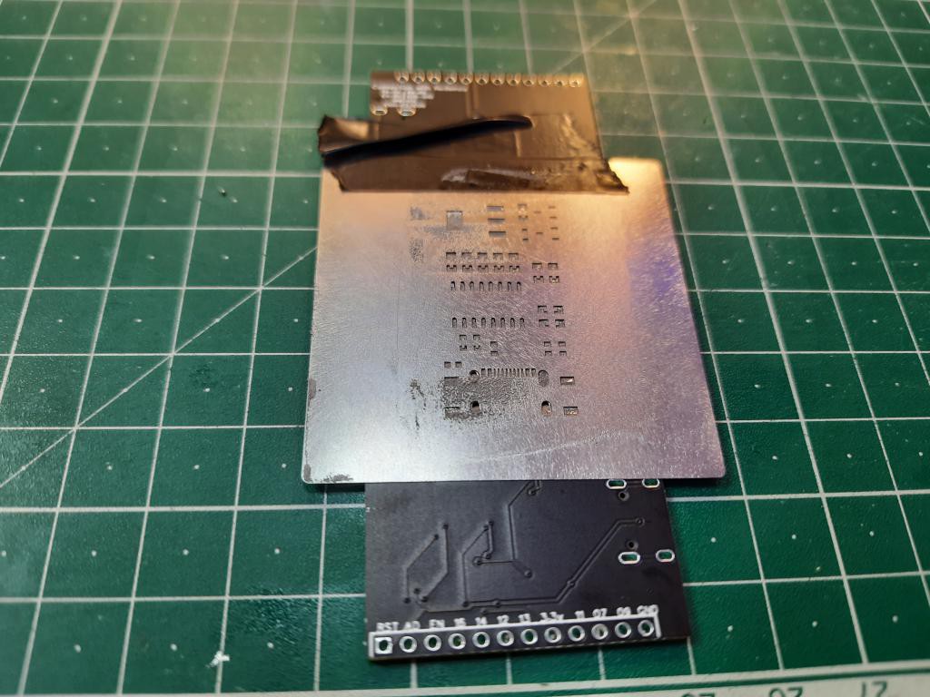
PCB assembly and soldering:
I am using stencil service from JLCPCB, which allows to distribute the soldering paste evenly on PCB and using a simple soldering station we can solder all the components. A very easy method of soldering the SMD components. Here all the components are placed only on bottom layer so I ordered the small custom stencil. If you don’t have components or not good at soldering then try to go with SMT assembly service from JLCPCB starting from just $8.
Now two types of headers are required here, if your esp12E shied has male pins then solder female headers to programmer PCB. Sometimes it is very difficult to test the small soldering pins like with TYPE C connector.
First test and troubleshooting:
Before giving power check the power connections in continuity mode and if everything is okay then great. But if there is continuity issue then check the short position. It may be through the USB or excess soldering. The overall system will consume less than 200mA when working. If the current exceeds more then there is any minor short somewhere. Try to resolve the issue by resoldering by hot air gun.
Plug in and ready to program:
Plug in the programming shield into ESP12E shield. Then connect the USB to programming shield. Keep in mind only programming shield has data lines for chip burning. ESP12E shield also has a USB type C but this is only to give power to MCU.
Arduino IDE settings:
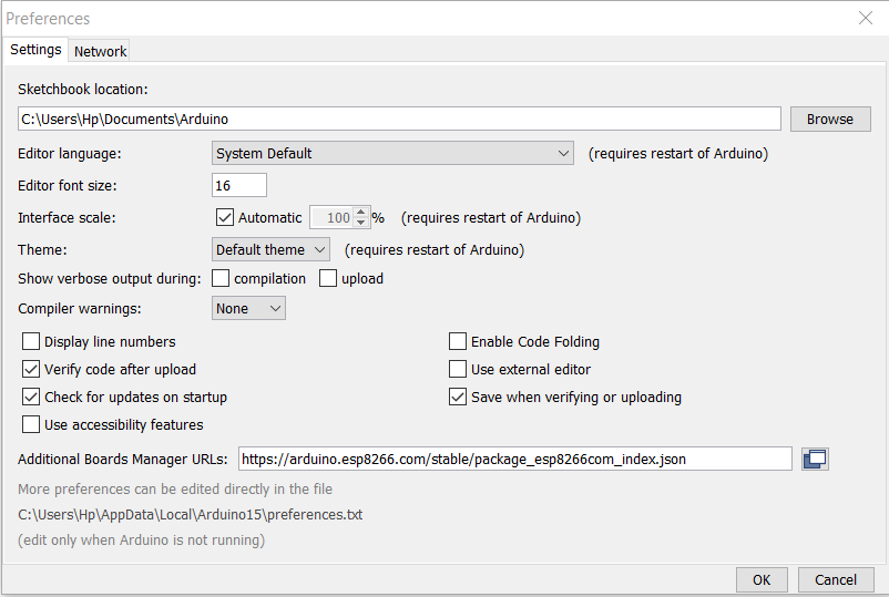
Paste this code in the preference section, under files menu.
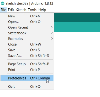
https://arduino.esp8266.com/stable/package_esp8266com_index.json
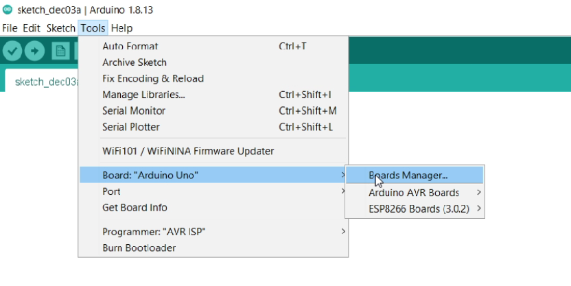
Download the ESP8266 board from board manger in tools section.
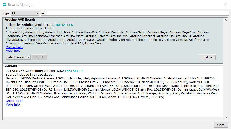
Choose ESP12E MCU and then select the COM port and upload the sketch.
From the examples you may get some example code which can be used for initial testing.
Arduino test code:
// the setup function runs once when you press reset or power the board
void setup() {
  // initialize digital pin LED_BUILTIN as an output.
  pinMode(LED_BUILTIN, OUTPUT);
}

// the loop function runs over and over again forever
void loop() {
  digitalWrite(LED_BUILTIN, HIGH);   // turn the LED on (HIGH is the voltage level)
  delay(1000);                       // wait for a second
  digitalWrite(LED_BUILTIN, LOW);    // turn the LED off by making the voltage LOW
  delay(1000);                       // wait for a second
}
First Run:
To do a test I plugged the ESP shield into programmer and tried to upload the sketch. In the PCB I found some mistakes in circuit that are corrected later. But don’t worry, you can download the updated fully working version from description. Now my code is running on this microcontroller.
This programmer is small, universal and insane.