 Keerat Singh
What is it
Our solution adds sensors to a mason bee house so that beekeepers can be confident their bees are active and healthy, and the house is clean. If they are alerted when unwanted visitors like parasites are entering the bee home, they can be proactive about preventing their spread. Additionally, by alerting the beekeeper
when a tunnel is full of mason bee eggs, that tunnel can be removed and kept somewhere safe, away from mold and parasites.
Implementation: At the core of our solution are capacitive sensors that non-intrusively detect bee behavior in tunnels. These sensor readings will be interpreted to determine when bees are entering and exiting, how much of the tunnels are being actively used, and when unwanted intrusions occur.
Capacitance Measurement
The capacitor sensors that form the heart of our project are based on research conducted at the University of Prince Edward Island in 2005 [5]. In their paper “Capacitance-based sensor for monitoring bees passing through a tunnel”, they describe a setup where they directed bumblebees to enter their hives through tunnels. In these tunnels, they had set up a “two-capacitor set-up along with an AC bridge and phase-sensitive detection” which “produced an asymmetric double pulse for each bee passage”. We had two choices for the capacitor setup as specified in the paper - we could either use parallel plates or ring-shaped sensors. We chose to use the ring sensors because it was easier to fit those around
the tunnels in a small package. Previous research also indicated that the ring design was more sensitive.
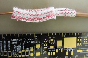
The spacing and measurements of the copper rings that form the capacitive sensor were initially chosen based on recommendations from previous research in tunnel-based insect monitoring, and fine-tuned with trial-and-error prototyping in the lab. We originally planned to make the sensor rings out of thick, 9 gauge copper wire, but our machinist, Mr. Glen Hedin, advised that this would be too difficult to bend into rings of our desired radius. Instead, we used cut sections of copper tubing to meet most of our requirements for the rings while also allowing for practical machining methods.
The circuitry associated with the sensor also went through many design iterations. At first, we constructed an instrumentation amplifier ourselves using multiple op-amps. However, after extensive prototyping, we found that our constructed instrumentation amplifier did not produce repeatable, reliable results. As a solution, we purchased the AD620 instrumentation amplifier because of its matched resistor pairs and quality control testing. The AD620 allowed our system to be very precise and enabled our AC bridge to be reactive to even small imbalances between its two sides.
Some of our first prototyping was centered around selecting the AC bridge’s driving voltage. Based on lab tests, we knew a higher amplitude sinusoidal waveform would make the sensor more responsive to insect movement, so we decided to use a 5 V waveform since it provided the necessary sensitivity without requiring extra hardware to implement.
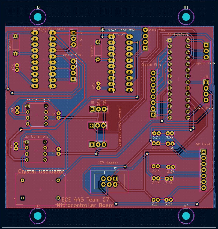
We made custom PCBs for the electronics of this project. There is a board with all the electronics associated with the sensors, and there is a board for the common components that all three sensors would use.
More details on the project can be found in the engineering report in the files section.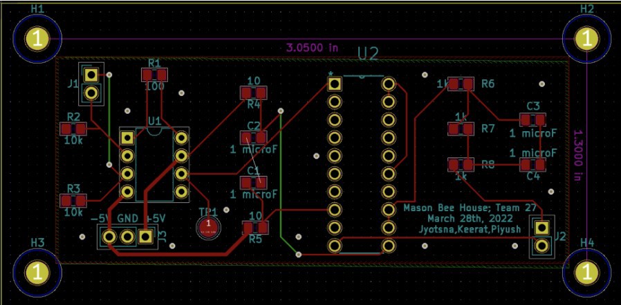
 Kenji Larsen
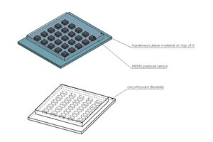
 Aman Garg
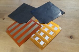
 chris.coulston
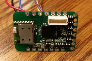
 Statutory Therapy