 John Forsyth
Review of Objectives
The objective of
this project was the design and creation of a home monitoring system.
It has several sensors throughout the home, which measure various
quantities and report them to a Raspberry Pi. The Raspberry Pi then
presents this data on a webpage, which allows for viewing of
information on trends occurring in the home. It also functions as an
alert system that makes the user aware of any unauthorized entry to
the home or the presence of fire. In the case of fire, the system
also controls parts of the home to both unlock a door and turn on
lights.
Review of Deliverables
The deliverables
for this project included monitoring aspects of the home, control
systems for the home, hosting a website, and acting as an alert
system. The deliverables related to monitoring the home included
gathering information on light usage. As well as the air quality,
temperature, and humidity in the home. Occurrences of power outages
were also to be monitored. Detecting whether doors are open or closed
was also required. Finally, the system would also detect the presence
of smoke. The control system deliverables for the home included
engaging and disengaging an electromagnetic lock and turning on and
off lights. These controls were also to be used to cause the lights
to come on and the lock to disengage if a fire were detected. The
website was to be created to display the aspects of the home being
monitored and to display them in a user-friendly manner. Finally, the
system was to act as an alert system such the user is informed when a
door to the home opens.
Technical Implementation
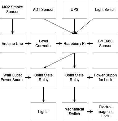
The first step in creating this project was setting up the Raspberry Pi 3 B+, and ensuring that it would boot successfully. Next, the BME680 sensor was attached to the Raspberry Pi. This task required soldering female headers to the BME680, and then connecting wires from these headers to their appropriate pins on the Raspberry Pi. In order, these pins are 1,3,5, 7, and 9. These specific pins were selected as they provide the sensor both power and I2C communication with the Raspberry Pi.
A program was written in Python to read the environmental information sent from the sensor. Using Python was a learning experience throughout the entirety of this project, due to only having used it to create one program prior to undertaking this project. To read data from the sensor a Python library supplied by the manufacturers of the sensor was included in the program.
Once the information could be read from the sensor, it was necessary to figure out a means of storing it in a database. MySQL was selected as the database software for this project due to its online presence and thorough documentation. MySQL was another major learning experience throughout this project. As a complete novice, it required much trial and error before the necessary level of competency was achieved to create a location for the BME680 data to be stored. Next, the Python program used to read the sensor’s information was altered so that it would send this information to the appropriate MySQL table. This was achieved through the use of a library called mysql.connector.
The next step in the project was displaying the stored environmental information on a webpage. To accomplish this, an Apache server was created on the Raspberry Pi. Luckily, its creation was far more straight forward than other aspects of this project and didn’t have a large learning curve for a complete novice. Once set up, the software broadcasted a webpage on the local network. To alter what appeared on the webpage, the Apache server’s default index file was edited. Through a combination of HTML and PHP (as well as mysqli which allows for PHP to interface with MySQL) it was possible to edit this file such that the webpage displayed the MySQL table containing the environmental information log. Although not part of the original proposal, the environmental monitoring presented on the website was expanded upon to include a secondary table which exclusively presents the current environmental status. To do this the process of creating the previous program to read from the BME680 and send the information to a unique MySQL table was repeated. However, this time the program was changed to update the MySQL table instead of adding new values. After getting this program operational further editing of the Apache server’s index file was done to display this second table.
As per the proposed technical plan, to monitor for power outages, an uninterruptable power supply (UPS) was added to the Raspberry Pi. Due to the UPS being what is known as a HAT, it connects to the Raspberry Pi via the GPIO pins without disturbing their capabilities. This specific UPS does supply a digital output to the Raspberry Pi. The discovery of this functionality on the UPS was very beneficial to the development of the power outage monitoring program.
The power outage monitoring program was written in Python. Due to this program also requiring the storage of information, MySQL was once again implemented. As with the BME680 programs, this program too had a unique MySQL table created specifically for holding its output. A hurdle in storing this specific program’s output was finding a way to store the calculated duration of the outage in its MySQL table. This was due to formatting issues with the types of variables available in MySQL tables and the format of the calculated duration. After much trial and error, this was ultimately overcome through manipulating the format of the duration into something compatible with the MySQL table. Once the start time, end time, and duration of power outages were being successfully recorded, the necessary code was added to the Apache server’s index file to display this information alongside the environmental information.
When approaching the problem of monitoring light usage, it was determined that the best approach would be to combine the monitoring of light usage with the system used to control the lights. Thus, the light switch and solid-state relay proposed in the technical plan were added to the Raspberry Pi at the same time. Next, a program was written to monitor the state of the switch and use its state to signal the solid-state relay, which was wired to the lights, to turn the lights on or off. Along with controlling the relay, the input from the light switch was also used to determine the time at which lights were turned on and off. With this information, the total duration of light usage was calculated. This light usage information was then stored in its own MySQL table. The code required to display the light usage MySQL table was added to the Apache index file.

To monitor the status of doors in the home, an old ADT alarm system previously existing in the home was used. The use of this system was in line with the proposed technical plan. The ADT system was chosen due to its already existing sensors wired throughout the home. After examining the physical system and locating its wiring diagram, the sensor attached to the front door was determined. This sensor’s wires were then disconnected from the ADT system and attached to the Raspberry Pi. Next, a Python program was created to verify the sensor’s compatibility with the Raspberry Pi by getting the sensor to change the status of the specific GPIO pin successfully and repeatedly.
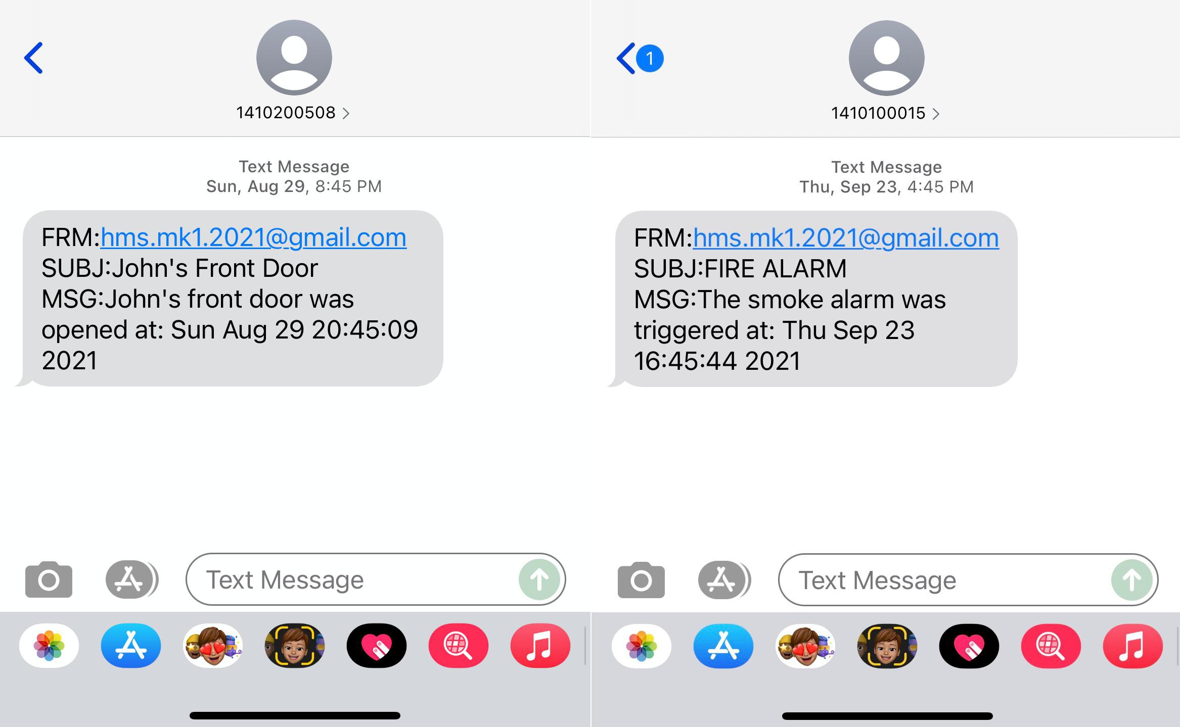
The alert system was created to send an email from the system to the user. To accomplish this, an email address was created for the project. Next, a Python library named smtplib was used to allow for the program to send emails from its email address to a recipient’s email address. It was later discovered that the ability to send an email and have it appear in the form of a text message on a cell phone is a service provided by most cell phone carriers. This capability allowed for the notifications to go directly to the user’s phone instead of email account and produced a far more effective alert system.
The program monitoring the status of the doors in the home was combined with the alert system program into a single program capable of texting the user when a door opens. This program became more complicated than initially expected. This was due to the initial design sending alerts indefinitely as long as the door remained open. To solve this issue, the program was crafted in such a way that only a single alert would be sent when the door is opened. The program would then proceed to wait until the door was closed again before being capable of sending another alert. Creating such a program was a fantastic learning moment in this project.
Getting the MQ2 smoke sensor to function with the Raspberry Pi was, yet again, more of a challenge than expected. This was due to the MQ2 sensor outputting an analog value and the Raspberry Pi only allowing digital inputs. To overcome this communication, the MQ2 was attached to an Arduino Uno which read the analog output from the MQ2. This analog value varied based on the presence or absence of smoke. Through monitoring this value without smoke being present and then watching the change after introducing smoke to the air around the sensor, the value ranges indicating the presence or absence of smoke were determined. Using this information, a program was constructed on the Arduino, which monitored the analog values from the sensor. If this value entered the range indicating the presence of smoke, the Arduino sends out a digital signal. This digital output was then fed to a level converter to make the signal safe for the Raspberry Pi to receive as an input. Now safe, the signal wire was connected to the Raspberry Pi. A program was then created on the Raspberry Pi to monitor this pin, and smoke was introduced to the sensor to verify the system was properly alerting the Raspberry Pi to the presence of fire.
The electromagnetic lock used came without a power source attached and instead had an exposed positive and negative lead where a power source could be attached. A physical switch was first connected to these exposed leads to allow for manual control of the lock. Then a power supply capable of providing the required 12VDC needed to engage the lock was connected. With the electromagnetic lock operating properly, it was then connected to a solid-state relay, which was then connected to the Raspberry Pi. A program was written to ensure that the relay would switch on and off the electromagnetic lock.
With the project now capable of detecting smoke, controlling lights, and controlling the electromagnetic lock, these capabilities were all combined into a single smoke alarm system program. This program was designed to disengage the electromagnetic lock and turn on the lights if smoke was detected. This was accomplished by giving the program control over the solid-state relays dedicated to controlling the lights and lock respectively. Although not featured in the initial proposal for the project this program was expanded to text the user’s phone in the event of a fire.
After assembling the entire system and creating all the programs required for the system to perform each of the tasks set out in the proposal. The next step was to make all the programs run automatically upon the system being powered on. The first hurdle in accomplishing this goal was getting each of the programs to run properly in the Raspberry Pi’s command line. Although each program worked properly in the environment it was written and tested in, each would fail when run from the command line. After much research, it was discovered that the issue was related to the version of Python the terminal was using to run the program. Once this hurdle was overcome, the next step was finding a way to get the Raspberry Pi to execute each of the files at startup. To accomplish this a combination of methods was used. The program which receives and stores the environmental information from the BME680 was set up to run via crontab. This was done through crontab’s ability to execute programs at predefined intervals. This ability allowed for the environmental readings to be captured and stored with short intervals between each sample in the case of the current temperature readings program, and at longer intervals in the case of the program acting as a log of the environmental status in the home over time. Getting the rest of the programs to run at startup was accomplished by editing the /etc/rc.local file on the Raspberry Pi. This file is executed as a part of the startup of the Pi. Adding the commands necessary to start each program to this file caused them to also execute when the Raspberry Pi starts up.
Small alterations were made to many of the programs at this time to ensure their functionality remained consistent, despite being in constant operation. The largest issue arising from setting each program to run at startup was that the smoke sensor required time to calibrate after receiving power in order for its output to become accurate. With the smoke detector program beginning at startup, this calibration time was no longer present. To fix this issue, multiple methodologies were attempted with the solution ultimately being the addition of a two-minute pause between startup and the time at which the program begins to run.