 Silícios Lab
Introduction
Do you know how the basic circuit of an Arduino works? Every Arduino has a minimum circuit that allows you to put the ATMEGA328p Microcontroller chip into operation. It is known as Arduino Standalone.
In this article, sponsored by PCBWay, we will develop an Arduino Standalone board.
All board files can be downloaded via this link on PCBWay's shared project community.
What will you learn in this article?
- Arduino Standalone Concept
- How to create projects on circuit boards using the Arduino CHIP
- How to Build Your First Arduino Standalone
- How the power circuit for the ATMEGA328P Microcontroller CHIP works
- Arduino board RESET circuit operation
- Circuit for transferring code to the CHIP with external USB-SERIAL converter.
The standalone circuit is widely used by those who want to learn how to transform projects made with an Arduino into a professional board, and you will learn how to do that in this article.
Next, we will show you the step-by-step process for the complete construction of the electronic board circuit.
The Arduino Standalone Board
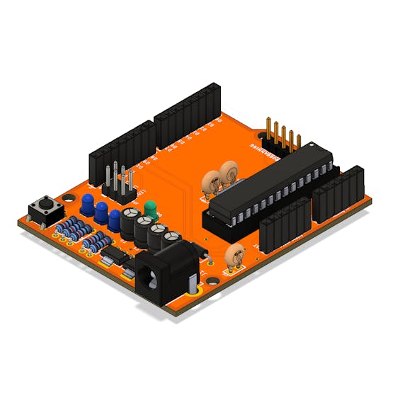
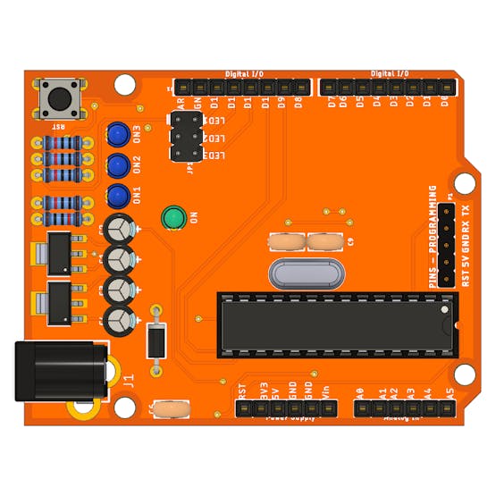
Next we have the electronic circuit of the Arduino Standalone developed. This board was developed with the same dimensions and format as an Arduino UNO.
As you can see in its structure, it has the same access connectors for digital and power pins.
We use the board area to build our own circuit according to the project needs.
See the board structure in the figure below.
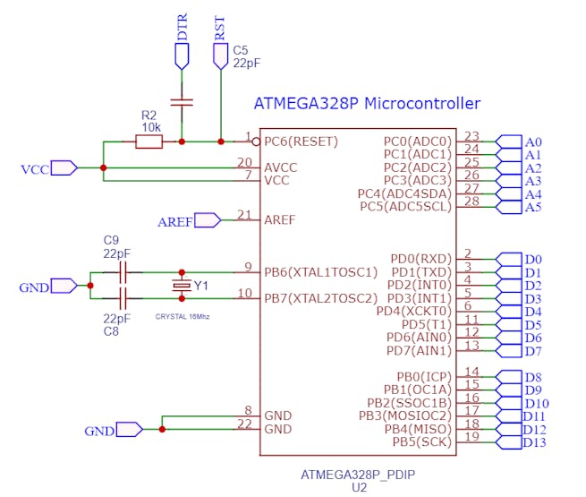
The electronic board circuit was developed from the following electronic schematic.

We will start understanding from the standalone circuit. After all, what is the standalone Arduino circuit?
Arduino Standalone Circuit
By definition, the Arduino standalone circuit is the smallest circuit that guarantees code execution on the CHIP.
This circuit is made up of 3 elements.
- Pull-Up resistor for CHIP Reset pin
- Clock circuit with 16MHz crystal and 22pF capacitors, and
- +5V power circuit.
These 3 elements form the standalone Arduino circuit and guarantee the execution of the project code.
Below is the circuit structure.
From this basic circuit we can add other electronic elements on the digital pins and develop other circuits.
For example, you can, from this circuit, insert LCD display, buttons, relays, and many other elements to the general purpose pins of the CHIP.
This allows, therefore, to create new circuits based on the basic Arduino circuit.
This is how many people develop projects with Arduino and create their own electronic boards to develop some solutions for customers.
In this project we are doing the same thing. We create our own board with the electronic components we want. In this case, we use 3 LEDs connected to the digital pins on the board.
Next, we will present the power circuit that is responsible for powering the Arduino ATMEGA328P CHIP and other components of the circuit board.
Electronic Board Power Circuit
The circuit power of the electronic board is carried out from the Jack connector on the board. See the Jack connector in the figure below.
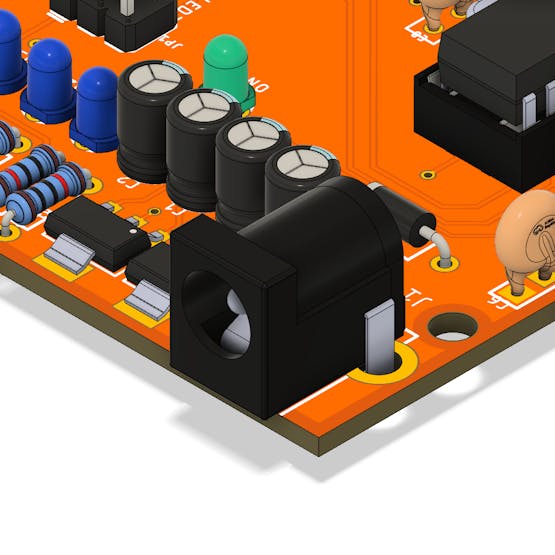
The input voltage for powering the circuit is 7V to 12V, however, we recommend using an input voltage of 7V to 9V. This prevents overheating of the CHIP's that regulate the voltage.
The circuit with the voltage regulators is shown below.
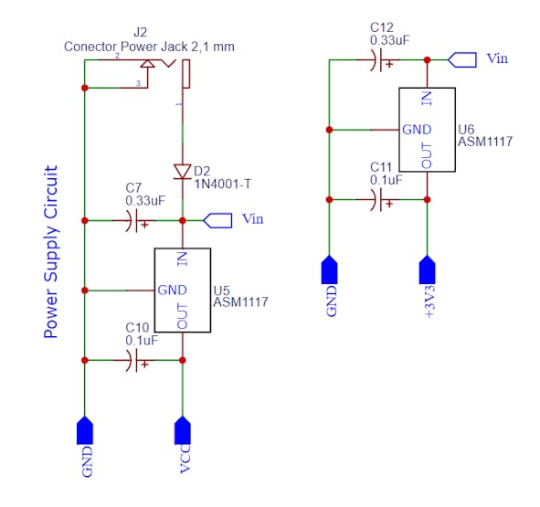
In the figure you can see the 2 AMS1117 voltage regulators and the electrolytic capacitors that form the circuit.
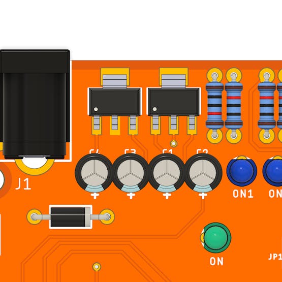
At the jack connector input we have a 1N4001 diode. This diode is used to prevent source polarity inversion and, consequently, damage the project's power circuit.
In other words, this diode ensures that the current is in one direction only. If the circuit is supplied with inverted voltage, the diode will be inversely biased and prevent the flow of current.
After the diode we have the Vin voltage entering the 2 voltage regulators. We have a voltage regulator for +5V and another for +3.3V.
The Arduino UNO has a pin that supplies a voltage of 3.3V to power some devices. We are using this same circuit to supply this voltage on our Arduino Standalone board.
The +5V voltage is used to power the ATMEGA328P CHIP and the other design elements.
To indicate that the circuit is powered, we insert an indicator LED. The LED circuit is shown in the following figure.
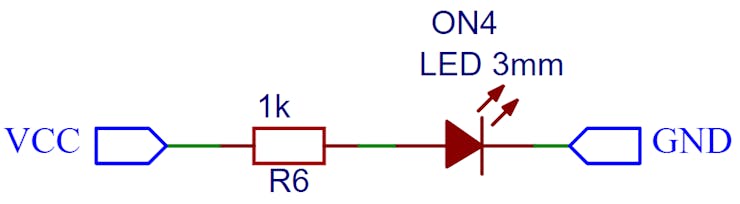
After connecting the input voltage of 7V - 9V and passing through the +5V voltage regulator, the LED will turn on and indicate that the board is powered. Below you can see the green LED on the electronic board structure.
Next, we will present the LED circuit of the project.
Developing a new project based on the Arduino Standalone circuit
You saw in the previous topics that from the standalone circuit we can add other circuits and create new solutions from the basic circuit.
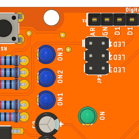
It is based on this that we inserted the 3 LED's in the project. This board was developed with the purpose of allowing anyone to assemble their Arduino and also have 3 LEDs to activate them and perform different activities.
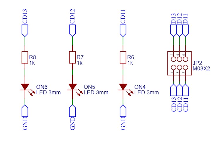
In this board we use LEDs to be activated. Each LED is connected to a different digital pin (D11, D12, and D13).
A male 2x3 header connector was used with a jumper to enable and disable the connection of the LED's with the Arduino's digital pins. This allows disabling use and connecting other loads to pins D1, D12, and D13. Below we have the LED's and the 2x3 connector presented in the Arduino Standalone board structure.
Note how important it is to understand the basic Arduino Standalone circuit. If you understand it then you will be able to create countless projects.
These LED's can be programmed based on the logic of interest to the user. For this we have inserted a connector to assist in the transfer of the code.
Circuit for Transfer of Code for the ATMEGA328P
On several Arduino boards it is possible to find a circuit with a USB connection for direct transfer of the code to the ATMEGA328p CHIP. This board does not have the circuit for this functionality.
It was not implemented because we are not interested in making the board complex and difficult to solder SMD components. Therefore, to carry out the code transfer, the user can use a USB-SERIAL converter module.
This module is shown in the figure below.
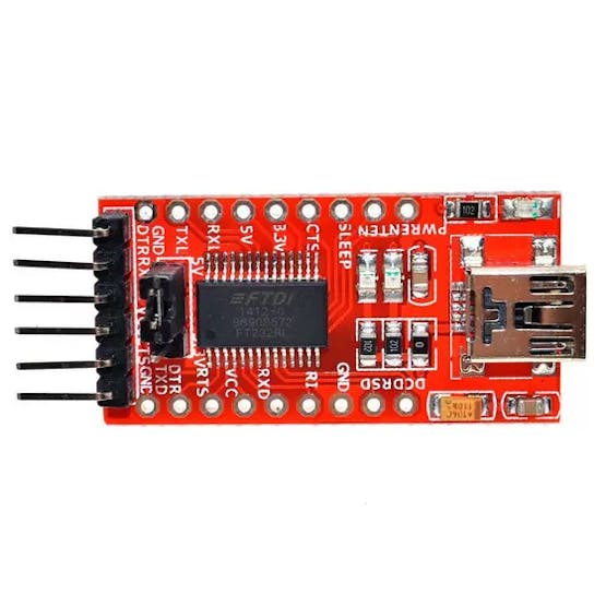
It is used to perform the functionality of the Arduino board's USB recording circuit. In short, it converts USB voltage levels to TTL standards, so the code is written to the ATMEGA328P CHIP.
The circuit below shows the connection pins between the board and the USB-SERIAL converter module.
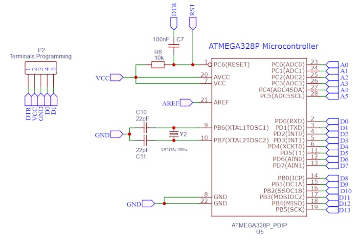
The user must connect the module to the 5 Arduino pins: DTR, VCC (+5V), GND, D0(TX), and D1(RX). These pins will be used to transfer code from the computer to the CHIP.
Also, pay close attention, it is necessary to use a 100nF capacitor (C7) on the RESET pin. If this resistor, the CHIP will not be able to receive the proper pulse on the reset pin and start the code transfer.
Finally, we have the reset circuit.
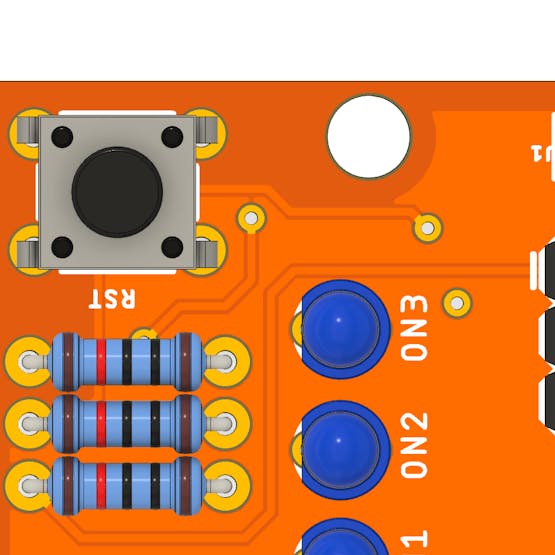
Arduino Standalone Board Reset Circuit
The reset circuit consists of a button connected to the reset pin of the ATMEGA328P CHIP. This button is used to allow the user to restart the application if any problem occurs during the execution or testing of the project.
The electronic schematic of the project is presented below.
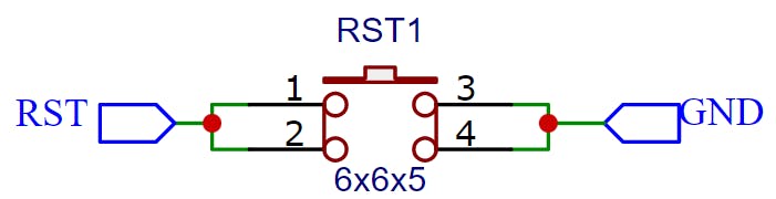
Every time the button is pressed, the chip's RESET pin receives logic level 0 and resets the code application.
This electronic board has been manufactured, assembled, tested and validated.
Below is a video showing how it works.
Conclusion and future updates
The developed board presented excellent performance and has already been used in different projects. 94% of the components used on the board are PTH. The only SMD's components are the 2 AMS1117 voltage regulators and they are very easy to be soldered manually.
This allows the board to be assembled in classroom workshops or by others interested in using it to build their own Arduino.
In future updates we will develop a new version with a USB recording circuit to facilitate the direct recording of code from the computer to the development board.
All future card updates are available soon at the end of this article.
Take advantage now and get 10 free units of this Arduino at your home. Click here and enjoy.