 cmholm
Goal: the chassis will measure 60cm x 20cm x 10cm, the left and right ends shaped as half circles. The working surface will include a chording keypad (left or right side), LCD panel (center), and touch pad (opposing side), and a shutdown button. The top edge of the device will include power switches, reset buttons, mains power plug, and peripheral ports. The bottom edge of the device will remain unblemished. The interior of the device will include power supplies for the RPi, and the LCD panel and controller board, a battery for use away from mains power, and WiFi dongle.
Rev 1: the chassis size is determined by the two salvaged LCD panels I have available, both of which are 15" displays. No battery will be included. No WiFi dongle will be included. The lumber is 1/2", cut into two pieces and bolted together. These will be routed out as needed to make room for the other components. As such, the completed device will be much heavier and more unwieldy than desired, but as a prototype, it'll do.
 Nicholas Hill
 IT-Wizard
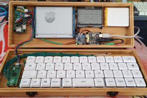
 Nick Scratch
 ct
ct